The Tide Monitor
TL/DR
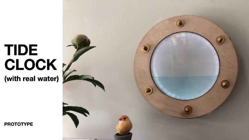
This is the video of the final result:
Your personal sea at home
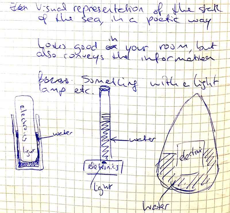
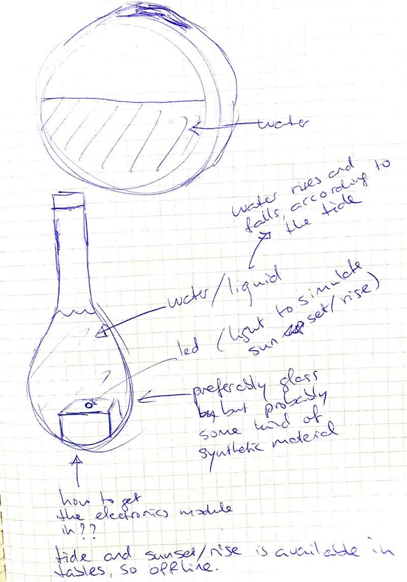
The idea is to have a nice or even poetic visual representation of the actual tide of the sea. As there are many seas and shores in the world, I choose the sea in my hometown: Noordwijk.
I want it to be something that looks good in your house, I am thinking of glass, water, light.
It shows at the minumum the current tide. If time permits I can add a sunset and sunrise (maybe with light). Both parameters are (in their basis) calculatable: tides for exmample are dependent on the position of both moon and sun. I know that there are tables of sunset/sunrise, as there are tables of the tides. That means that it could be possible to make a basic offline version by storing these tables somehow on the PCB that I will hopefully learn to create.
Even better would be a version that has access to online data, for example the actual tide. And the weather, so the device could also give an idea about waves and wind.
Who will use this?
I think the information it conveys is useful for people. For example, if you want to go for a walk or run at the beach it’s handy to know if it is ebb or flood. One glance on the Tide Monitor and you know enough. It is also of interest for surfers, especially when I can get it to collect online data.
But above all, I imagine it to be a nice object to remind people of, and to connect people with, the sea.
The plan
You can read a breakdown of my plan to make this on the Applications and Implications page
process
peristaltic pump
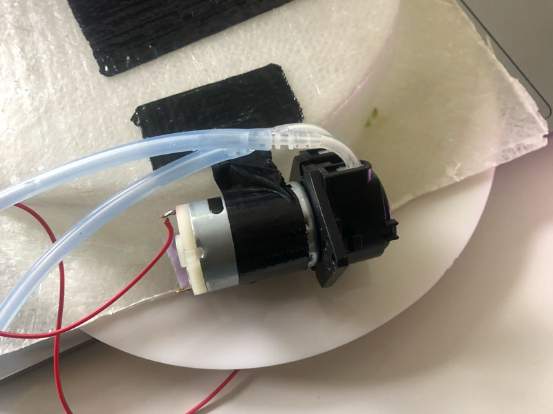
First, I look into the persistaltic pumps. I find out that they are not hard to DIY:
Basically, a peristaltic pump is a DC motor that has some extra gears on top. These create alternating compression and relaxation of a hose or tube that flows through them, drawing content in and propelling product away from the pump.
It is tempting, but since I have only four weeks left, I opt for the safe way, a prefab pump. If time permits, I will look into the DIY variants later on.
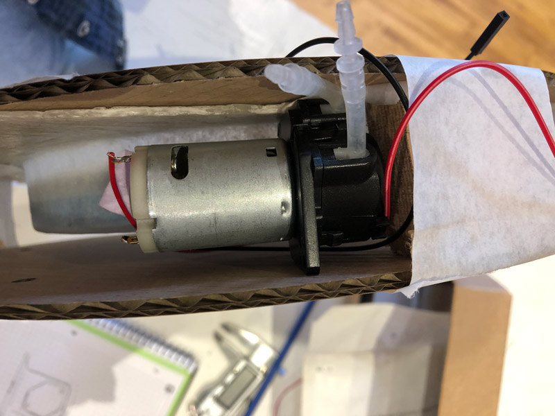
The prefab pumps are a bit bigger than expected, but I find two that look usable and are about the same size.
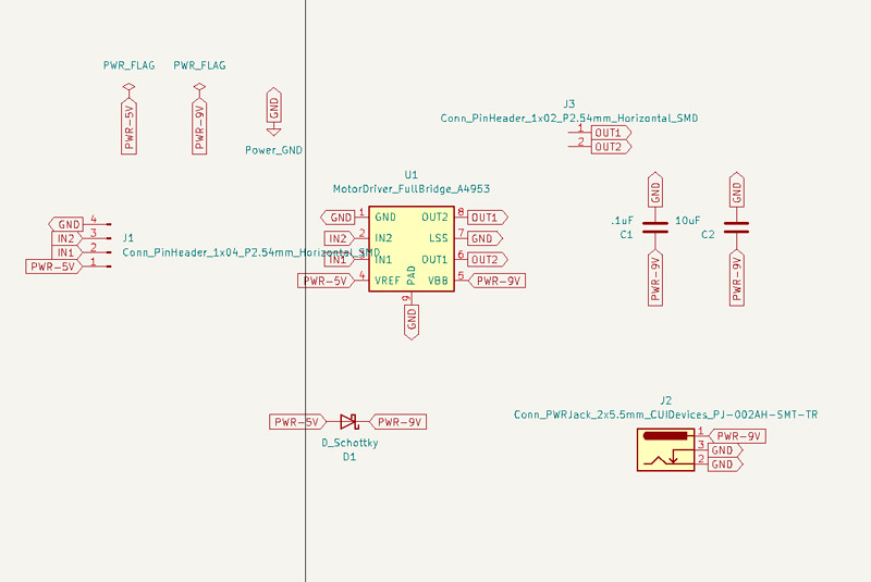
I decide to start with the 6V one and design a motor driver breakout board for it, based on the A4950 driver that I used in the Output Devices week.
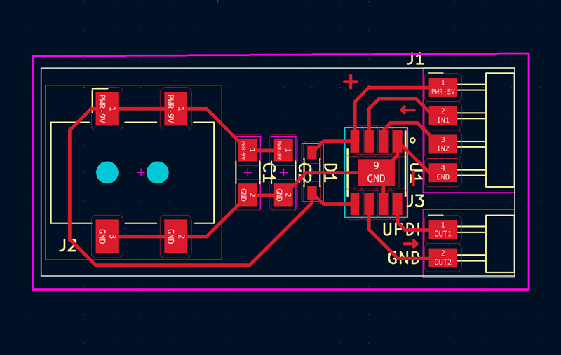
With this board I can test the pump without the need for a complete control board, as at this point I have no clear idea about it. By designing it as a breakout board and keeping it as simple as possible I can focus on its sole purpose and iron out difficulties easier. I still have my troubles from theOutput Devices week fresh in memory.
The board has 2 output pins to drive the pump, and two input pins so I can control it with an Arduino, or later with my own PCB control board. It also has a barrel jack connector for 9V or 12V input because the motor needs a bit more power than an USB port can deliver. I plan to use this connector later to chain it to the 9V/12V input of the control board, so I need only one power source.
There are also 2 capacitors, as per the advice in the datasheet. In the design you also see a diode, but I never soldered it because I always powered the controller from the 5V USB input.
testing the pump
Milling and stuffing of this board went without problems and the time came to finally test my new motor driver board. For this test I connected it to an Arduino and wrote a sketch that set one pin to HIGH and the other to low. That should be enough to get the motor spinning and the pump pumping. I connected a 9V battery to the barrel jack, as the motor was rated 6V.500mA . Alas, no spinning motor. I took out the multimeter and performed the usual checks. 5V came in from Arduino. The HIGH pin from Arduino also 5V. Into the motor driver also the correct pin on 5V. Out of the motor driver: not even 1V. I checked the 9V input on the motor driver: less than 3V. Weird. I checked the battery, a little bit above 6V. Hmmm, maybe not enough? I noticed that the input became low when I actually wanted to drive the motor, with both pins set to LOW, there was enough Volt in the driver input. I concluded that the battery was not strong enough and went on looking for an adapter. I found one with the right output, 6V / 500mA, but the jack was too small. So I cut it and soldered on a bigger one.
Below is the result of my first test. I speeded up the video 8x
In this test you can see the flow of the water, as well as the current the 6V pump takes. Almost 500mA.
This test uses a 12V pump, it uses about 150mA.
Because the 12V pump works better with my litte breakout board, and also uses less current, I decide to use it in my final project.
testing the waves
In an earlier stage, when I was still contemplating how the clock could give an impression of waves I did some tests with an old clock and a lot of hotglue:
Here I test how and if I can make waves in a round clock enclosure:
After giving it a lot of thought, I decide to leave the wave part. It provides a bit too many unknowns for the time I have left. For creating waves I will either
- have to move the whole thing (probably too heavy, also not a good solution)
- have to move at least the clock face part (clock face is detached from back, will it hold?)
- have to move something under the water inside the face (will I get leaks?)
Even without waves there are many problems still to solve. For now I will focus on creating a clock with a rising/falling water level, and some great lighting for sundown/sunset.
creating the tank
I described this process in the Wildcard Week
Important here is the decision to make the walls of the tank a bit higher, so that I could place a LED strip along the inside wall and fill it up with clear or even tinted epoxy. On top of that I use a white acryllic layer as a diffuser for the LED lights.
thinking about the invisible tank
I spent quite some time on deciding how to place the second tank. The original plan is to place a second, separate tank behind the tank that I made in the Wildcard Week. But I am worried, as I also have to find a place for the pump. And the pump is not that small, it will add about 40mm in thickness.
So first, I think of making the the second tank half the height and about twice the width of the first tank. That will save me some space to add the pump (and electronics) on top of it. See the schematic image below, in which you look at the clock from the side:
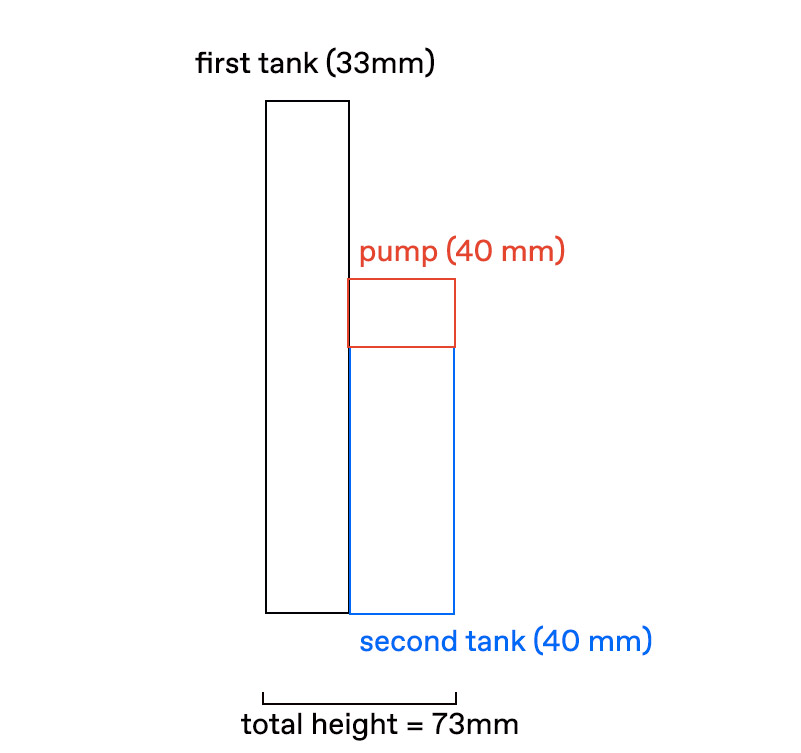
But still, that means I will end up with a total thickness of 77mm, and that us without the enclosure. After a good deal of thinking and talking with people, I finally see a better solution:
I think it could be working really well to use the white acrylic to create the second ‘invisible’ watertank. I will still use the LED lights behind it, but instead of filling the whole bottom with epoxy, I will just cast the LED lights in epoxy.
See the image below. The lowest ‘floor’ is the second tank, with LED in the sidewall. Then comes the white acrylic layer, then the first visible tank and the glass that closes it off.
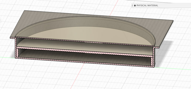
It means that the front tank will be less deep, but I calculate it will still be deep enough (about 15mm) to show a good amount of water. It also means that the back tank will hold not enough water to fill the front tank completely. But this is not a problem, as long as more that 3/4 of the front tank can be filled and that is the case.
The result will be a much less higher sidewall, namely just the height of the whole tank and maybe some extra for the front glass. I also think this solution will result in a much sturdier endpiece.
a place for the pump
And the pump? I decide to place it in the rim instead of in the back. That means that the whole enclosure will end up to be about 50mm in height to make room for the pump. Much better than the 70mm I was looking at.
When I have casted the epoxy resin clockface tank, and play around with the placement of the motor, I realise it is even much easier that I thought. The pump is designed so that you can fit it nicely in a corner, and it fits snugly behind the rim of the tank. To keep it out of sight, I just have to make the front plate a little bit bigger, but that’s no problem
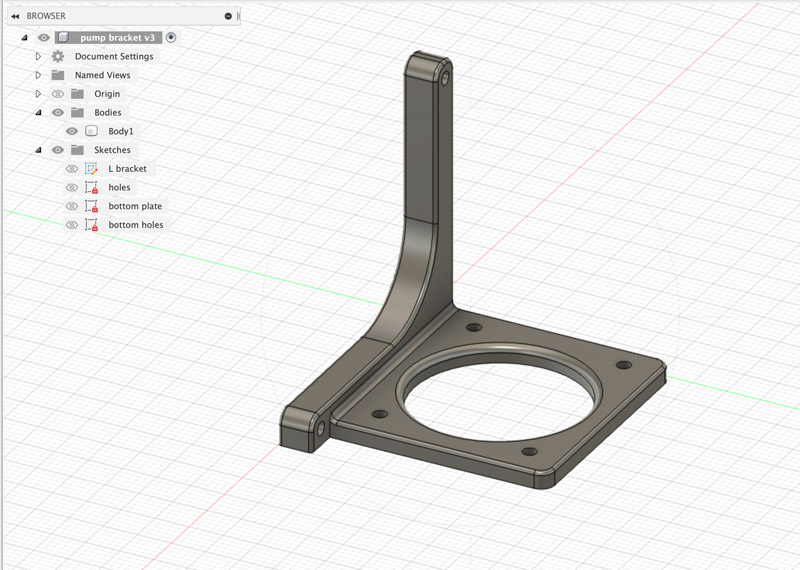
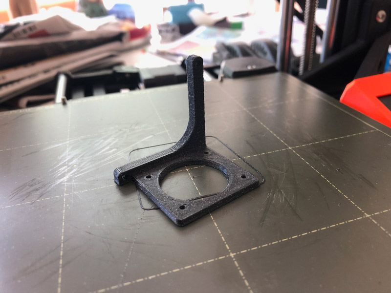
3D printing brackets
To be able to attach the pump, and also the PCB boards to the back plate, I design a couple of brackets. I am amazed by how easy this is by now. It is maybe not the greatest design, but I draw the brackets in Fusion without much trouble. I export them to .dxf and use PrusaSlicer to create gcode. I print everything on the Prusa mini+ that I have acquired by now.
water level sensors
With a plan for the second tank, it is time to tackle another problem: How do I know the level of the water in the tanks? I decide that I only have to measure the level in one tank, the invisible one, and that I can calculate the level in the visible tank from that.
To measure the level, there are 3 sensors that come to mind:
After testing the Soil Moisture sensor turned out to be useless. It does detect moisture, but not the liquid level that I need. The Water Level Sensor does what it says: it measures the level of the water on its sensorpad. Although not very precise (the level seems to decline a bit after a while) it seems good enough for my purpose. The only problem is, it only measures to 40mm max, and my tank can hold almost 5 times as much (its diameter is 200mm)
The Time of Flight sensor is a nice suprise. It works better than expected because the one I have (VL53L0X) has a bigger range (50-1200mm) than I need. And I also did not expect it to be working with clear water. But in the initial tests it does. But will it work in a tank with random LED lighting? Only one way to find out.
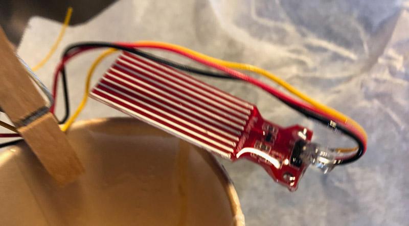
So I offer up one of my handy lunch boxes, to function as a testbed for the sensor. I tape the sensor at one end, and glue an epoxy LED at the other. I make holes in the lid for the cables and use some hotglue to make it watertight enough. I also add a plastic valve that I want to use in the clock, so I can connect the silicon tubing from the pump. Then I connect the pump.
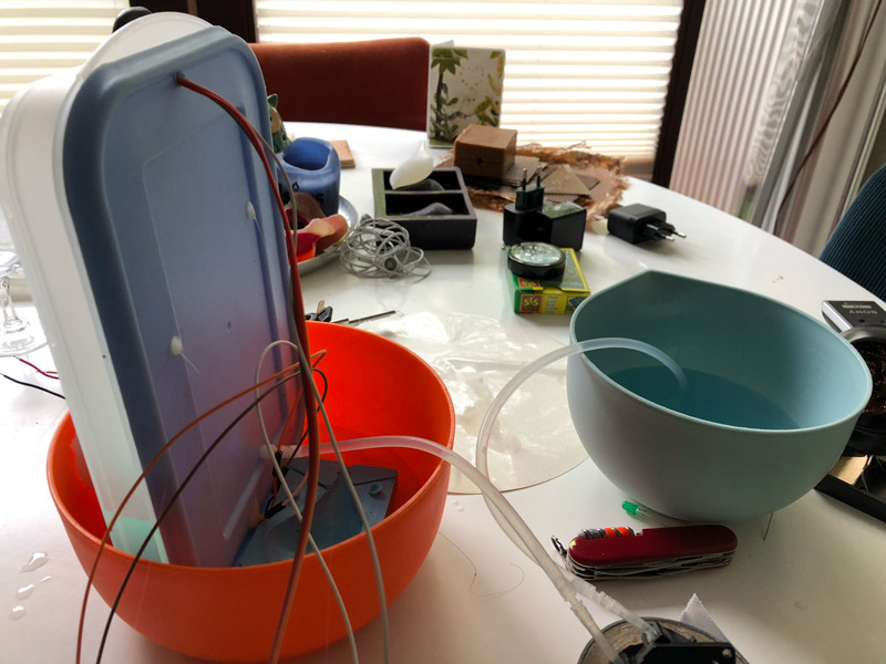
I hook everything up to an Arduino, and combine 3 different Arduino sketches (one that reads the sensor, one that flashed the LED and one that drives the pump) to one sketch to test how the sensor will react to rising/falling water levels in a LED illuminated condition.
When I start the pump I see that the sensor initially reacts pretty accurate. But when the water is about 10cm from the sensor, the readings start to flatten out. I wonder if that is because this is not the ideal range for this sensor. I have to wait until the VL6180 arrives, which as a smaller range, to test that out.
When the VL6180 arrives, I do some tests with it as well. Although better than the VL53L0X, I also get inconsistent results here. Apart from that, the VL6180 is much bigger than the VL53L0X and will not fit between the two acryllic sheets, where I have a space of 15mm left.
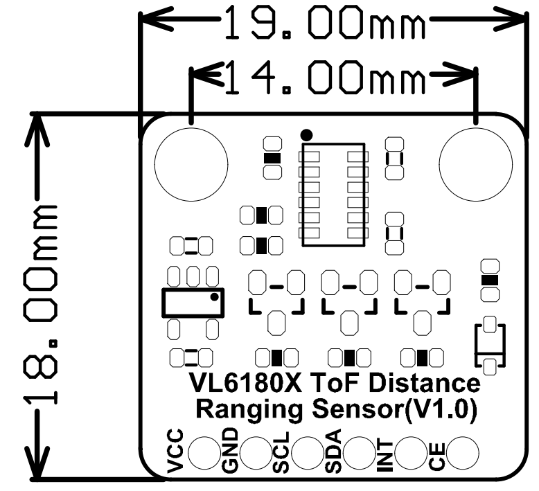
So in the end I fall back to a trusty little resistive water level sensor. It is too small to measure the water in the whole of the tank, it can measure only depths of 40mm. But I plan to place it in the middle of the invisible tank. With high tide and low tide, there will always be a moment that the level can be measured. I will use that moment to calibrate. And during the time the sensor is not functional I will fall back to measuring of the time I let the pump run. For that I will measure how much water the pump displaces when running for a certain amount of time (day 30 seconds).
Because this sensor will be submerged in water, I use epoxy to make it waterproof.
In testing I also found the following:
- keep the valve as low as possible to be able to pump all the water out
- make sure the tubes do not suck themselves vacuum against the wall of the bowl
testing the RGB led strip
I want to have to possibility to color the water with light and plan to use a LED WS2812B RGB Led strip for that. As I want to place this LED strip behind the wall of the first tank and inside the second tank, they need to be waterproofed. So I plan to cast them into epoxy when I cast the watertanks.
Before I do that, I first need to figure out how they work and how to connect them. In the inventory I find a strip that has more than enough lights.
The good thing about this LED strip is that all RGB LED’s are individually addressable, while still needing only one pin of my microcontroller. For this output I do not even need a breakout board. Just one pin from the microcontroller.
I find this tutorial really helpful in the process.
I soldered 3 wires to the respective pads on the strip, and added a dot of hotglue to keep them tight. Then I connected the strip to an Arduino UNO. I used a 330ohm resistor on the ground line. The LEDS did light up, but it seemed I could not control them. After staring at the circuit for a while, I realised the resistor needed to be on the signal line. Now I had control over the LED’s. Cool!
The LED strip I was testing was kind of small, about 14 LED’s. When I placed them in the mold I realised it would be much more interesting to have LED’s in the whole rim. Henk had plenty strips lying around, and I started testing with a 5M water resistant (not waterproof) strip. Once I got that to work the light effects were mesmerizing :-)
I decide to use a strip of 40 of this 5V WS2812B RGB LED strip in the back of my clock.
LED lights in epoxy
To test how the lights work inside the epoxy I made 5 small LED strips of 2 lights each, and soldered the 3 wires onto them. Luckily I tested them all before casting, because I had two of them connected at the wrong end.
After casting the clockface tank (read about that here) I mix some fresh epoxy and start experimenting with my makeshift pigments.
At this point I am thinking of coloring the epoxy that I use to waterproof the LED lights. So I mix epoxy with different pigments. These pigments need to be powdered or solid. Not water or oil based, because that can have nasty side effects on the ratio of the two components. The pigments I try are:
- cornstarch (for translucent white)
- blue chalk
- blue eyeshadow
I also make a tester without pigments.
Cornstarch
First I try the cornstarch, as I think a near translucent white will work really well. I have to add more than I expected. The epoxy stays transparent quite a while. When I have finally added so much that the transparency is gone, I put one of the LED strips in a cup and pour the epoxy over it.
When I check up on it after about half an hour, I see that there is a white layer on top of the epoxy resin. First I think the cornstarch is so light that it started to float to the top. But lab assistant Michelle points out that the white consists of little bubbles and she advises to use alcohol spray to get rid of them. I use a squeezy bottle with 70% ethanol, and indeed, the bubbles seem to go away. I leave the cup to cure.
Blue Chalk
After mixing in the cornstarch, I add some blue chalk that I grind to powder in a mortar. I do not need much of this, the small amount of epoxy resin that I have turns blue pretty quick. I use this batch for the next cup with a LED strip.
Eyeshadow
I follow the same process for eyeshadow. After that, I also make some combinations of starch and color.
Then I leave everything to cure for the night.
The next day, I have 5 epoxy testers with light. I test them and although I do like the effect of the one that used starch and chalk, in the end I decide that transparent epoxy and the white acryllic sheet are just fine.
Because I now need to make a LED ring instead of just pouring an epoxy bottom over my lights, I need a mold for a LED ring. But at this point, I had enough of going back and forth with the Shopbot, and to be honest, I am also a bit running out of time. So I take a shortcut. I use the epoxy tank that I already have as an outer mold. Inside it, I put the LED lights. And then I use an upside down dog waterbowl as an inner mold. It really is just the right size!
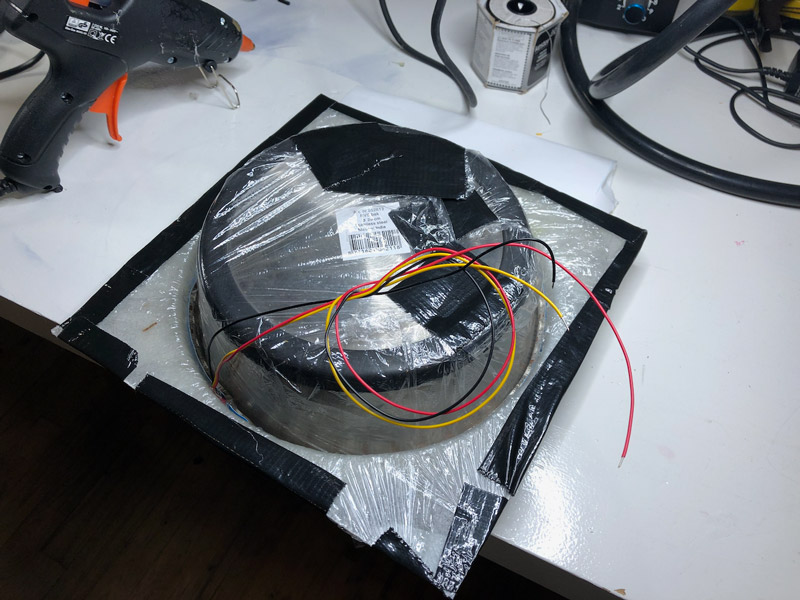
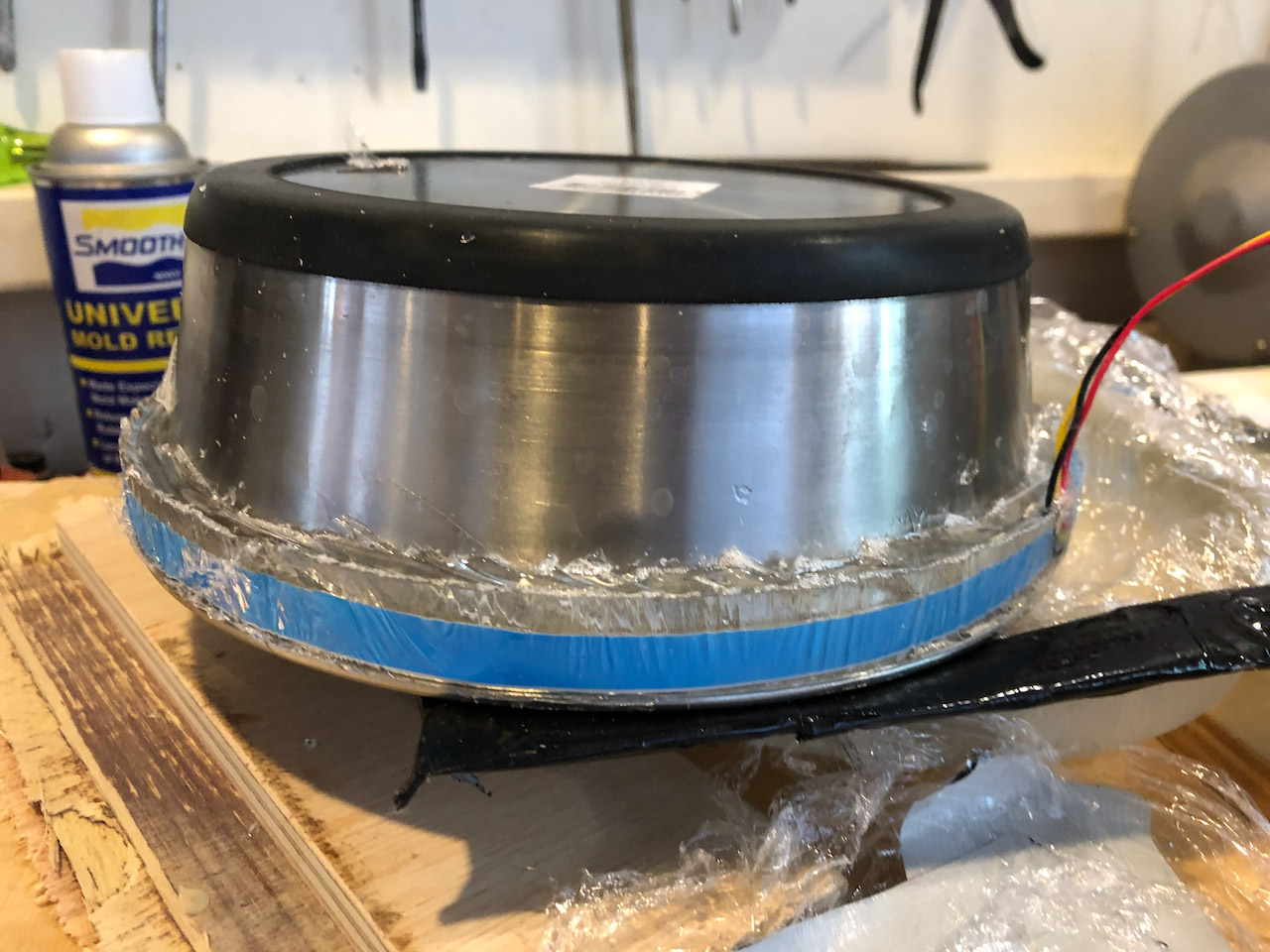
It works, but barely. I leaves me with a LED ring allright, but it has a lot of bumps and is uneven so it needs some tuning to get it flat enough to hold an acryllic sheet.
making the enclosure
I want to make the clock look like a porthole.


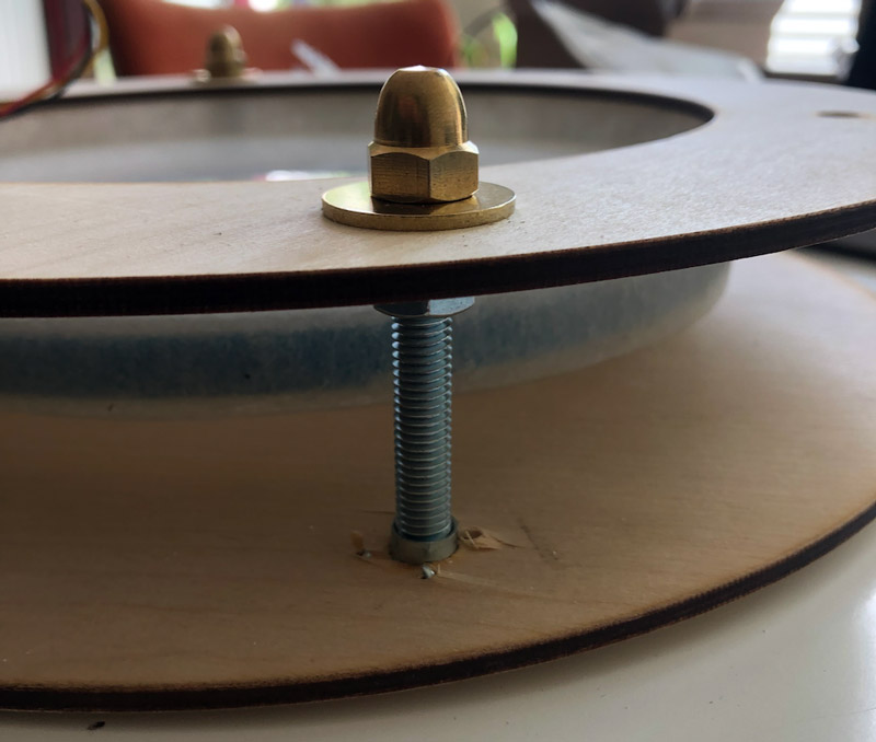
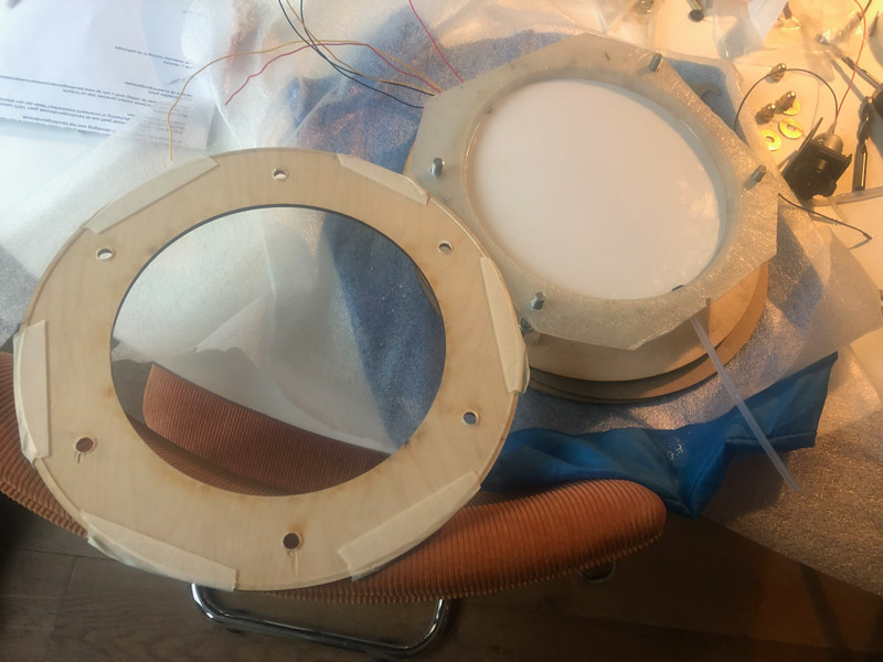
For the front and back plate I decide to use plywood, that I cut with the lasercutter. I want to use threaded rods to connect the backplate to the frontplate, leaving enough room for the tank and the motor. The capnuts are screwed on the front side and press the front plate down, see photo below:
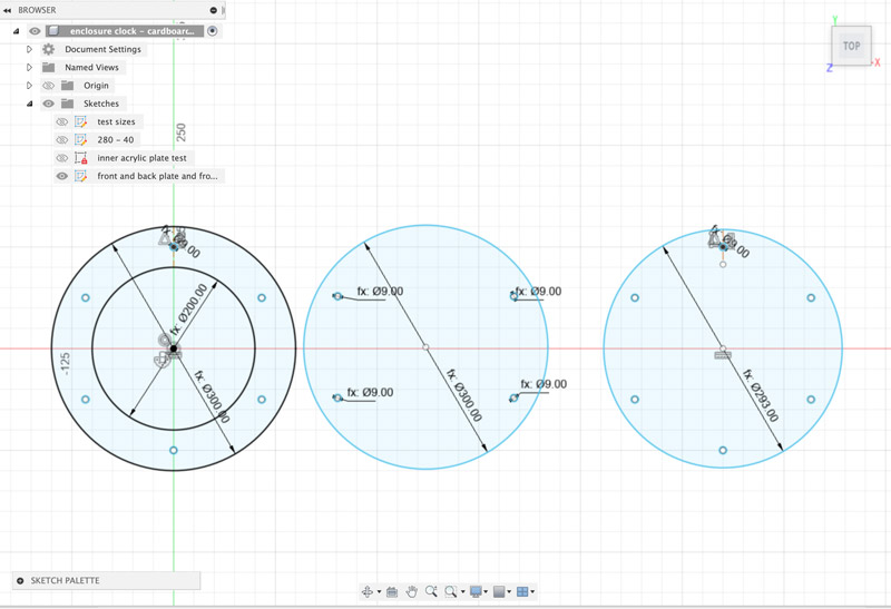
I use Fusion to make the designs for the lasercutter. I add the holes for the threaded rod in both front plate as back plate as in the clear acryllic plate that will seal the front, so that I am sure that all holes will line up. Initially I make these holes the same size as the rods I use (8mm).
I use the lasercutter and a lot of cardboard to test out sizes for rim (to hide the pump) and height (to calculate the size of the threaded rod )
When I am satisfied with the dimensions, I use the lasercutter once again, but this time with a sheet of 4.5mm plywood. And wouldn’t you know it, for the first time ever, the laser starts with the outline and not with the inside. Which means that the inner circle was cut out after the outer circle, which means there is a tiny bump that I have to sand by hand.
Also, the laser does not cut completely through, even with a very slow speed and high power. I used a very sharp nice to cut the back of the sheet, to get the circles out clean.
In assembling I realise that the holes for the rod are not big enough. I made them exactly the size of the bolts I have. Individually they fit perfectly, but in assembling even the tiniest offset would give me trouble fitting all bolts at the same time. I hand drill them to 9mm. Next time I will allow for some spacing in this case and make the holes bigger in the design.
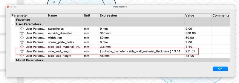
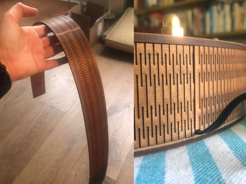
Next step is creating the sidewall. I want to use wood here as well, and that means creating a living hinge. I find a nice extension for InkScape that does all the hard work for me. All I have to do is typing in the width and height of the living hinge, and press OK.
In Fusion, I make a sketch with a rectangle that has the desired width. For length, I make a calculation in the parameters that calculates the circumference of a circle. For the diameter of this circle I use the diameter of front plate, minus the material thickness of the sidewall that I measure to be 3.5mm. This way, I reason, the cylinder that I make with this living hinge will fall nicely inside the plates.
The lasercutter gives me problems again, even though I use a speed of 50% and full power, the laser does not cut through the material in one go. Luckily, I have fixed the material pretty good, and I notice that the living hinge is not yet free without moving the whole plywood sheet. So I just restart the job, and this time the hinge comes out. But just though!
When I try it in my clock, I realise that I have not taken the thickness of the front acryllic glass in my measurements, so the height is maybe a bit too low. Also, I have an overlap of about 3mm that I do not really understand.
But this is good enough for now, and now that I know the width of the material, I can draw and lasercut the acryllic front sheet, the looking glass. I want to make it almost the same size as the front plate, but minus the width of the sidewalls, so I have something to push against the sidewalls from the backside. It meant I also have to add screwholes in this plate.
I make a design in Fusion and use the thinnest acryllic that I could find. This time lasercutting went without problems.
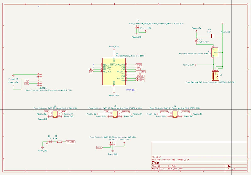
PCB Design
I already have the motor driver board, but I also need a central control board. This board needs to do the following:
- driving the LED strip
- driving the motor breakout board
- power the motor breakout board
- reading the water level sensor
- receiving data from the Wifi breakout board
- have a 12V input so that it can power the motor board
- have a 5V circuit for the microcontroller and the LED lights
- a regulator to step down 12V to 5V
- be able to be programmed (UPDI)
- be able to be debugged (FTDI)
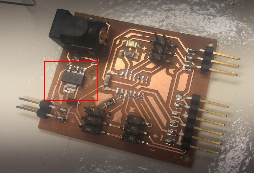
I use Adrianino as a base for my board, but change the number of connectors so I can connect more than one board. I also add a diode, to protect the regulator when the board is connected via UPDI or FTDI
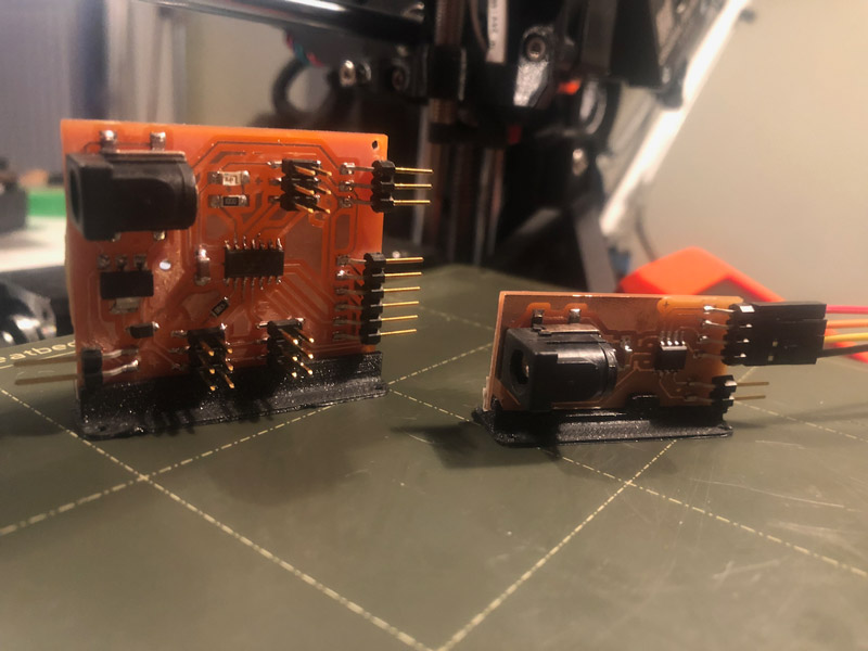
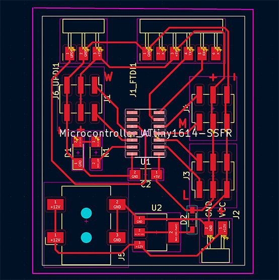
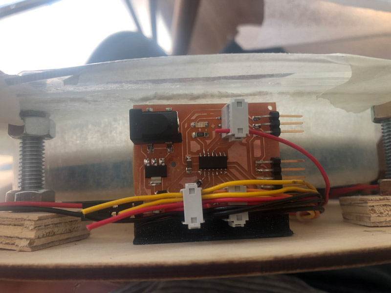
I originally planned to place the PCB in the back of the enclosure, but that means using a lot of flat headers for the connections, and the traces just will not fit. So I decide to use vertical headers (much easier!) and place the PCB’s in the rim, like the pump.
For this goal I design two little PCB stands so I can screw them to the back plate.
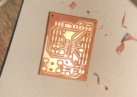
Milling of the traces goes fine, but when I want to load the holes and outline in Mods, the computer is not responsive anymore. I have to reboot it. I am very lucky to have remembers the X home location. And Jonathan, who milled before me, remembers his Y home location. So I have the coordinates to start the job again after rebooting.
After milling completed (this took one hour in total, including rebooting the computer) I see that at the bottom right corner of my board the traces are not cut completely. I am able to fix this with a knife.
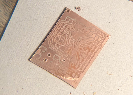
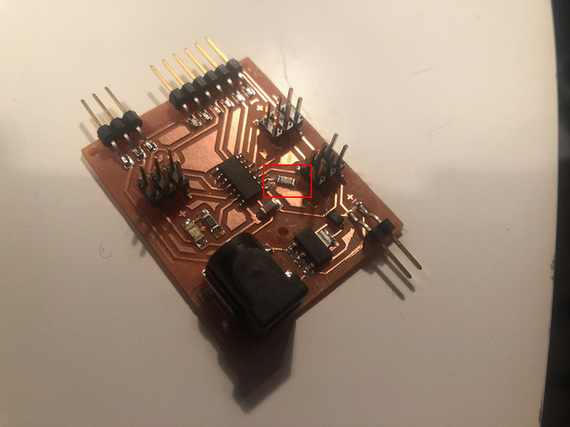
Stuffing went without problems
testing the main PCB
When I try to upload a blink test sketch I get an error:
avrdude: stk500_getsync() attempt 1 of 10: not in sync: resp=0x30
Oh yeah, I forgot to select the Board type in Arduino, it is still set to Arduino UNO. After correcting this I get:
UPDI initialisation failed
Just to be sure, I take out the soldering iron again and tip all the pins of the microcontroller again. Then I test the board again, and to my relief I see the words “Pinging device…”
And then the LED starts to blink. One down, the base is functional.
Next test is the 12V connection via the barrel jack. I have an adapter with an output of 12V / 500mA, because this is what I need (and have tested) for the peristaltic pump. I have a regulator on the board to step down the 12V to 5V for the microcontroller. But I realise I have not checked the max current of the regulator. I check the datasheet of the AtTiny 1614 and in the section about Electrical Characteristics, Absolute Maximum Ratings I find the maximum input on the VDD pin: 200 mA. Does this mean that I have to step down the current from 500mA to 200mA? No, because it turns out, 200mA is what the controller draws and should be supplied by the adapter. It is not the other way around.
I also realise I have forgotten to add a 330K resistor for the LED strip signal line. It looks like I can add that still to the board, by cutting one of the traces and adding a resistor to connect them again.
 fixed it, added a 470k resistor for the LED line
To test what current the board actually uses, I decide to connect it to a lab power supply. But before I can do that, I have to solve one extra problem: the fact that I have used male connectors on my board, but also have ‘male connectors’ (stripped wires) on the peripherals. Henk gives me 6pin IDC female connectors and leaves it up to me to figure out what wire connects to what pin. I use this page to figure that out.
First, I want to test the LED ring. I copy the code that I had working for Arduino, but ofcourse that does not work for an AtTiny. And so I check former FabAcademy students. I find a reference to Spence Konde’s tinyNeoPixel library, that sounds like a great solution to my problem.
But the LED rings do not light up. After some testing I find out that the output of the voltage regulator (LM2940IMP) is not 5V but a mere 1.5V. I can see this also in the onboard LED, that does not shine as bright as when testing from the FTDI. I have no idea why this regulator has such low output and online I can not find any reason either. I decide to swap it for another one I have (NCP1117) and with that one the onboard LED shines bright as ever. The multimeter confirms that its output is 5V. An then it works! One by one, the LED lights light up. 40 lights draw about 300mA, althoug it seems that after a while, the board resets itself after lighting up about 20 lights. I decide to leave that matter for later, and to focus on testing the sensor first.
I should have investigated this further, as later, I ran into problems here. Turns out the NCP1117 had a short. In investigating the matter, I also found why the LM2940IMP was not working. Although they have the same size and pins, the LM2940IMP has the ground on the middle pin, where the NCP1117 has the voltage on the middle pin. In my KiCad diagram I used the footprint of the NCP1117, and so that is the one that will work with my PCB.
I get the sensor to work without too much trouble. Only thing is, I forgot to connect it to an output pin of the microcontroller instead of the 5V line directly. This is better, because when it is constantly powered it will corrode because of the moist it comes into contact with. For now, I use one of the pins that I planned to use with the Wifi board for that purpose. The Wifi board is great to have working, but for a demo of my clock not stricktly neccessary. And I might still be able to use it with the FTDI connector when I really need to.
After creating proper wires and connecting the motor, that also works. A big relief!
Assembling
When I have all the parts ready, I start to assemble.
First I use a dremel to flatten the LED ring. Also use a file to finetune. This is more work than expected. When creating this LED ring I wanted to take a shortcut by using an upside down dogbowl as a mold. Although that meant I could cast without spending too much time, this also means that I have to invest a lot of time after casting to tune everything up. Next time I will take more care and time in the beginning so that I create something that actually fits. It will maybe not save time, but will result in better quality.
When the ring is flat enough, I push it in the glassfiber container. I also add the water level sensor that I have made water resistant with epoxy. I drill a hole in the container (that takes some courage, as it means breaking the water tightness ) and push a rubber plug in it. In the plug I create little holes and draw the wires from both the sensor and the LED ring trough it. Then I apply silicone kit at the inside of the rubber plug and on the back of the sensor. I stick the sensor to the back of the container, and make sure that I measure how far it is from the bottom. Then I apply a nice layer of silicone kit on top of the LED ring and press the acrylic plate that will seal the back container on top of it. I use some weights to push the acryllic plate down, and let it rest for the day.
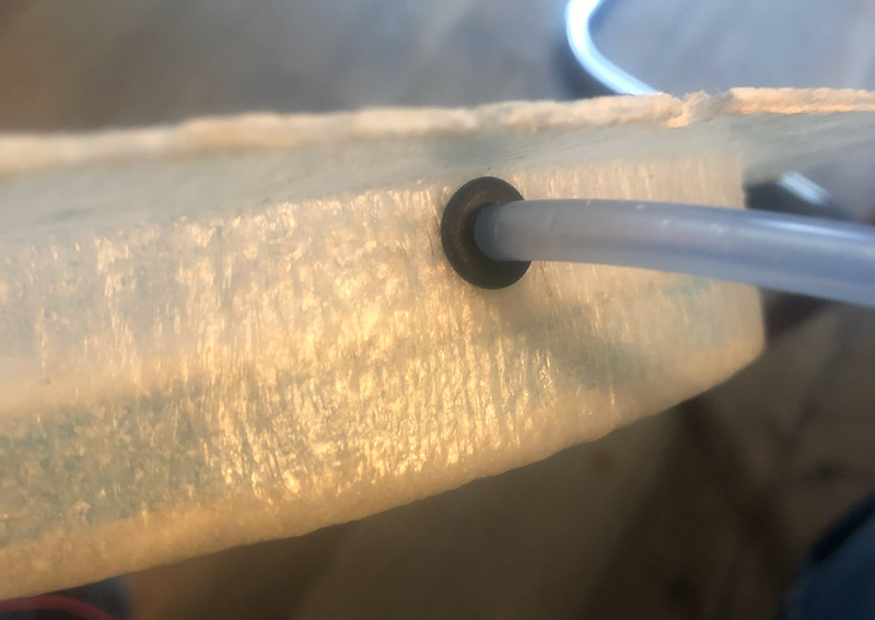
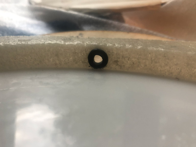
The next day, I use the silicone kit to seal off the gaps between the white acryllic plate and the wall of the container. And then it is time to add the front (clear) acryllic plate that functions as the looking glass. But first, I drill a 7mm hole in the wall of the container. This is where the tube from the pump will enter the front container. I make sure it is at the lowest position possible, so that I can pump out all the water in this container. I add a rubber ring for a waterproof connection with the tube. I do the same with the tube connection for container in the back. This is a little bit harder, because this container is already closed. I would have been a bit easier when I made this hole before adding the white acryllic plate.
The side of the clear acryllic plate will function as a ‘stop’ to press the wooden living hinge to. So I have to make sure it will be in the exact middle of the wooden front plate. So I use some tape to place it in the middle of the wooden front plate.
Then I take the silicone kit, apply it generously on top of the container and press the clear acryllic plate with the attached front plate on the screws. I press down as much as possible and use the screws and bolts to press container and clear acryllic plate together. Then I leave them for the night.
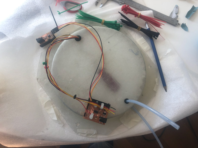
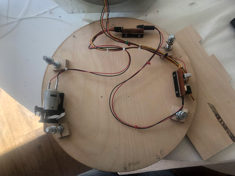
I have 3D printed brackets for the pump and the 2 PCB’s and find a good place to screw them to the backplate. I make sure all parts are well above the 2 valves, so that any leakage will not lead to shorts. Then I pay some special attention to the wiring. I group wires together, and lead them via the space between the container and the backplate to their destination.
I connect all elements, and then it is time to put it all to the real test. I am a bit nervous for this. So I take a power strip with a button to make sure I can turn of power quickly. I take a 12V 500mA adapter that I have already tested and connect it. But nothing happens. The regulator does not even get hot. Is the adapter broken? I check with the multimeter, and this seems to be the case. Weird, I thought I have seen it working.
So I take a second adapter that I have lying around. This one is 12V 1.5A. I think this is not a problem, but it is. When I turn on the power strip the microcontroller fries immediately. Ofcourse. 1A should have been the max. A lesson learned the hard way, and on a most inconvenient time. Nothing left to do that document it, replace the microcontroller and hope that that will be all.
When I discuss this with Henk he tells me that I made no mistake with the adapter. I should be able to use one that serves a current of 1.5A. So there must be something else.
My first action is to replace the microcontroller. This is much easier that I feared and takes only 10 minutes. But when I test the board again, I fry the regulator. What?
Fellow student Ben takes a look, and thinks that maybe the regulator makes a short with a trace that is pretty close to it. So before I replace the regulator, I cut of some copper to make sure it has a bit more space.

After replacing the regulator, and realising that this maybe would not have happened if I had investigated the problem in the beginning, I still had a non functional board. After some testing, I found that in burning the regulator the microcontroller also got fried again. So I replaced that one as well.
And then it finally worked. The LED came up. It was the first time I was powering them from the adapter and the regulator got hot pretty quickly. I now know this is because stepping down from 12V to 5V for 40 LED lights is A LOT for a regulator. So I tone down the LED lights to a very low brightness and hope that that will be enough.
Next test was the motor. But it did not want to work with my board. Which was weird, as I already tested that without problems. It did work directly with the power supply, so it was not a problem of the motor. So I checked the traces with the multimeter. 12V came in via the barrel jack, as expected. 5V came in via the other side, also good. But then I found that the 12V did not end up at the Vin of the A4950 controller. Upon close inspection I saw what was wrong: a misplaced trace. Probably happened during transport or assembling. It was easy to fix though, with a little bit of solder. Henk helped me here, as I was kind of mentally worn out by this time :-)
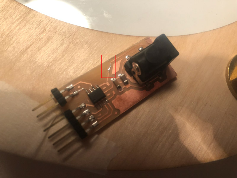 fixed trace
Coding
Because I have royally run out of time, for now I opt for a demo of the capacity of the clock instead of a realtime simulation. I decide I want this demo to run for 6 minutes, with the following sequence:
| action | |
|---|---|
| 15 seconds later | pump turns on left, high tide begins |
| 150 seconds later | pump turns off, pause |
| 30 seconds later | pump turns on right, low tide begins |
| 150 seconds later | pump turns off, pause |
| 15 seconds later | pump turns on left, high tide begins |
This will result in a 15 second pause before the pump starts, to give the LED lights time to come up properly. Then the pump runs for 150 seconds to fill up the front tank. Then the pump pauses for 30 seconds. Then it will run in reverse, so the front tank gets emptied again. Then a 15 second pause and then the sequence starts again with the 15 second pause at the beginning. So there is always a 30 second pause between the pump runs.
In the meantime, the lights will fade from a very dim bluegreen to orange in these six minutes. And back to bluegreen in the following 6 minutes. So it is kind of a sped up day from dusk to dawn, during which there will be two times low tide and two times high tide. Not accurate, but great for demo purposes. I turn up the brightness of the LED lights when they start to become orange, because light in the red spectrum needs a bit more power to be visible.
For the timers, I use the MillisDelay library that makes it very simple to use non-blocking delay timers in Arduino.
|
|
Because I am not great with color theory I hardcode the rgb values that make up the fade from greenblue to orange. For this I write a little javascript that makes use of Chroma.js . This is a great library for all kinds of color conversions and color scales.
The pump runs full speed, I use digitalWrite() to control it. To save on LED current a little bit I turn them on and of after 500ms.
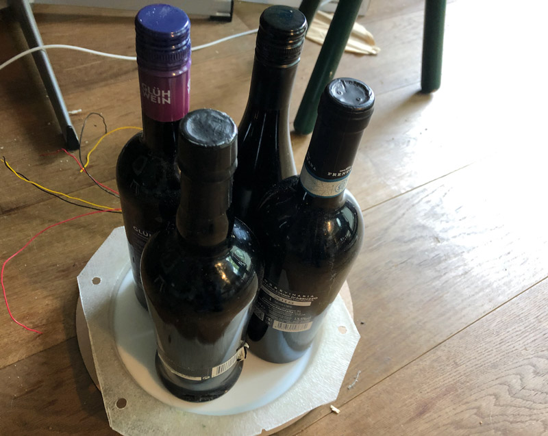
Filling up the tanks
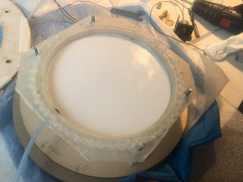
With everything connected and working, I can finally fill the tanks with water. I use the pump for this, with one tube disconnected from the tanks and into a glass of water. The back tank fills up nicely, no leaks. When it as about half filled, I connect the other tube again and start to pump the water from the tank in the back to the visible tank in the front. That also works great. It looks nice, with the LED backglow. I start to make photo’s and a video for my documentation. And then I feel water dripping. I turn of the electricity to the clock and start investigating. It looks like the silicone kit between acryllic and epoxy has come loose. I pry a bit, and without much trouble the while acryllic front sheet comes of.
I did some testing in the past weeks, because I was worried that epoxy and silicone were not a good match. But this turned out not to be a problem. I did not test with acryllic though, never thought that would be a problem. But some googling confirms it: silicone kit does not stick to acryllic,
I clean the tank as much as possible from the silicone kit. And I take the glass that I had planned to use it the beginning. I never used it, because I thought it would be a bit to small after to attach to the tank after all. But small glass probably is better that big acryllic in this case, and so I take out the silicone kit and use it to attach the glass to the tank.
I put the acryllic sheet and the wooden front plate on top of it, fasten the six bolts and prepare to leave it for the night. In that process I somehow pull on the wires that I have attached to the UPDI connector on the main control board. I hear a little snap, and to my horror see that the UPDI connector has come off. Or almost come off. It is still connected to the traces, but appearantly the traces came of. They look still connected though, so I take to glue gun and hot glue the UPDI connector back on the board. Then I test if I can still program the board. To my big relief I can.
After waiting for a good 10 hours for the silicone kit to dry, I can finally test the clock again. And it is about time, because to my embarrassment I have to admit that by now, I have only four hours before the final presentation. I already made my making of movie, but I really want a shot of a working clock. And working in this case means that the LED lights work and the pump pumps.
So I fill up the tanks. Connect all the wires. And start pumping the water from the back tank to the front tank. I see the water rising. I check the tubes and valves. Not a drop! I check the glass. Completely dry. And it stays dry. This clock finally is very, very watertight! I am so happy I shout out “It works! It works!” several times. And then I shoot some video’s of a working clock and finish the presentation just in time.
The next week, during presentations in the Waag, it is the first time that I run the clock without a computer. I just plug in the adapter. I am still a bit worried. The regulator gets so hot, will it burn again? So I wait until I have to present to turn it on. All goes well. After the presentation I leave it on, and I am proud to say, my clock ran for hours, without overheating problems. And so once again, I can say, with relief and also pride, it works!
This is my final video:
And this is the slide that goes with it:
Looking back
what tasks have been completed, and what tasks remain?
The basic principe, the prototype, works.
- I am able to pump water between the tanks.
- The clock is watertight.
- It can run independently on an adapter.
- It has LED back lighting.
But ofcourse, there is still a lot to be done:
- Although a sensor is present, I have not yet tested its workings. It is not used at the moment
- The LED lights can be tuned much better. The animation for sunrise and sunset are far from finished
- There is no live connection, so no real time data
- There is not even a realtime simulation of tides at present
There are also some things that I would do differently, knowing what I know now:
- bigger 12V traces on the PCB
- connect the sensor to a pin on the controller instead of continuous 5V to enhance lifespan
- make a better 12V connector for the motor
Regarding the regulator issues, the easiest solution will be to use either:
5V pump with 5V LED lights
or
12V pump with 12V LED lights
because mixing them puts a lot of load on the regulator.
Other possibilities to fix this are:
- using a through hole regulator with heatsink
- spreading the load accross 2 regulators: one from 12V to 9V and one from 9V to 5V
- having the LED lights dimmed (as I do at the moment)
what have you learned?
I have learned so much that I lost count. This whole documentation site is a reflection of what I learned. But in this particular project, I learned a lot about regulators and current. I also learned to reserve twice as much time for everything. I have learned that my intuition is pretty good, as there had been a little voice in the back of my head that warned me about my PCB main control board even when everything looked right. But I also have learned that I am able to materialise an idea, a vision that I have inside my head. Because the Tide Clock came out exactly as I wanted. I am really happy with that.
a word about planning
I you read this documentation closely, you will see that I only got a working prototype about 4 hours before the final presentation. Depending on where you are coming from, this means that I am either very efficient in planning, or not good in planning at all.
I found this project was hard to plan, mostly because of my inexperience with most of the tools and processes. I had no idea how much time it would take to create the epoxy container. I reserved about a day and a half for it, but it took me almost 4 days. Based on my earlier experiences in 3D design in Fusion I thought that designing a PCB bracket would take much longer than the 1.5 hour that it actually took, including printing it on my 3D printer. It took me a day to design the main PCB board, but I thought I would do that in half that time.
I only really started ‘prduction’ about two weeks before the end presentation. By then, I felt I had gathered enough knowledge to make all the final decisions that where neccessary (which pump, where does the container go, what electronics do I need).
Below is a breakdown of the global planning I made at that point. The container was already finished during the Wildcard week.
| date | planning |
|---|---|
| tuesday 31/5 | figure out how to make everything watertight create LED ring: - mold for LED ring - solder LED wire - cast LED ring |
| wednesday 01/06 | select waterlevel sensor mount led ring - drill holes for valves in container - cut container to size - drill holes for thread end in container - glue white acryl sheet into container - mount pump |
| thursday 02/06 | PCB design main board: - inputs: water level sensor - outputs: motor (9V) via breakout board, LED (5V) - wifi - regulator to step down 9V to 5V |
| friday 03/06 | milling & stuffing and testing PCB board lasercut final wooden front and back plates |
| weekend | print 3D pump bracket |
| monday 06/06 | final assembling of all elements |
| tuesday 07/06 | programming |
| wednesday 08/06 | programming |
| thursday 09/06 | documentation and video |
| friday 10/06 | final presentation |
I spent a lot of time on deciding on the waterlevel sensor that in the end product is not even functional right now. I dropped the Wifi controller pretty quickly, as the PCB design of the main board went much slower than expected.
In reality, most of the assembling took place in the last week. Wednesday, to be precise, was the day I finally assembled the front/back plates, the pump, the valves, the screws and the thread ends. On thursday, I started to assemble the electronics. I hoped to finish that, and the programming that same day, so I had friday morning for creating the video. And that was the moment it all ran out of hand.
Although I had tested everything before already with a Lab Power Supply, I had never tested it with ’normal’ current. Turned out I had some shorts that blew up the microcontroller and also the regulator. Debugging and fixing took all of thursday, leaving thursday evening for programming. And adding actual water around midnight. Exposing the giant leak that was caused by using slicone caulk on acryllic sheet. Guess who was glueing a glass plate (that I was very lucky to have lying around) with silicone around 1AM in the morning. So friday morning was spent making the video and testing the final prototype.
I finished just in time, with a crappy video, but a perfectly working Tide Clock. I redid the video in the next week. All in all, I would say that an extra three days would have given a better working experience and a good video right away.
For the water level sensor and the real time data to work, I would probably have needed an extra 7 to 10 days.
Bill Of Materials
You can view the BOM here
Sources
You can view the sources here
first sketches