Network and communications
design, build, and connect wired or wireless node(s) with network or bus addresses
Group assignment:
Group Assignment
This assignment was made with the help of ChatGPT and edited by me.
For this assignment I want to use the I2C communication protocol. It is designed to be a simple
and efficient method for inter-chip communication, particularly between integrated circuits on
the same circuit board or within a close proximity. It allows multiple devices to be connected
to a common bus, enabling them to exchange data and control signals.
I2C Communication Protocol
Overview
I2C (Inter-Integrated Circuit) is a widely used bus interface connection protocol for short-distance serial communication. It was originally developed by Philips Semiconductor in 1982. The protocol utilizes two bi-directional open-drain lines, namely Serial Data (SDA) and Serial Clock (SCL), which are pulled high with resistors.
Modes and Data Transfer
I2C operates in two modes: Master mode and Slave mode. In Master mode, the master device initiates communication and controls the data transfer. Slave devices, on the other hand, respond to the commands and data received from the master. Each data bit transmitted on the SDA line is synchronized by clock pulses on the SCL line.
Start and Stop Conditions
According to the I2C protocol, data on the SDA line can only change when the SCL line is low. To ensure a high level on the lines, pull-up resistors are required. The data is transmitted in packets consisting of 9 bits, including a Start bit, 8 bits for Slave Address, and an Acknowledge (ACK) bit.
Addressing and Packet Format
Addressing is performed by the master, which sends the address of the desired slave device. The addressed slave compares its own address with the received address and responds with an ACK if it matches. The communication is carried out in the form of packets, with the data transmitted over the SDA line and the 9th bit reserved for ACK/NACK.
Features and Advantages
I2C features include half-duplex communication, synchronous communication in the form of frames or blocks, support for multi-master configurations, clock stretching for synchronization, and arbitration to handle multi-master bus systems. It is a cost-efficient protocol with improved error handling capabilities due to the use of ACK/NACK.
Advantages
- Can be configured in multi-master mode
- Reduced complexity with only two bi-directional lines
- Cost-effective
Limitations
- Slower speed compared to other protocols
- Half-duplex communication is used
Comparison with other communication protocols:
| Protocol | Pros | Cons |
|---|---|---|
| SPI (Serial Peripheral Interface) |
|
|
| UART (Universal Asynchronous Receiver-Transmitter) |
|
|
| CAN (Controller Area Network) |
|
|
| USB (Universal Serial Bus) |
|
|
| Ethernet |
|
|
I chose to implement the I2C (Inter-Integrated Circuit) protocol for this project due to its simplicity and ease of implementation. With its straightforward bus interface connection and minimal wiring requirements, I2C allows for quick and hassle-free integration of the master and slave devices. The use of only two bi-directional lines, SDA (Serial Data) and SCL (Serial Clock), simplifies the hardware setup and reduces the complexity of the communication system. Additionally, the availability of libraries and well-documented resources for I2C programming further facilitates the development process.
For this assignment, I want to set up an Arduino Nano as the I2C master and two XIAO SAMD21's as the I2C slaves. This way, the Arduino Nano can request data from each of the slave devices.Step 1: Hardware Connection
Components:
- Arduino Nano
- 2x XIAO SAMD21
- Jumper wires
- Breadboard
- USB-C cable
- USB mini cable
Connection:
- Connect the 3.3V pin of the Arduino Nano to the 3.3V pins of both the XIAO ESP32 and XIAO SAMD21. (Power them)
- Connect the GND pin of the Arduino Nano to the GND pins of both XIAO SAMD21s.
- Connect the A4 pin (SDA) of the Arduino Nano to the SDA pins of both XIAO SAMD21s.
- Connect the A5 pin (SCL) of the Arduino Nano to the SCL pins of both XIAO SAMD21s.
First XIAO SAMD21 Code:
#include

	#define SLAVE_ADDRESS 0x31

	void setup() {
		Wire.begin(SLAVE_ADDRESS); // Join I2C bus as a slave with address 0x31
		Wire.onRequest(requestEvent); // Attach event handler
	}

	void loop() {
		delay(100);
	}

	void requestEvent() {
		char *data = "SAMD21_1";
		Wire.write(data); // Respond with "SAMD21_1"
	}
This code demonstrates an Arduino sketch that sets up an Arduino board as an I2C slave device and responds to requests from the I2C master. Let's go through it step by step:
#include <Wire.h>: This line includes the Wire library, which provides functions for I2C communication.#define SLAVE_ADDRESS 0x31: This line defines a constant valueSLAVE_ADDRESSwith the hexadecimal value0x31. It represents the I2C address of the Arduino board acting as the slave device.void setup(): This function is called once during the setup phase of the Arduino. It is used to initialize and configure the board.Wire.begin(SLAVE_ADDRESS): This line initializes the Wire library and joins the I2C bus as a slave device with the specifiedSLAVE_ADDRESS.Wire.onRequest(requestEvent): This line attaches an event handler functionrequestEventto the Wire library. TherequestEventfunction will be automatically called whenever the I2C master requests data from the slave device.void requestEvent(): This function is the event handler that is called when the I2C master requests data from the slave device.char *data = "SAMD21_1": This line declares a character pointer variabledataand assigns it the address of the string "SAMD21_1". This string will be sent as a response to the I2C master's request.Wire.write(data): This line uses the Wire library to send thedatastring as a response to the I2C master's request. TheWire.write()function is responsible for transmitting the data over the I2C bus.
#include

	#define SLAVE_ADDRESS 0x32

	void setup() {
		Wire.begin(SLAVE_ADDRESS); // Join I2C bus as a slave with address 0x32
		Wire.onRequest(requestEvent); // Attach event handler
	}

	void loop() {
		delay(100);
	}

	void requestEvent() {
		char *data = "SAMD21_2";
		Wire.write(data); // Respond with "SAMD21_2"
	}
This code does essentially the same as the first one, but it defines another address for the slave device and makes it send a different response to the I2C's master request indicating it's the second Slave.
Step 3: Coding the Arduino Nano (Master)
#include

	void setup() {
		Wire.begin(); // Join I2C bus as master
		Serial.begin(9600); // Start serial communication at 9600 baud
	}

	void loop() {
		Wire.requestFrom(0x31, 8); // Request 8 bytes from the slave with address 0x31
		while(Wire.available()) {
		char c = Wire.read();
		Serial.print(c);
		}
		Serial.println();

		Wire.requestFrom(0x32, 8); // Request 8 bytes from the slave with address 0x32
		while(Wire.available()) {
		char c = Wire.read();
		Serial.print(c);
		}
		Serial.println();

		delay(1000);
	}
#include <Wire.h>: This line includes the Wire library, which provides functions for I2C communication.-
void setup(): This function is called once during the setup phase of the Arduino. It is used to initialize and configure the board.Wire.begin();: This line initializes the Wire library and joins the I2C bus as a master device.Serial.begin(9600);: This line starts the serial communication with a baud rate of 9600, allowing communication with a computer via the Serial Monitor.
Wire.requestFrom(0x31, 8);: This line sends a request to the slave device with the address 0x31, asking it to send 8 bytes of data.-
while (Wire.available()) { ... }: This loop is executed as long as there is data available to be read from the slave device.char c = Wire.read();: This line reads one byte at a time from the slave device and assigns it to the variablec.Serial.print(c);: This line prints the received byte to the Serial Monitor.
Serial.println();: This line adds a newline character to the Serial Monitor, separating the data received from each slave device.- Similar steps are repeated for the second slave device with the address 0x32.
delay(1000);: This line adds a delay of 1000 milliseconds (1 second) before repeating the loop.
In summary: These codes set different I2C addresses for each of the XIAO SAMD21 boards (0x31 and 0x32) and the Arduino Nano requests data from each of them in turn. You should see the responses "SAMD21_1" and "SAMD21_2" printed in the Arduino Nano's serial monitor.
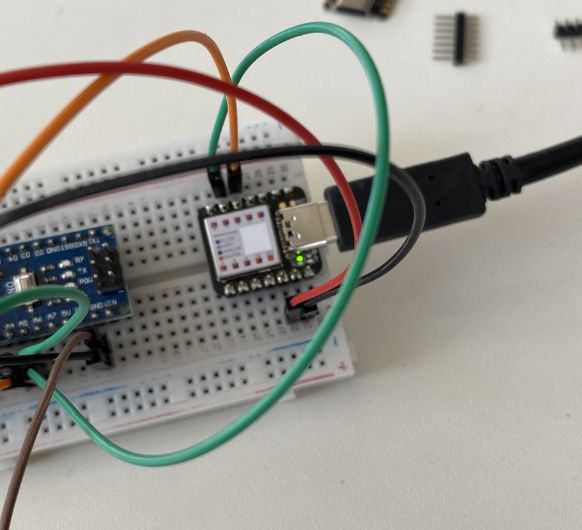 Upload the code to the first SAMD21
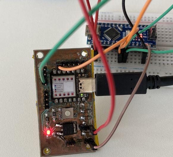 Upload to the second SAMD21 on ym selfmade pcb
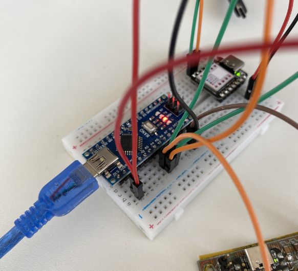 Upload the master code to the Nano
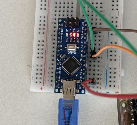
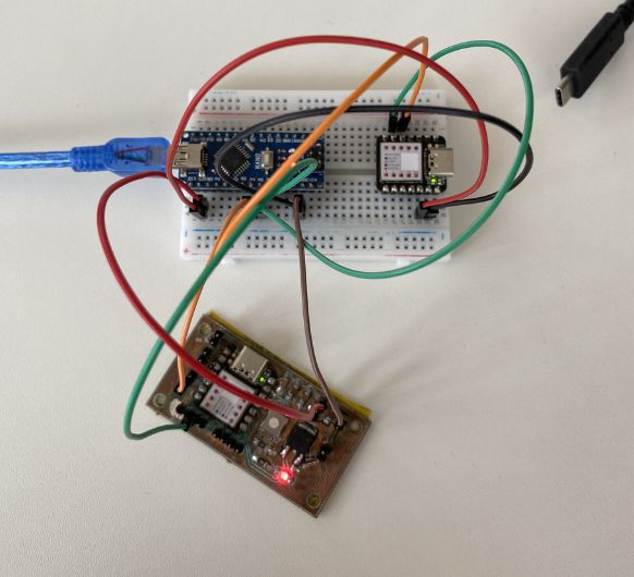 Here is the full connection
I2C communication between Arduino Nano and SAMD21
For more infor on my selfmade board (SAMD21) click here: Electronics design, Electronics production,
Embedded programming
For the second part of the assignment, I will make the Arduino
Nano (master) send a message to the XIAO SAMD21 (slave) and also request a message from the
SAMD21 in return. This will demonstrate bidirectional communication between the two boards using
I2C.
XIAO SAMD21 Code (Slave):
#include

	#define SLAVE_ADDRESS 0x31

	char messageFromMaster[16];

	void setup() {
		Wire.begin(SLAVE_ADDRESS); // Join I2C bus as a slave with address 0x31
		Wire.onRequest(requestEvent); // Attach event handler for master request
		Wire.onReceive(receiveEvent); // Attach event handler for receiving data

		// Initialize message buffer
		strcpy(messageFromMaster, "No Message");
	}

	void loop() {
		// Nothing to do here
	}

	void requestEvent() {
		// Send a message to the master
		char *data = "Hello Master";
		Wire.write(data);
	}

	void receiveEvent(int bytes) {
		// Read the message sent by master
		int i = 0;
		while (Wire.available() && i < 15) {
		messageFromMaster[i++] = (char)Wire.read();
		}
		messageFromMaster[i] = '\0'; // Null terminate the string
	}
char messageFromMaster[16]: This line declares a character arraymessageFromMasterwith a size of 16. It will be used to store the message received from the I2C master.-
void setup():Wire.begin(SLAVE_ADDRESS): This line initializes the Wire library and joins the I2C bus as a slave device with the specifiedSLAVE_ADDRESS.Wire.onRequest(requestEvent): This line attaches an event handler functionrequestEventto the Wire library. TherequestEventfunction will be automatically called whenever the I2C master requests data from the slave device.Wire.onReceive(receiveEvent): This line attaches an event handler functionreceiveEventto the Wire library. ThereceiveEventfunction will be automatically called whenever the slave device receives data from the master.strcpy(messageFromMaster, "No Message"): This line initializes themessageFromMasterarray with the string "No Message". It sets a default value for the message in case no data is received from the master.
-
void loop(): -
void requestEvent(): This function is called when the I2C master requests data from the slave device.char *data = "Hello Master": This line declares a character pointer variabledataand assigns it the address of the string "Hello Master". This message will be sent to the master in response to its request.Wire.write(data): This line uses the Wire library to send thedatamessage to the I2C master.
-
void receiveEvent(int bytes): This function is called when the slave device receives data from the I2C master.int i = 0: This line initializes a counter variableito zero, which will be used to index the elements of themessageFromMasterarray.while (Wire.available() && i < 15): This loop reads the data sent by the master byte by byte until there is no more data available or the array is full.messageFromMaster[i++] = (char)Wire.read(): This line reads a byte of data from the I2C bus using the Wire library'sWire.read()function and assigns it to the next element of themessageFromMasterarray. Thei++operation increments the value ofiafter the assignment.messageFromMaster[i] = '\0': This line adds a null character at the end of themessageFromMasterarray to terminate the string and make it a valid C-string.
Arduino Nano Code (Master):
#include

	char messageFromSlave[16];

	void setup() {
		Wire.begin(); // Join I2C bus as master
		Serial.begin(9600); // Start serial communication at 9600 baud
	}

	void loop() {
		// Send a message to the slave
		Wire.beginTransmission(0x31);
		Wire.write("Hello Slave");
		Wire.endTransmission();

		delay(500);

		// Request 12 bytes from the slave
		Wire.requestFrom(0x31, 12);
		int i = 0;
		while(Wire.available() && i < 15) {
		messageFromSlave[i++] = (char)Wire.read();
		}
		messageFromSlave[i] = '\0'; // Null terminate the string

		// Print message received from the slave
		Serial.println(messageFromSlave);

		delay(1000);
	}
-
void loop():Wire.beginTransmission(0x31): This line begins the transmission to the slave device with the address 0x31.Wire.write("Hello Slave"): This line sends the message "Hello Slave" to the slave device.Wire.endTransmission(): This line ends the transmission to the slave device.delay(500): This line adds a delay of 500 milliseconds (0.5 seconds) to allow time for the slave device to process the message.Wire.requestFrom(0x31, 12): This line requests 12 bytes of data from the slave device with the address 0x31.-
while (Wire.available() && i < 15) { ... }: This loop reads the data received from the slave byte by byte until there is no more data available or the array is full.messageFromSlave[i++] = (char)Wire.read(): This line reads a byte of data from the I2C bus using the Wire library'sWire.read()function and assigns it to the next element of themessageFromSlavearray. Thei++operation increments the value ofiafter the assignment.
messageFromSlave[i] = '\0': This line adds a null character at the end of themessageFromSlavearray to terminate the string and make it a valid C-string.Serial.println(messageFromSlave): This line prints the received message from the slave device to the Serial Monitor.delay(1000): This line adds a delay of 1000 milliseconds (1 second) before repeating the loop.
In summary: In this example, the Arduino Nano sends a message "Hello Slave" to the XIAO SAMD21 and requests a message from it. The XIAO SAMD21 receives the message, and when requested, sends back "Hello Master". You should see "Hello Master" printed in the Arduino Nano's serial monitor. This example shows bi-directional communication between the Arduino Nano and the XIAO SAMD21 over I2C.
 Upload the code to the "Slave"
 Upload the code to the "Master"
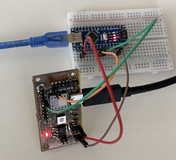 Connection overwiew.