Leen Nijim
Assignment 13
Input Devices
Task
Our assignment this week was to add an input device to our microcontroller board and program it to do something. I decided to use a DHT11 humidity sensor because I also intend on using one for my final project, albeit with a different microcontroller. But for the task at hand, using the ATtiny44 board I previously designed was not as easy as I had hoped for. In the end, I changed my plan and used a potentiometer joystick module to control the LED on my board.
What You Need
- ATtiny44 microcontroller board.
- Potentiometer joystick module.
- ISP programmer board (FabTinyISP).
Files to Download
Hero Shot
Group Assignment
For our group assignment this week, please click here.
What Did Not Work
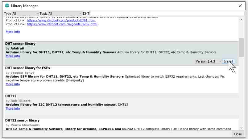
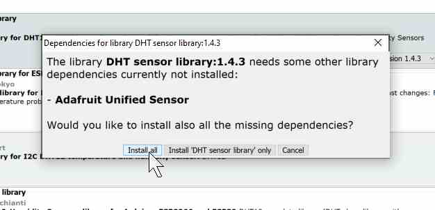
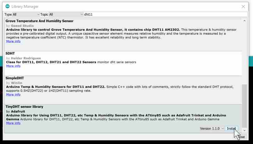
First off, I downloaded the adruino library for the DHT11 module.
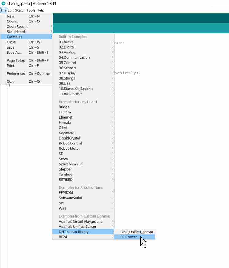
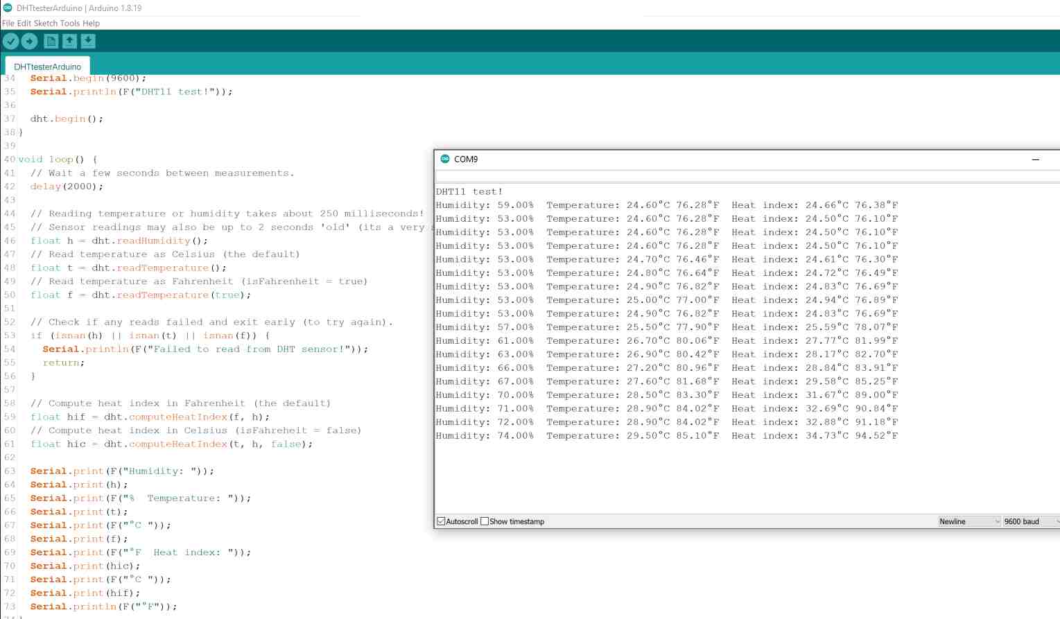
And ran it using an Arduino Uno board to make sure that everything works.
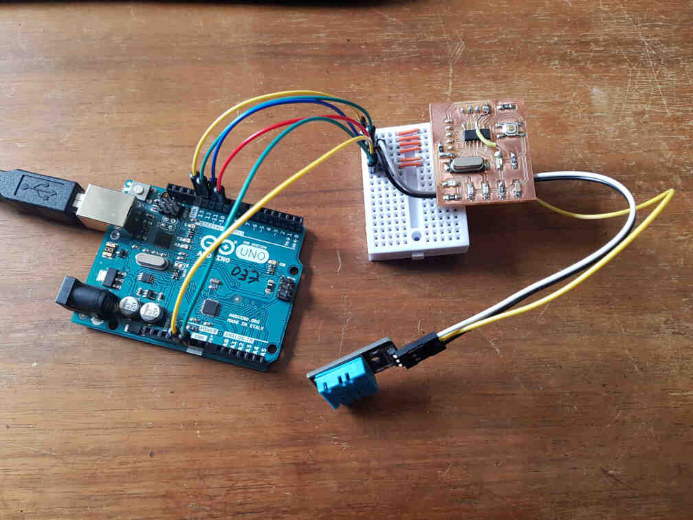
Then I connected it to my ATtiny44 board and used the Arduino Uno as an ISP programmer.
But then I quickly realized that the library I downloaded earlier is too big for my microcontroller, so I downloaded a lighter version.
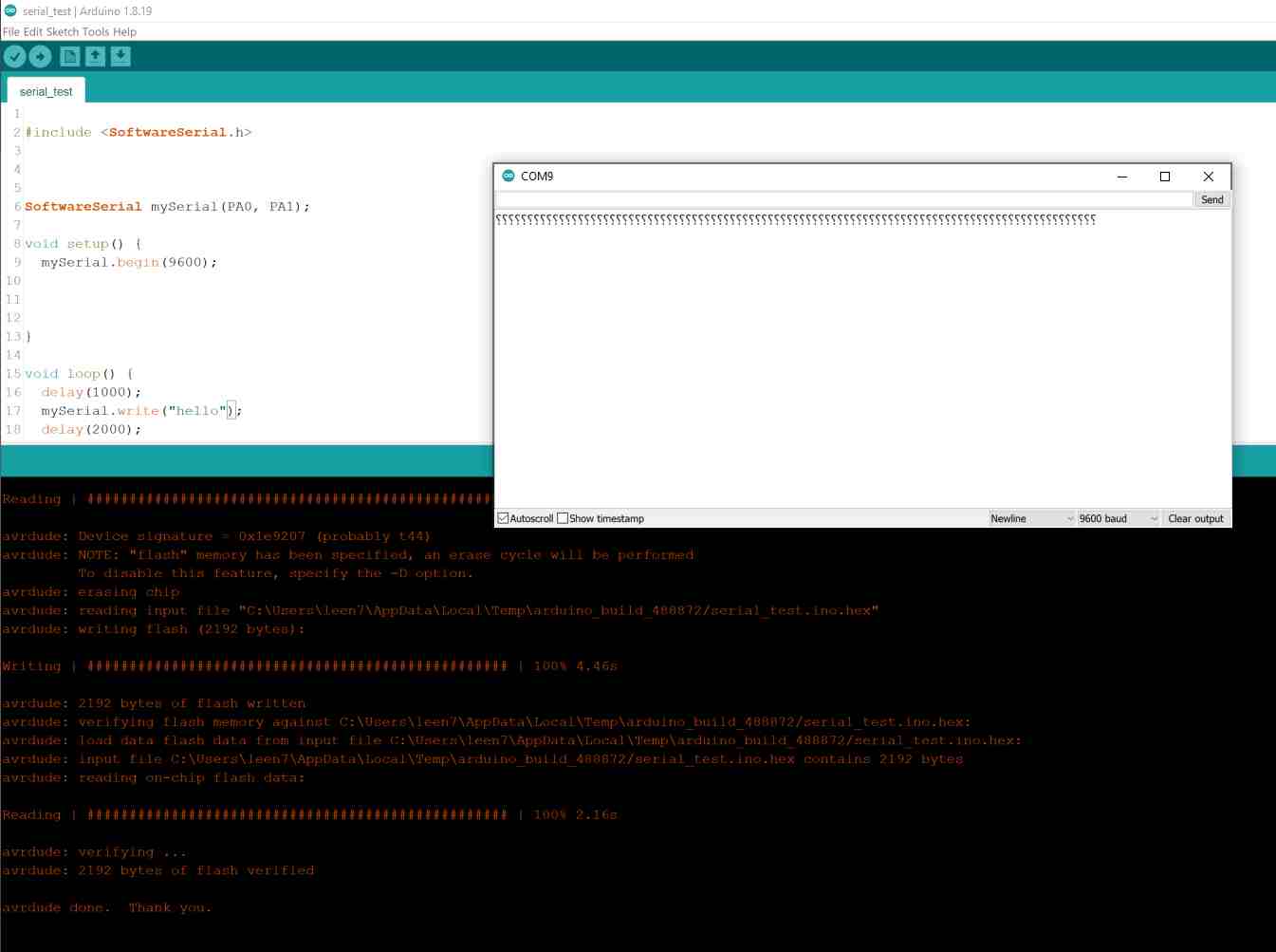
I also downloaded a software serial library since the ATtiny44 does not have dedicated serial communication pins, but I did not get the results I was hoping for.
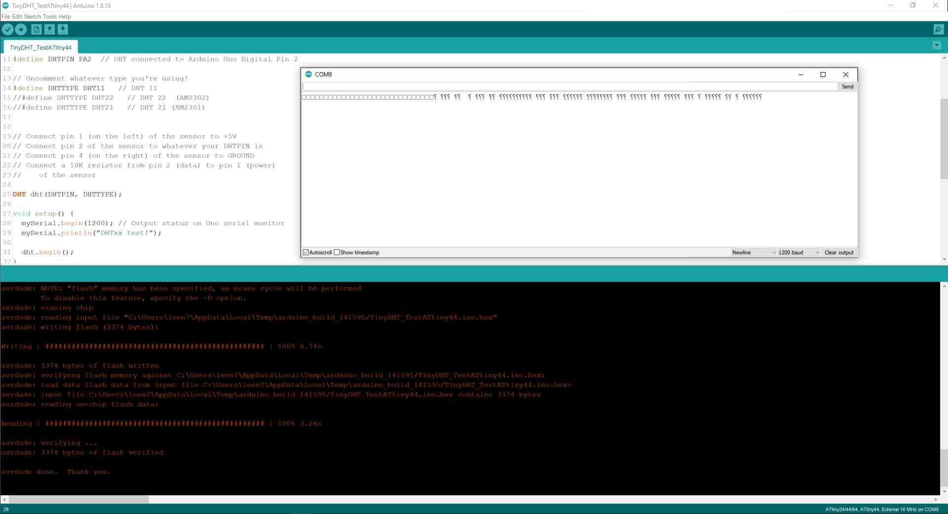
I then checked whether the serial communication is working at all, but was not successful either.
At this point I was ready to give up on the DHT11 sensor, since I will be using it with a different microcontroller for my final project anyway.
What Did Work
On my second try at this assignment, I had already had a functional ISP programmer and decided to just go for a simple potentiometer input signal to control the on-time of a blinking LED. This will emulate a humidity reading input that actuates the dryer fan I am planning to use for my project.
Here is my gang of FabTinyISP, hello ATtiny44 board, and potentiometer joystick module.
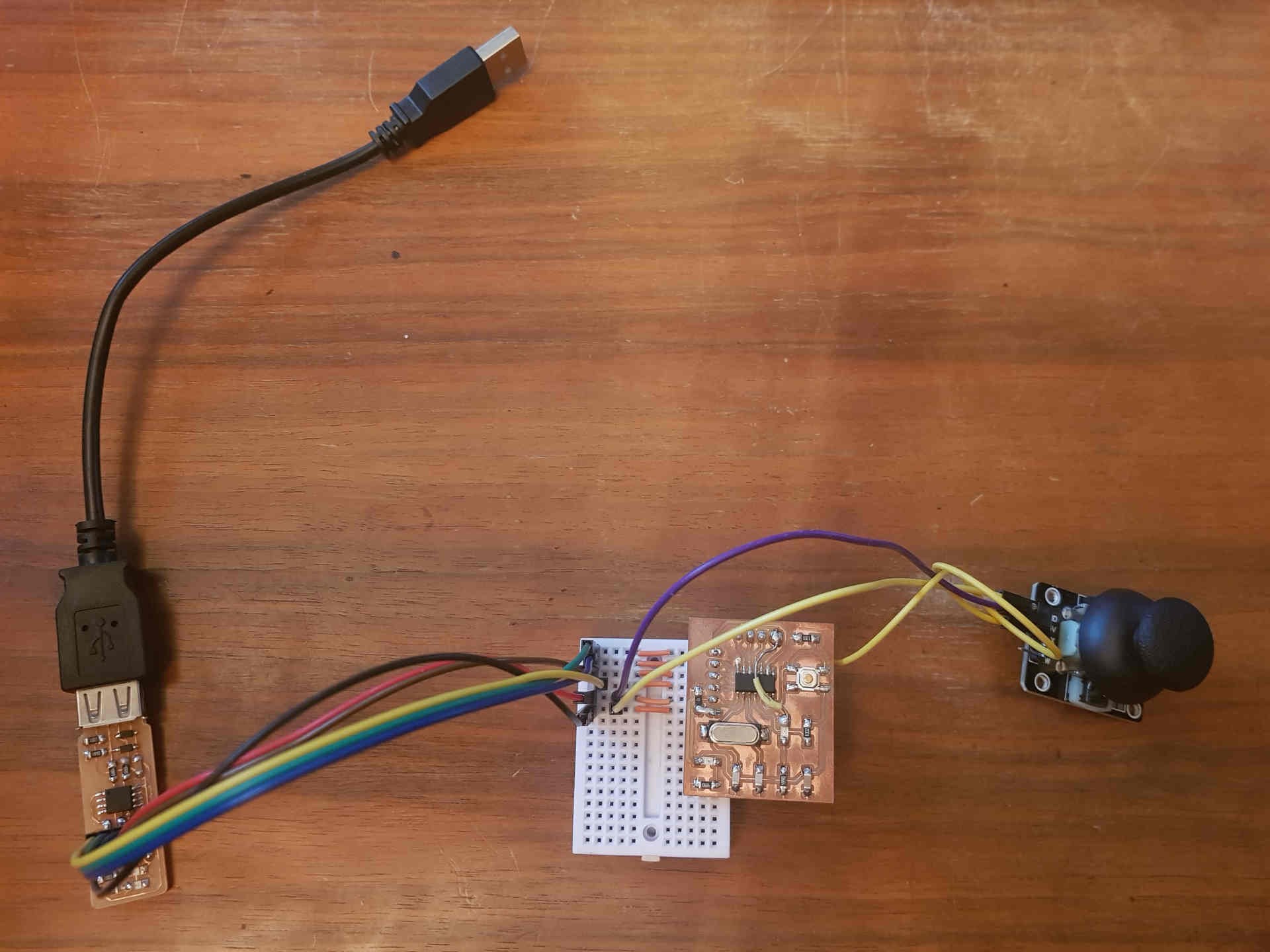
And they are connected as follows:
| FabTinyISP | ATtiny44 | Joystick Module |
|---|---|---|
| Pin VCC | Pin 1 (VCC) | Pin +5V |
| Pin RST | Pin 4 (RESET) | - |
| Pin MOSI | Pin 7 (MOSI) | - |
| Pin MISO | Pin 8 (MISO) | - |
| Pin SCK | Pin 9 (SCL) | - |
| - | Pin 12 (PA1) | Pin VRX |
| Pin GND | Pin 14 (GND) | Pin GND |
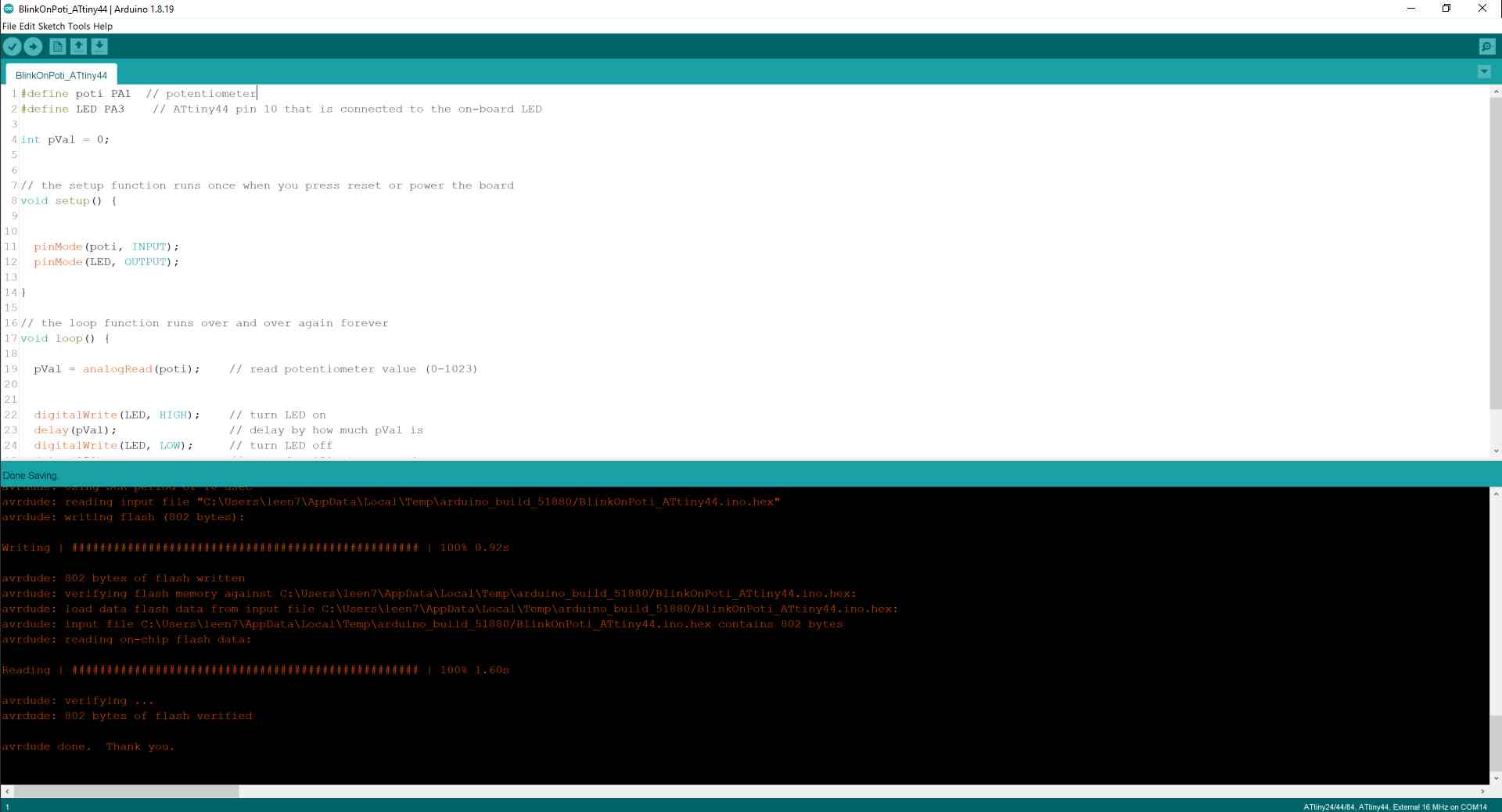
Here is the code I wrote:
#define poti PA1  // potentiometer
#define LED PA3    // ATtiny44 pin 10 that is connected to the on-board LED

int pVal = 0;


// the setup function runs once when you press reset or power the board
void setup() {


	pinMode(poti, INPUT);
	pinMode(LED, OUTPUT);

}

// the loop function runs over and over again forever
void loop() {

	pVal = analogRead(poti);    // read potentiometer value (0-1023)

	digitalWrite(LED, HIGH);    // turn LED on
	delay(pVal);                // delay by how much pVal is
	digitalWrite(LED, LOW);     // turn LED off
	delay(250);                 // wait for 250 microseconds
}
In the code, I declared the potentiometer as an input, and the LED as an output. I then ran the main loop to continuously read the potentiometer value as an analog reading (from 0 to 1023), and use that number to keep the LED on for that certain amount of time (in milliseconds), and then I turn off the LED for further 250 milliseconds. This means that the lower the potentiometer value is (joystick moved to the left), the faster the LED blinks, and vice versa.
Here it is working!