Leen Nijim
Assignment 5
Electronics Production
Task
This week we had to read a bit about microcontrollers and choose an appropriate programmer for the one we decide to use for our final project. Since I am still not completely sure about which one I’ll be using, I decided to go with the advice of our local instructor and make his FT230x-UPDI board.
What You Need
- Access to a PCB mill.
- A couple of PCBs.
- Access to a soldering station.
Hero Shots
Group Assignment
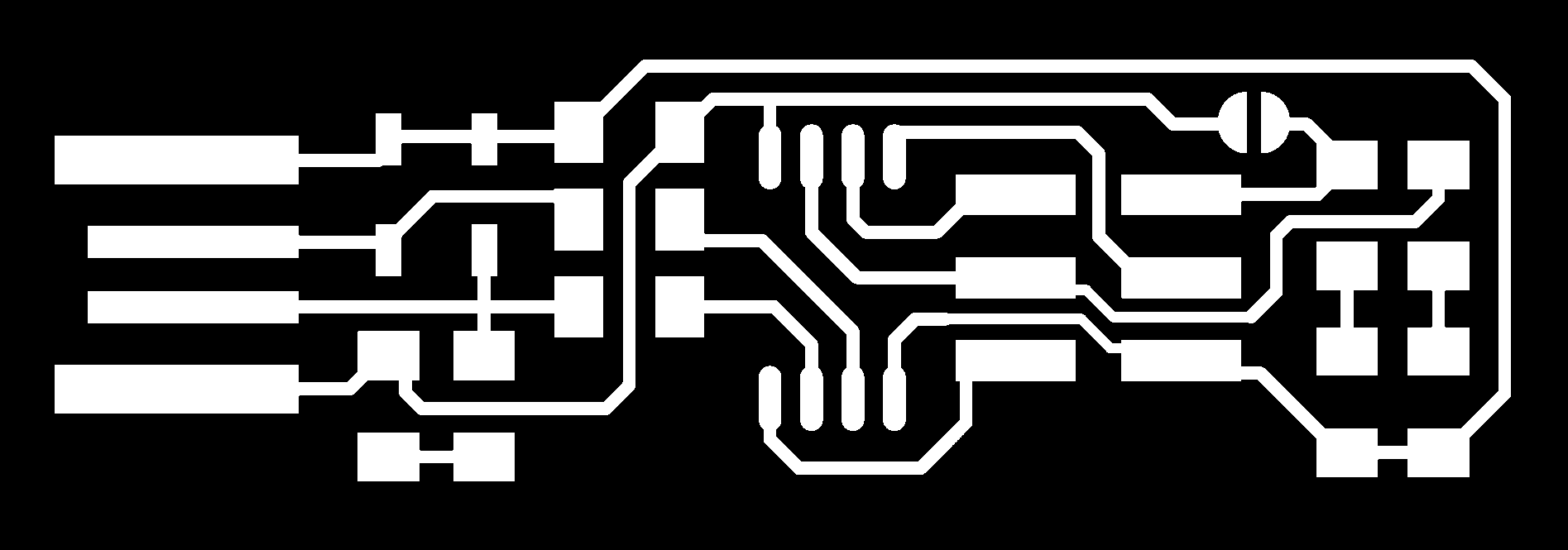
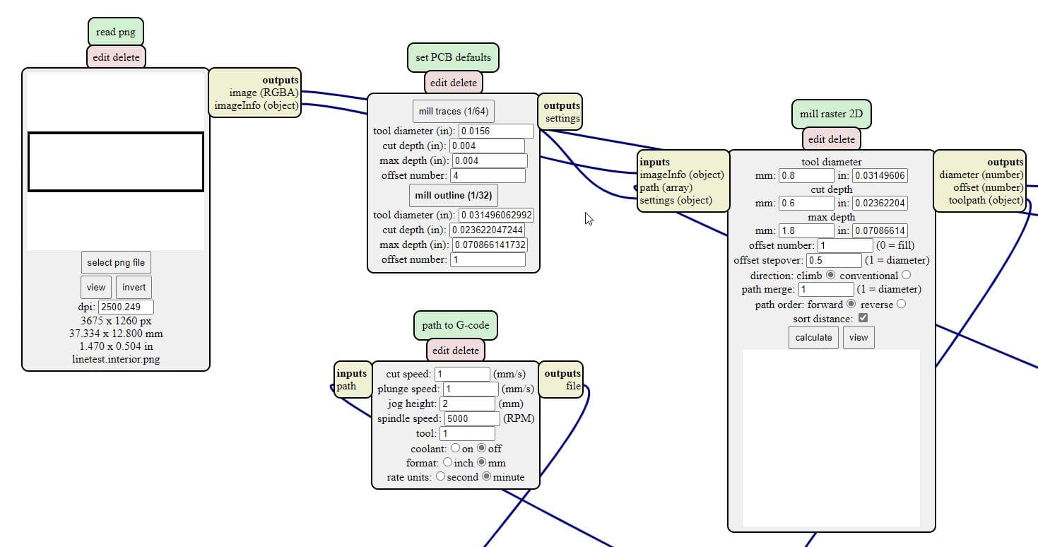
For our group assignment this week, please click here. My part was to do a line test on our Genmitsu using the 0.2-0.5 mm end mill bit.
Here are the mods settings I used for the traces:
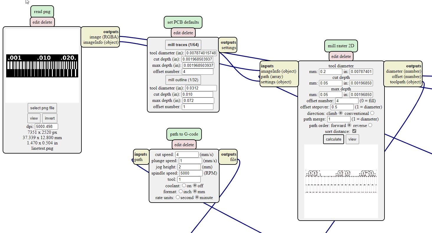
Here are the settings for the cutout:
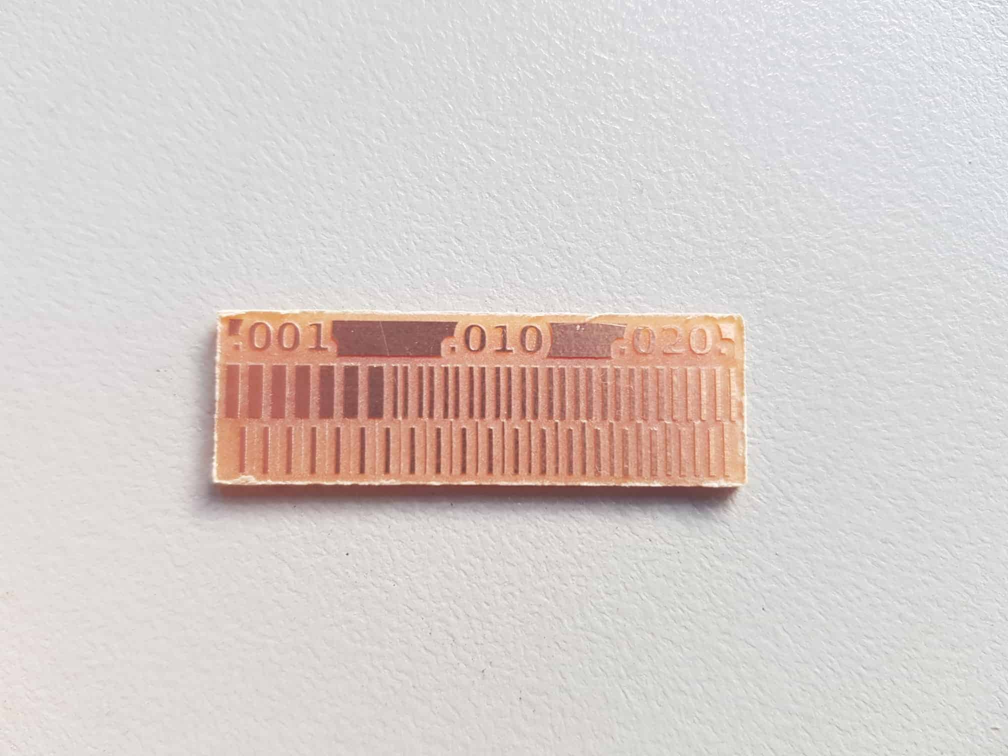
And here are the results :).

In the end somehow the traces got cut along the middle line and did not look like I expected it to, which was when I realized I made a logical mistake with the black and white traces image and that I should have inverted it.
FT230x-UPDI Board
To create a gcode for the milling machine to mill out the board, I need to either have an SVG or a png file. This file is then fed into mods. This tutorial is very easy to follow for preparing the gcode.
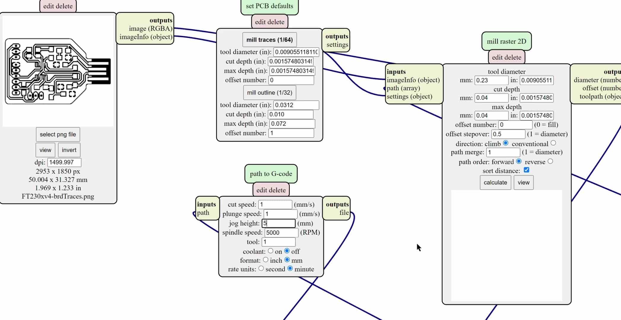
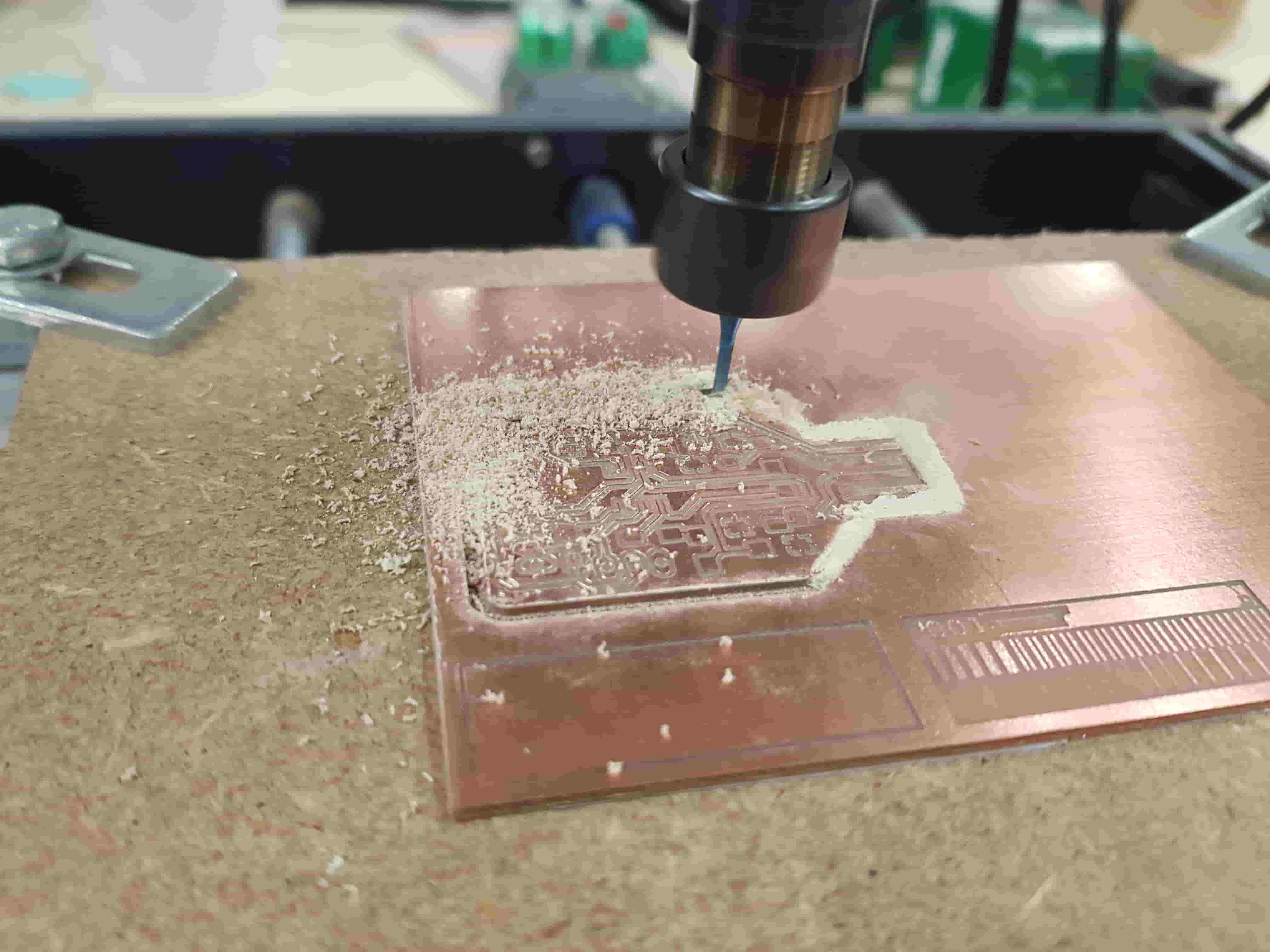
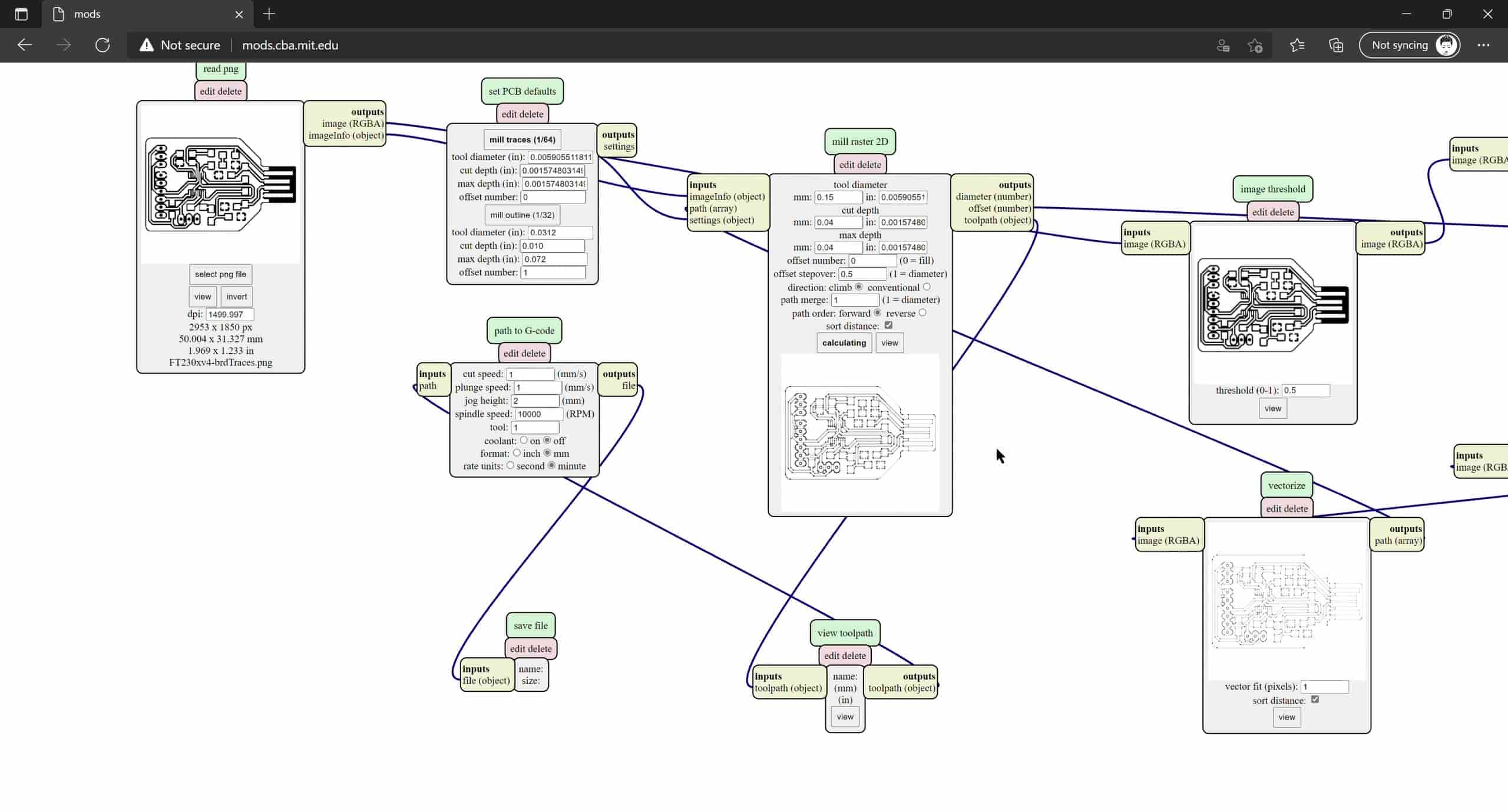
Milling Traces
For my first attempt at cutting the circuit traces with the 0.2-0.5 end mill bit, I used the following settings:
From here I got the gcode to feed into our Genmitsu. And for that I found this quick guide to be really useful. I didn’t use their method of finding the z-axis zero, though. I depended on my eyes to check at which height the end mill starts to create powder chips and its rotation noise changes.


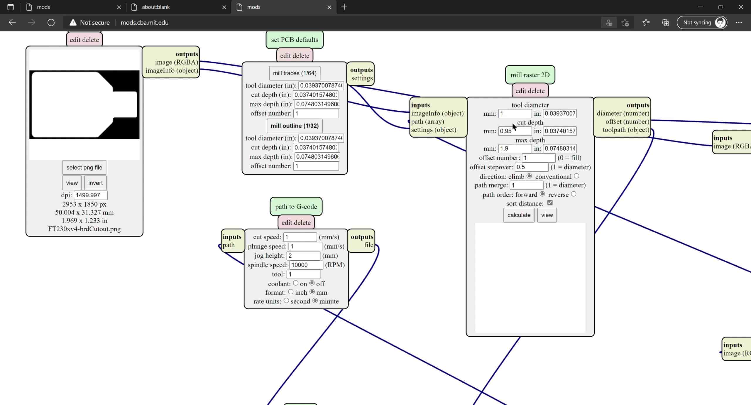
Milling Cutout
For the cutout, I had to change my tool to the 1mm end mill bit. Parallel to that, I created my gcode using mods again but with these settings instead:
And now to the cutting in Candle.
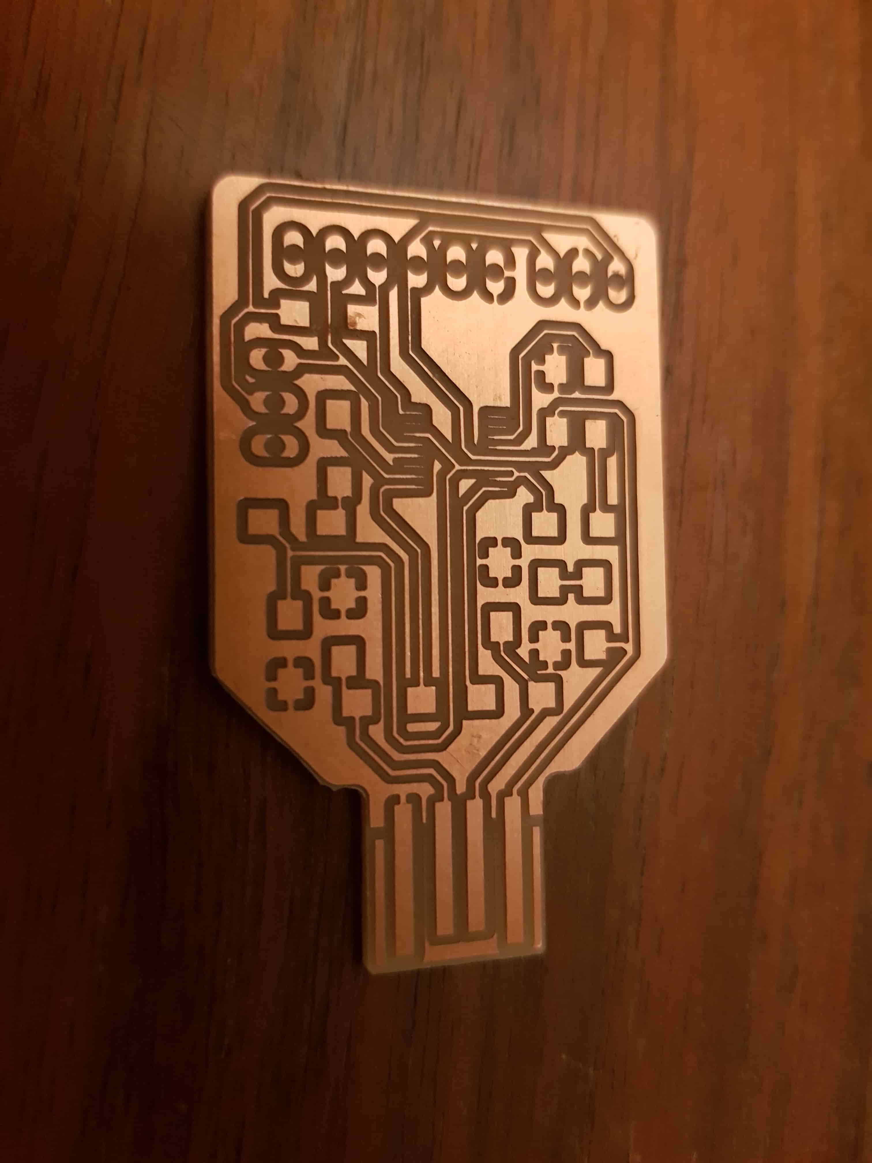
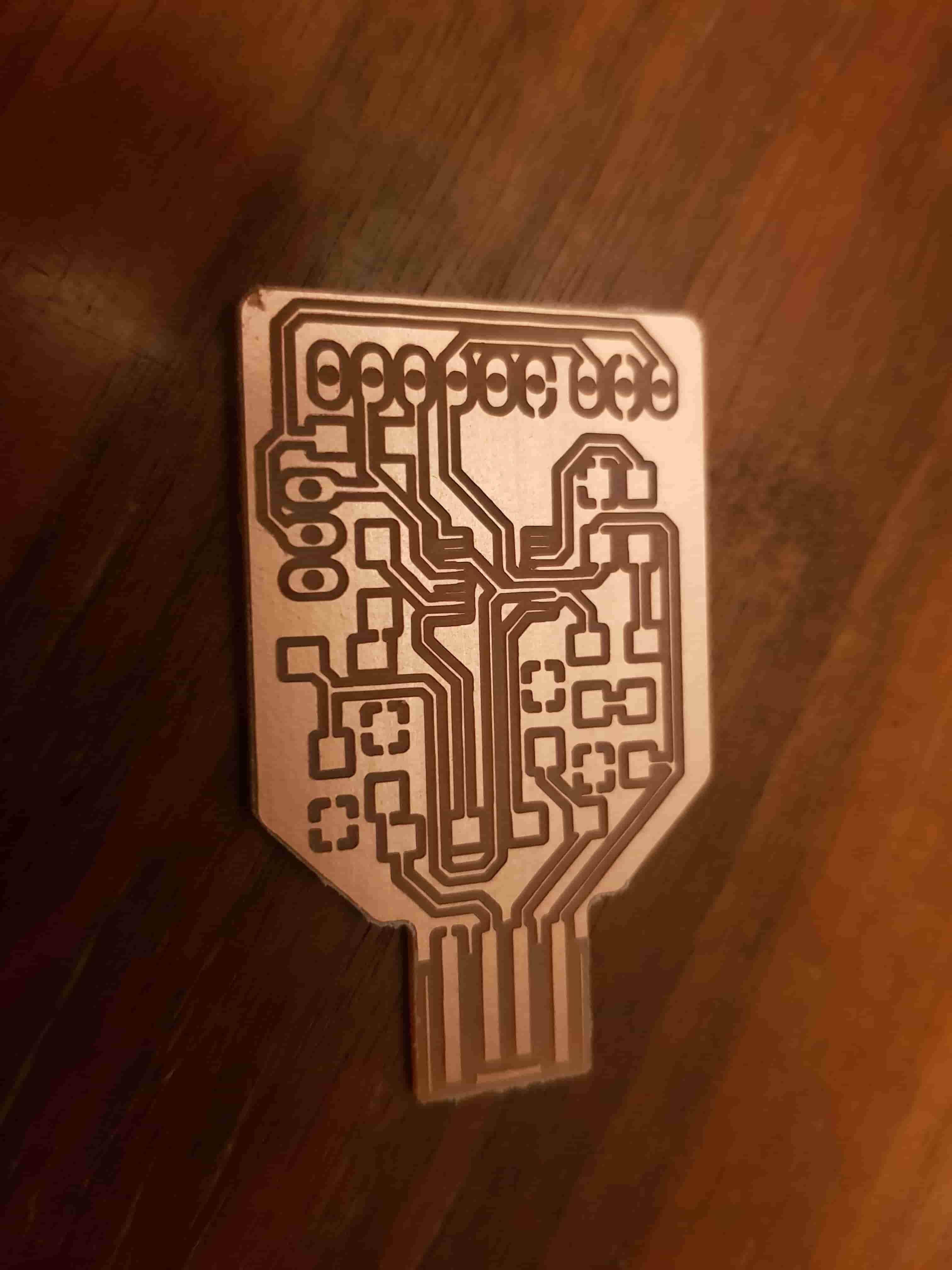
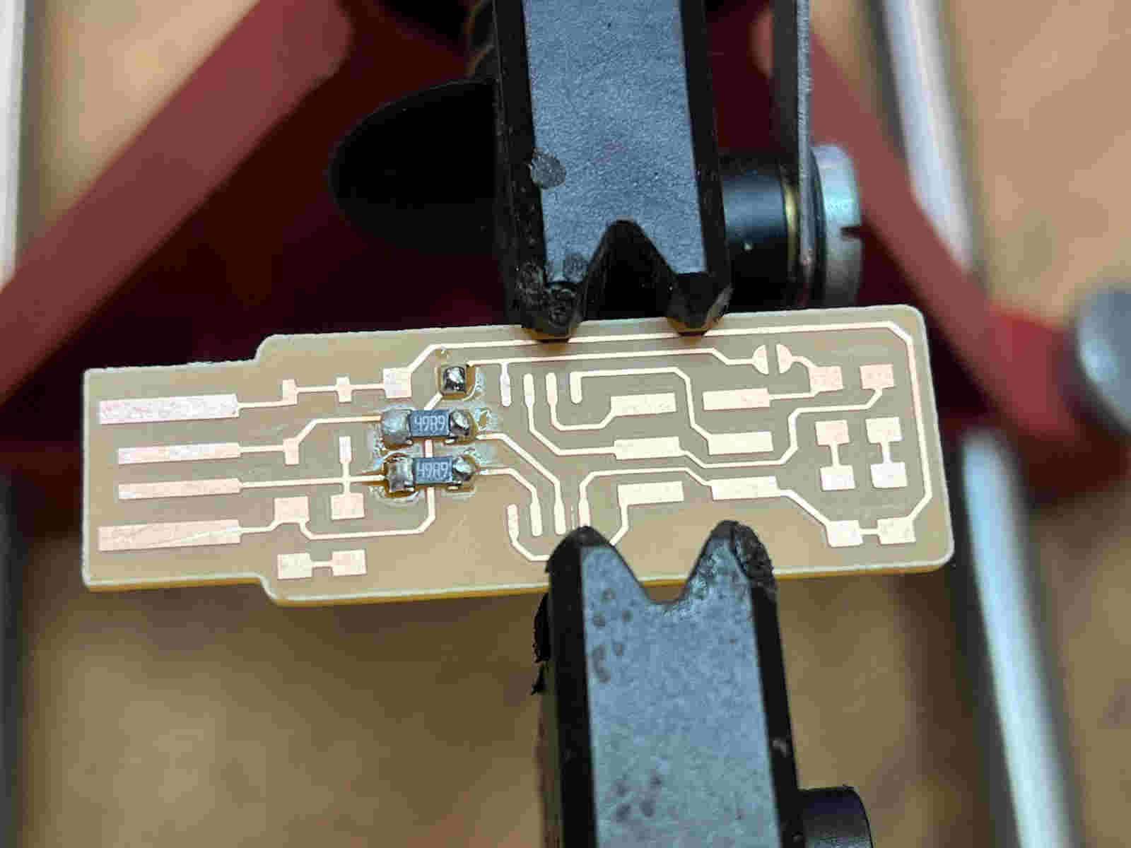
After a hard time fighting the board to take it off of the sacrificial wooden board, I was able to remove my PCB with the edge of a metal ruler. To my disappointment, the traces on my board were very thin and for some parts, especially where the FT230XS chip goes, I don’t think they’re easy to solder components to.
So I then tried milling another time but using the 0.1-0.3 end mill bit. I still had to generate the gcode for the traces part again, but for the cutout the gcode remained unchanged. Here are the setting I used for the new traces job:
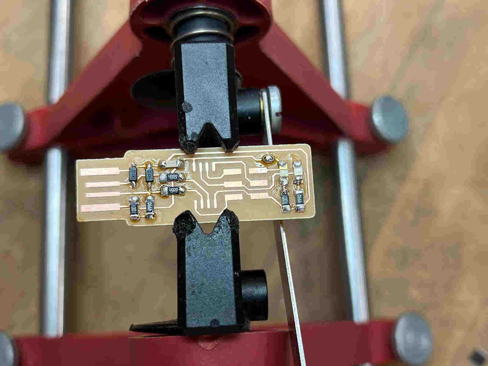
An hour and a half later I ended up with very similar, if not worse, results to the first board:
So by now I think my two main problems are that my stock PCB board is not completely flat on the bed, and that my cutout tool was digging too deep into the PCB so that the surviving traces are too thin to be used confidently.
FabTinyISP Board
Given that we still don’t have the electronic components in our lab yet to stuff my programmer PCB, I decided to mill the FabTinyISP board on our Roland as well, because from the research I was able to do, it looks like one of the old ATMEGA microcontrollers would be enough for my final project application, and so I could use a FabTinyISP to program it.
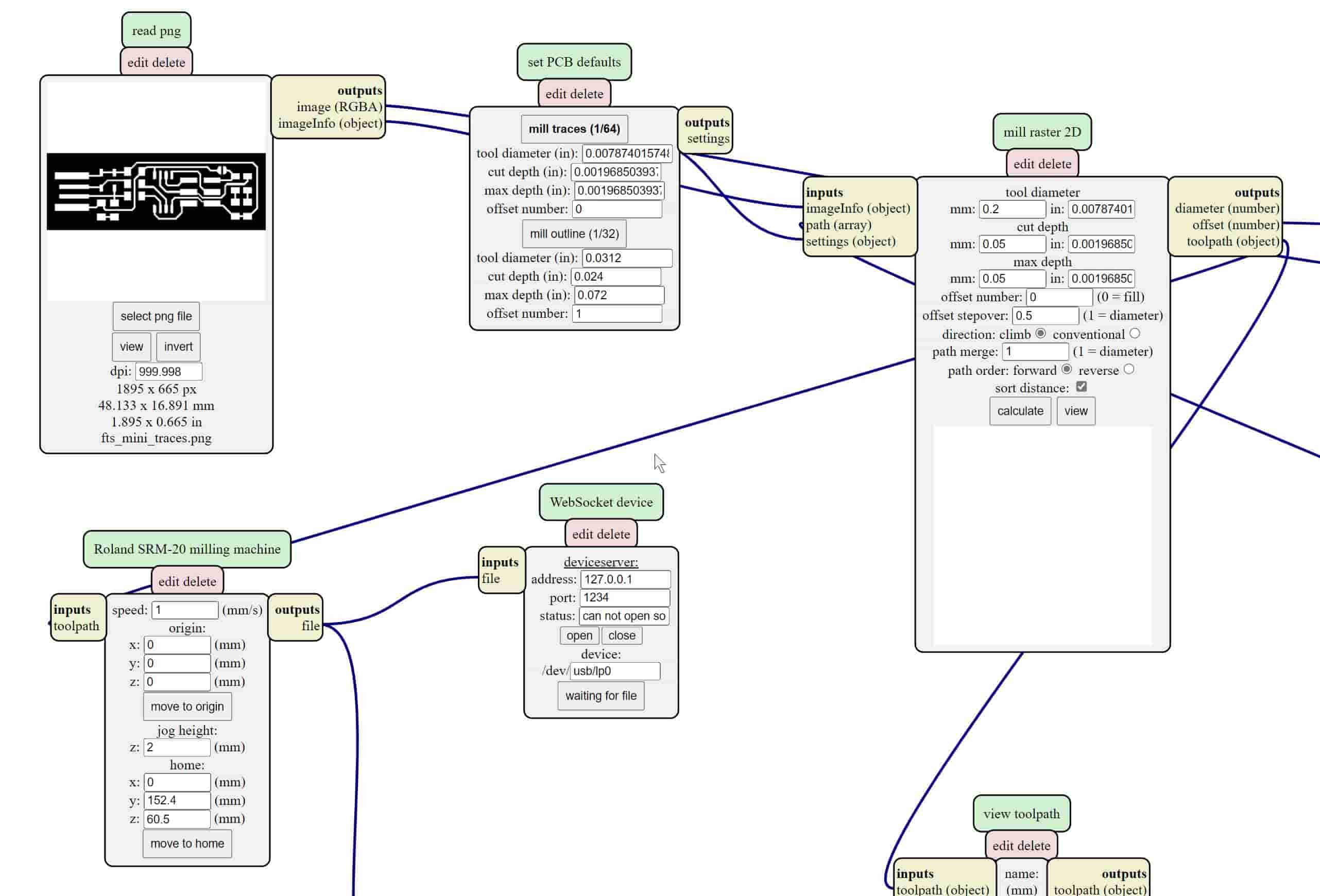
Milling Traces
Here are the traces gcode settings I used:
Mid-milling view using the View function

Getting there...
-min.jpeg)
Milling Cutout
And here are the cutout gcode settings:

I am pretty pleased with how the traces turned up, as they are all of adequate width and no apparent trouble should be in sight.

Stuffing FabTinyISP
We finally got access to the needed electronic components so I collected both the ones for the FT230x-UPDI board and the FabTinyISP board. It was a pretty useful practice to write down the components as a list and place them on a double-sided tape next to their names since it is sometimes hard to identify some of them once out of their respective packaging.
.jpeg)
And then it was time to set up my soldering station. As recommended, I used some aceton to clean up the board before proceeding to populate it.

Next was to solder the components in a logical order. The easiest way is to place the smallest ones (height-wise) first and go from the inside of the board outwards. To place a single component, I added some solder onto the first pad, soldered the component from one side onto that pad, then soldered the other terminal onto the other pad, and if necessary I then went back to the first pad and made sure it was soldered properly.
.jpeg)
Same thing on the other side.
Then it was time for the microcontroller. I used a pair of tweezers to place it properly, then soldered one corner and then another to the board to keep the package in place for the whole procedure.
.jpeg)
.jpeg)
Then a none-obvious trick: I applied a load of solder all across the pins, then used the solder wick and the soldering iron to remove the excess solder and just keep enough to have the pins attached properly to their traces.
.jpeg)
.jpeg)
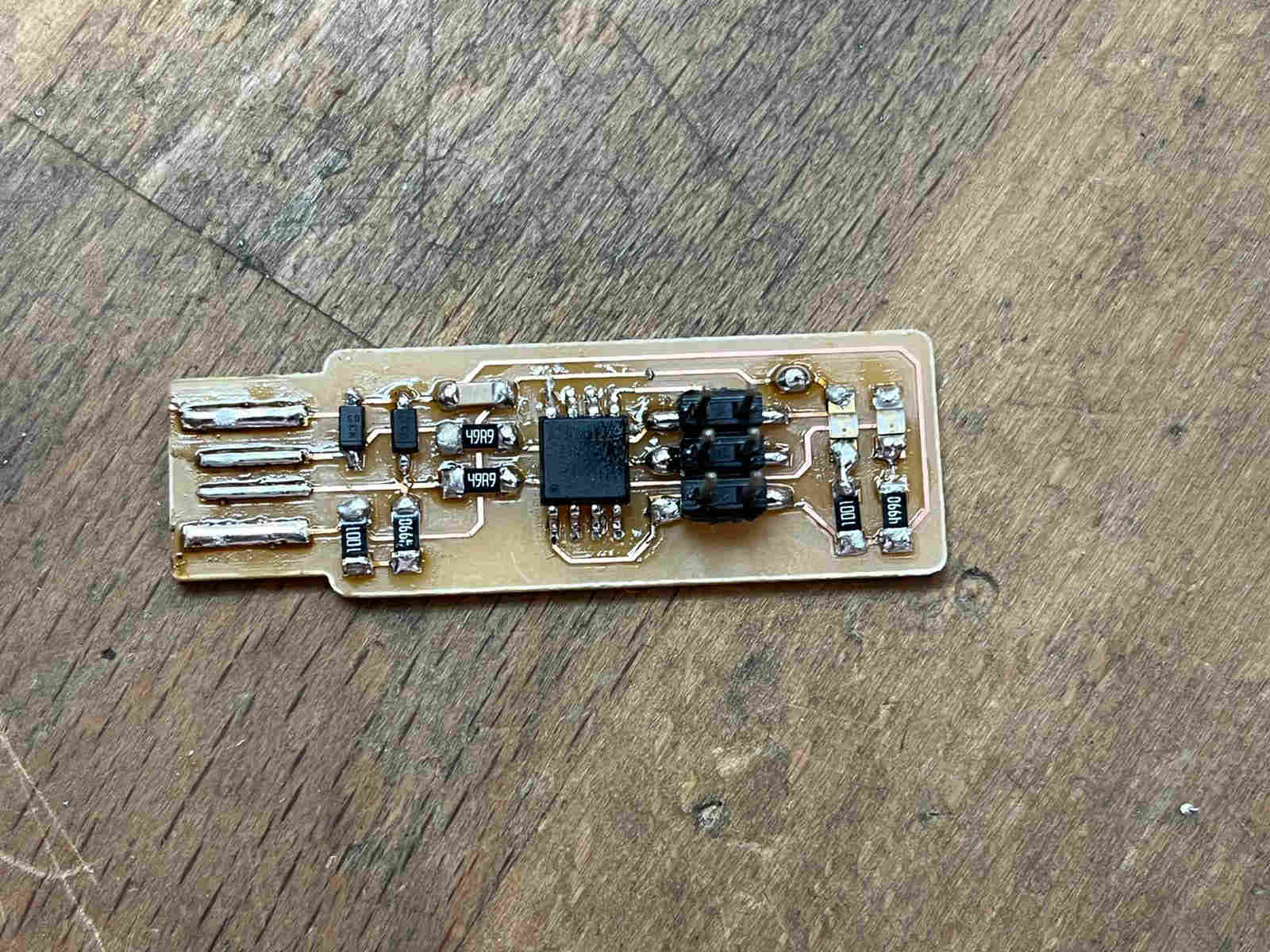
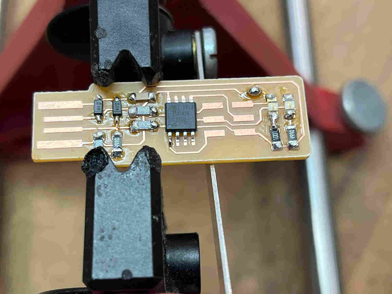
And here is the FabTinyISP fully populated.
The last step was to check whether all components have been soldered properly by doing a continuity text on all terminals using the multimeter.

Testing the Board and Awarding it the Programmer Privileges
I should first start this section by saying that it has not been the most straight-forward task to program the FabTinyISP on a Windows machine. With that said, I need to give credit to the available online tutorials and to my two fabmates Roland and Aaron, since their documentation helped me double-check my work and gave me the tips I needed to successfully program my programmer.
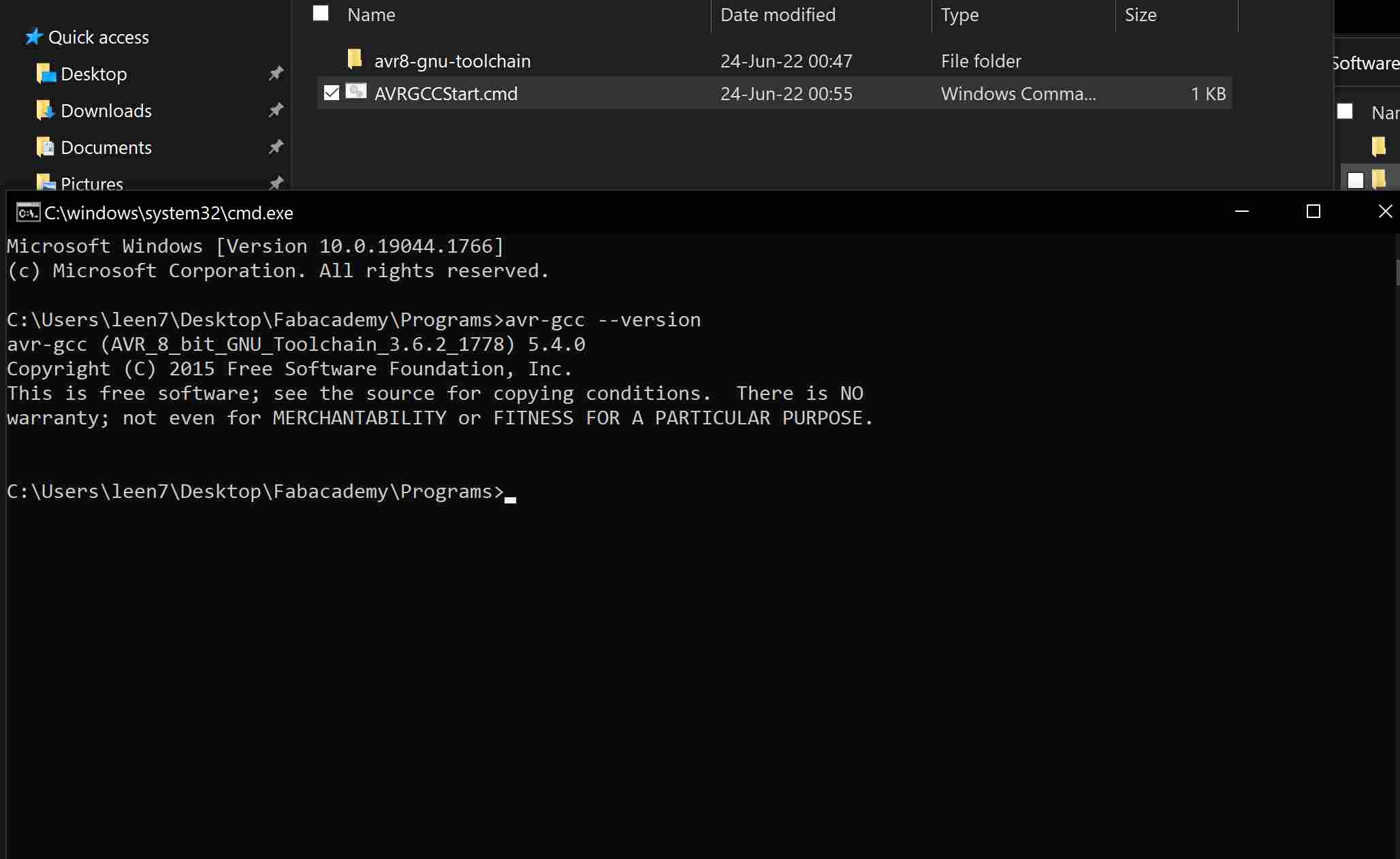
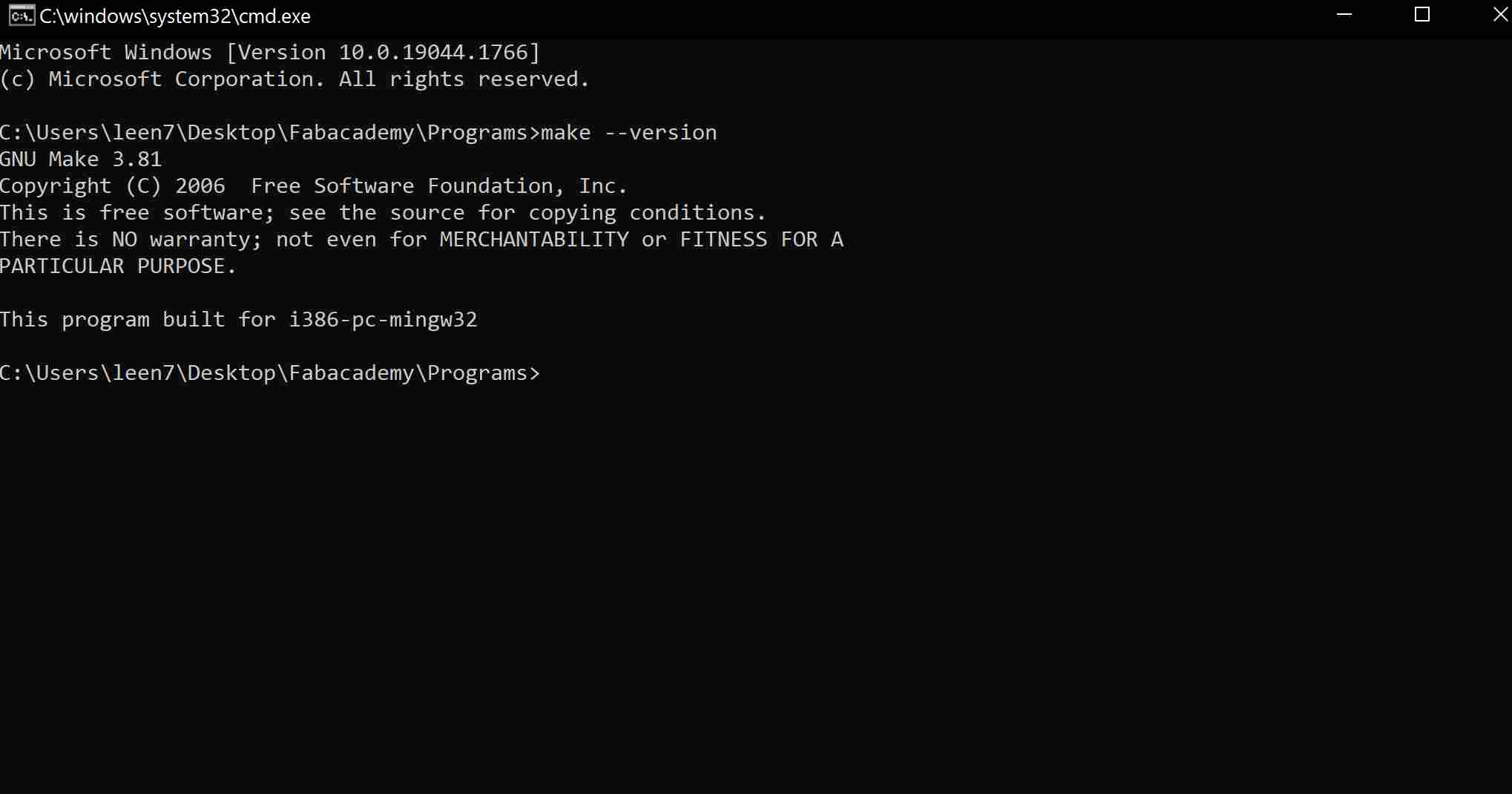
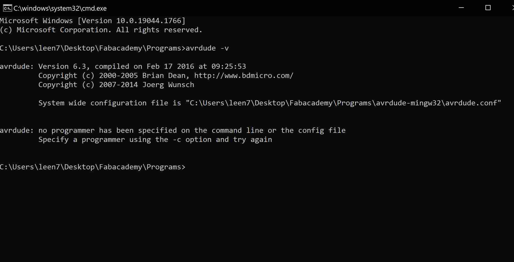
The first thing I needed to do is install the various software tools needed for the task. For that I followed this tutorial, and here are my three checks that the computer was able to call on the software I installed:
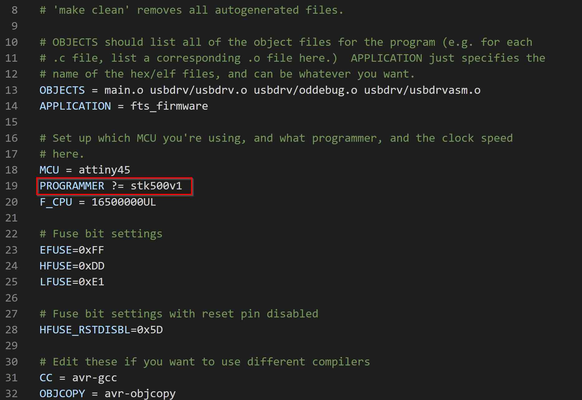
After that I needed to prepare my make file as instructed here. So I set up an Arduino Uno board as an ISP programmer and checked for the programmer details when used to program another board.

I then downloaded the firmware according to the tutorial and updated the make file accordingly.

And so when everything was ready, I went ahead and ran the make flash command to flash the program onto my board.

And then after I made sure that it all worked nicely, I was ready to blow the reset fuse and convert my board into an ISP programmer using make rstdisbl.

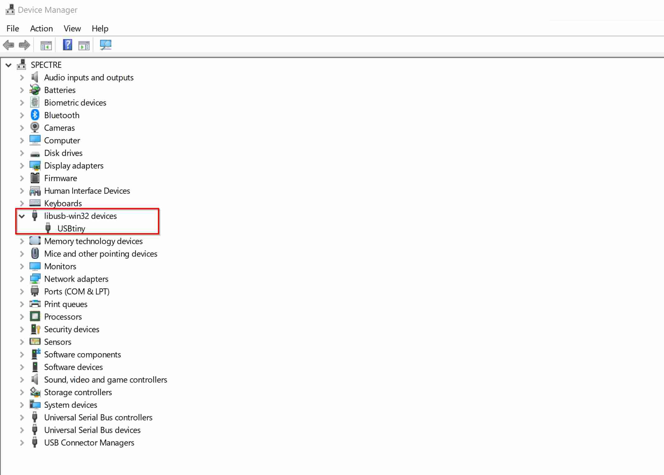
After that, I unplugged it from the Arduino Uno board that I was using as the programmer, and connected it directly to my machine and made sure it showed up (I had to install the drivers from Adafruit first, though).
And then it was time for testing. I used my FabTinyISP programmer to program the Arduino Uno board to blink its built-in LED. Success!!