Leen Nijim
Assignment 14
Networking and Communications
Task
Our assignment this week was to create a communication network between different nodes. I chose to make use of the I2C wired communication protocol to send and receive sensor data from one microcontroller board and use it to drive LEDs on another microcontroller board.
What You Need
- ATtiny44 microcontroller board.
- ATMEGA328P microcontroller board.
- An ISP programmer board (Arduino Uno in this case).
- A flame sensor module.
Files to Download
Hero Shots
Group Assignment
For our group assignment, please click here.
The Circuitry
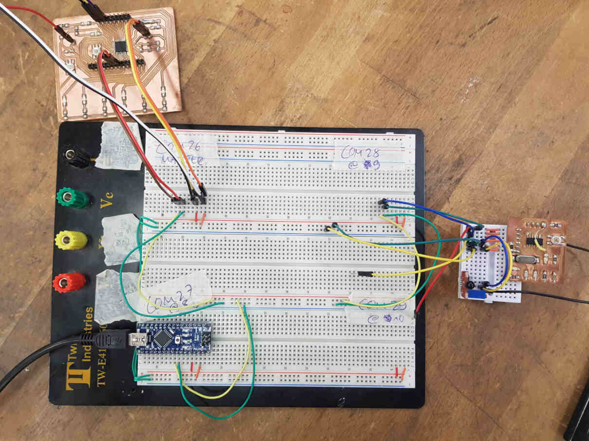
For this week, I used the board I made in Week 7 to read sensor data from this flame detector module, and used an Arduino Nano board to act as an I2C master to coordinate data communication to another node and actuate its 6 LEDs.
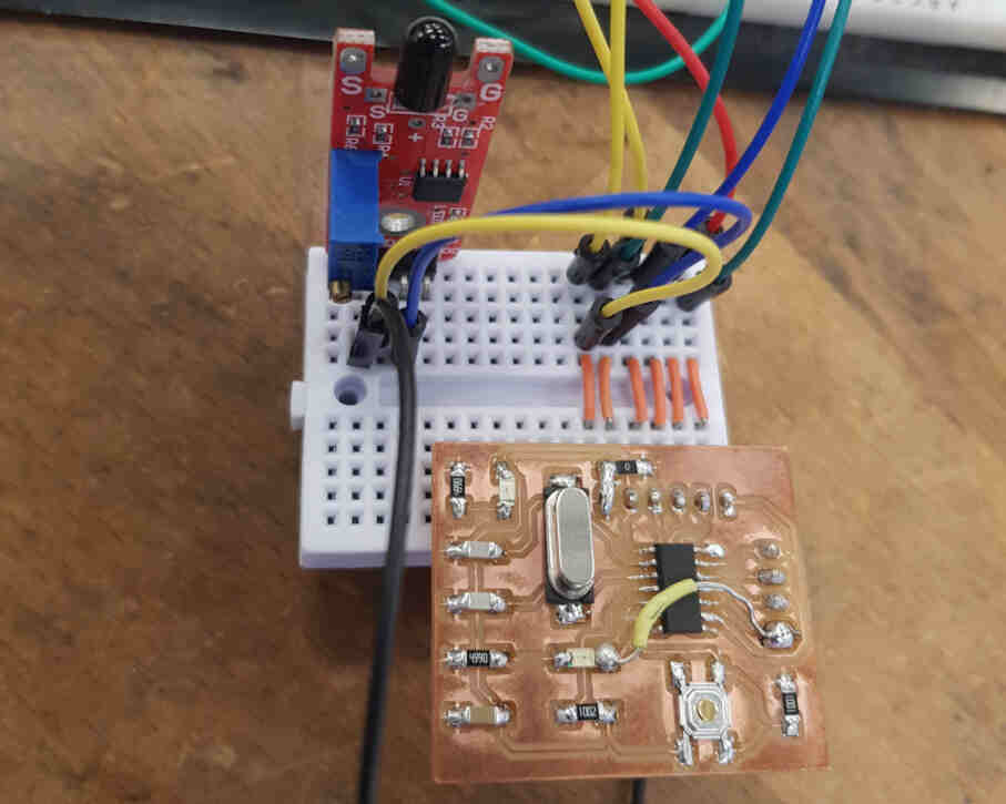
This is the sensor module that I used:

And this is how I connected it to my ATtiny44 board and then the board to the network:
| Arduino Nano | ATtiny44 | Flame Detection Module |
|---|---|---|
| Pin 5V | Pin 1 (VCC) | Pin + |
| Pin GND | Pin 14 (GND) | Pin GND |
| Pin A4 | Pin 7 (SDA) | - |
| Pin A5 | Pin 9 (SCL) | - |
| - | Pin 12 (PA1) | Pin AO |
Here is my board connected to the sensor and network.
The Code
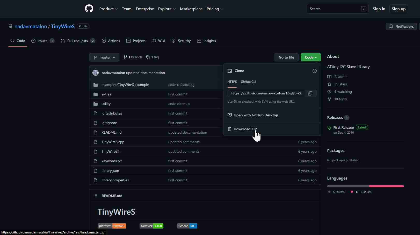
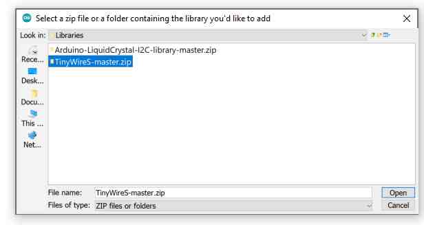
Before I started with writing the ATtiny44 board code, I had to download the I2C library for this microcontroller since according to my fabmate Roland, the built-in Wire arduino library does not work nicely for it. For that I went to this page.
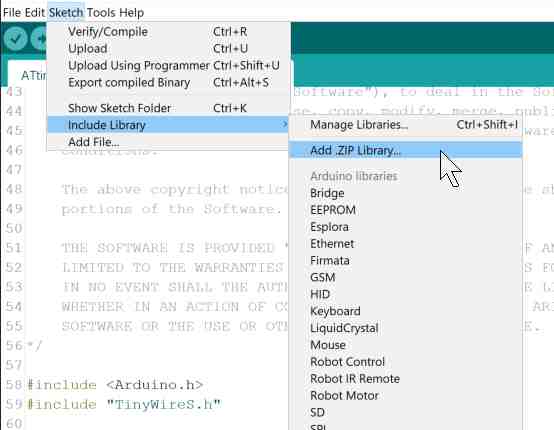
And this is how I imported it to arduino.
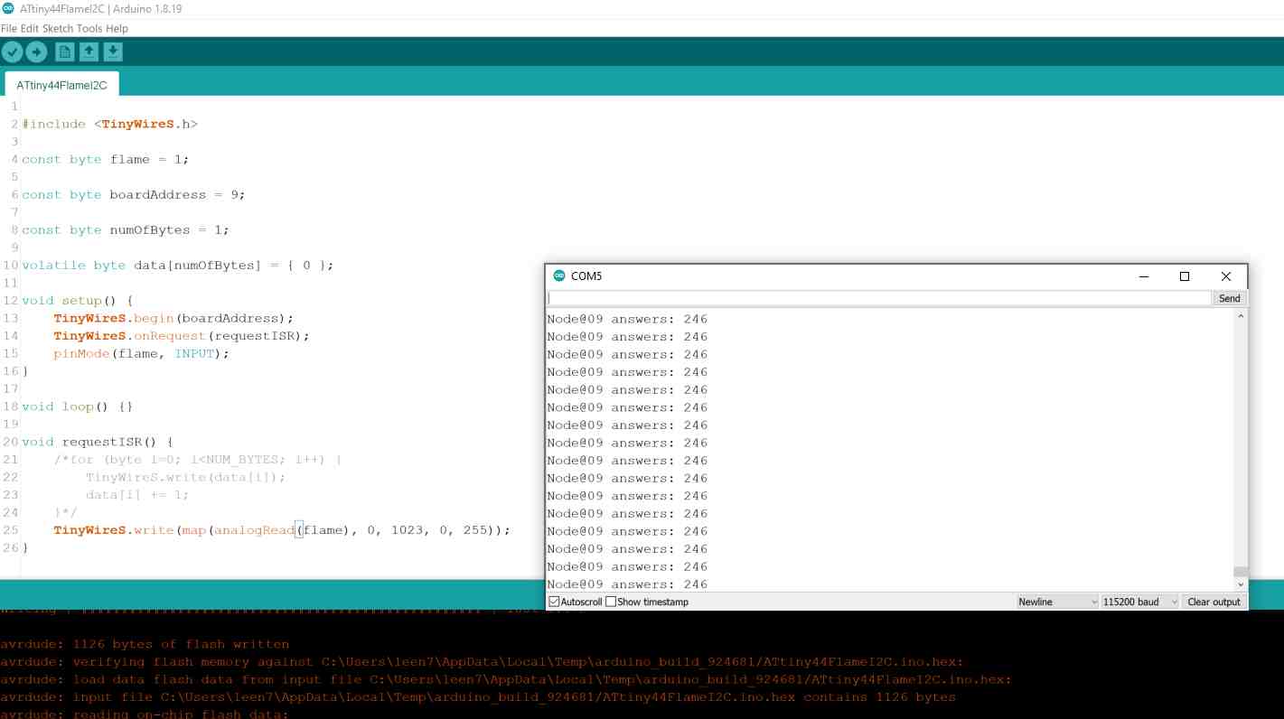
I then went to File > Examples > TinyWireS > TinyWireS_example > ATtiny84A_Slave and tried to understand how this library works. After that I was able to write a simple code that reads the data from the flame sensor module and sends it on the I2C bus.
#include <TinyWireS.h>

const byte flame = 1;

const byte boardAddress = 9;

const byte numOfBytes = 1;

volatile byte data[numOfBytes] = { 0 };

void setup() {
	TinyWireS.begin(boardAddress);
	TinyWireS.onRequest(requestISR);
	pinMode(flame, INPUT);
}

void loop() {}

void requestISR() {

	//for (byte i=0; i < NUM_BYTES; i++) {
		TinyWireS.write(data[i]);
		data[i] += 1;
	}*/
	TinyWireS.write(map(analogRead(flame), 0, 1023, 0, 255));
}
Meanwhile, I also uploaded the code for the master microcontroller on the I2C bus to scan for devices from File > Examples > Wire > i2c_scanner and made sure the master code and the code uploaded to my ATtiny44 board were talking to the same address. And then ran my codes and read the results via the serial monitor connected to the master microcontroller.
After that I borrowed Aaron's board and tweaked the code from File > Examples > Wire > slave_receiver so that I can control the LED on his board according to the flame sensor readings on mine.
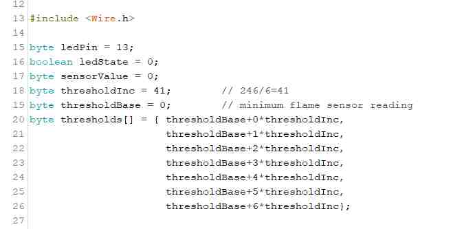
And here is the full code uploaded to Aaron's board:
#include <Wire.h>

byte ledPin = 13;
boolean ledState = 0;
byte sensorValue = 0;
byte thresholdInc = 41;        // max flame sensor reading = 246 --> 246/6=41
byte thresholdBase = 0;        // min flame sensor reading
byte thresholds[] = { thresholdBase+0*thresholdInc,
	thresholdBase+2*thresholdInc,
	thresholdBase+3*thresholdInc,
	thresholdBase+4*thresholdInc,
	thresholdBase+5*thresholdInc,
	thresholdBase+6*thresholdInc};

void setup() {
	Wire.begin(10);                // join i2c bus with address #8
	Wire.onReceive(receiveEvent); // register event
	Serial.begin(9600);           // start serial for output
	pinMode(ledPin, OUTPUT);
	digitalWrite(ledPin, ledState);
	pinMode (2, OUTPUT);
	pinMode (3, OUTPUT);
	pinMode (4, OUTPUT);
	pinMode (5, OUTPUT);
	pinMode (6, OUTPUT);
	pinMode (7, OUTPUT);
}

void loop() {
	delay(100);
}

// function that executes whenever data is received from master
// this function is registered as an event, see setup()
void receiveEvent(int howMany) {
	while(Wire.available()){
		sensorValue = Wire.read();
	}
	if (sensorValue > thresholds[0] && sensorValue <= thresholds[1]){
		digitalWrite (2, HIGH);
		digitalWrite (3, LOW);
		digitalWrite (4, LOW);
		digitalWrite (5, LOW);
		digitalWrite (6, LOW);
		digitalWrite (7, LOW);
	}
	if (sensorValue > thresholds[1] && sensorValue <= thresholds[2]){
		digitalWrite (2, HIGH);
		digitalWrite (3, HIGH);
		digitalWrite (4, LOW);
		digitalWrite (5, LOW);
		digitalWrite (6, LOW);
		digitalWrite (7, LOW);
	}
	if (sensorValue > thresholds[2] && sensorValue <= thresholds[3]){
		digitalWrite (2, HIGH);
		digitalWrite (3, HIGH);
		digitalWrite (4, HIGH);
		digitalWrite (5, LOW);
		digitalWrite (6, LOW);
		digitalWrite (7, LOW);
	}
	if (sensorValue > thresholds[3] && sensorValue <= thresholds[4]){
		digitalWrite (2, HIGH);
		digitalWrite (3, HIGH);
		digitalWrite (4, HIGH);
		digitalWrite (5, HIGH);
		digitalWrite (6, LOW);
		digitalWrite (7, LOW);
	}
	if (sensorValue > thresholds[4] && sensorValue <= thresholds[5]){
		digitalWrite (2, HIGH);
		digitalWrite (3, HIGH);
		digitalWrite (4, HIGH);
		digitalWrite (5, HIGH);
		digitalWrite (6, HIGH);
		digitalWrite (7, LOW);
	}
	if (sensorValue > thresholds[5] && sensorValue <= thresholds[6]){
		digitalWrite (2, HIGH);
		digitalWrite (3, HIGH);
		digitalWrite (4, HIGH);
		digitalWrite (5, HIGH);
		digitalWrite (6, HIGH);
		digitalWrite (7, HIGH);
	}
}
Here is also the code uploaded to the master Arduino Nano board, which is a combination from the examples master_reader and master_writer in the Wire library:
#include <Wire.h>

byte sensorValue = 0;

void setup() {
	Wire.begin();        // join i2c bus (address optional for master)
	Serial.begin(115200);  // start serial for output
}

void loop() {
	/*Wire.requestFrom(10, 6);    // request 6 bytes from slave device #10

	Serial.print("Node@10 answers: ");
	while (Wire.available()) { // slave may send less than requested
		char c = Wire.read(); // receive a byte as character
		Serial.print(c);         // print the character
	}

	delay(500);

	Serial.print("\t");
	Serial.print("\t");
	*/

	Wire.requestFrom(9, 1);    // request 1 byte from secondary device #9 (My ATtiny44 board)

	Serial.print("Node@09 answers: ");
	while (Wire.available()) { // slave may send less than requested
		sensorValue = Wire.read(); // receive a byte as character
		Serial.print(sensorValue);         // print the character
	}

	delay(50);

	Wire.beginTransmission(10); // transmit to device #10 (Aaron's LED board)
	Wire.write(sensorValue);              // sends one byte
	Wire.endTransmission();    // stop transmitting

	Serial.println();

	delay(50);
}
And here is the full network:
The codes work!