Group Assignment
Communication Between Networked Boards
Schematic
For the group assignment this week. We sent some I2C communication between Roland's project board and Aaron's Satshakit. We had an ATtiny44 running an analog Hall sensor, sending data back to a master on the I2C bus...and then that master sends a command to the Satshakit to ack as a bar graph depending on the output of the Hall sensor.
Setting Up the Circuit
Schematic
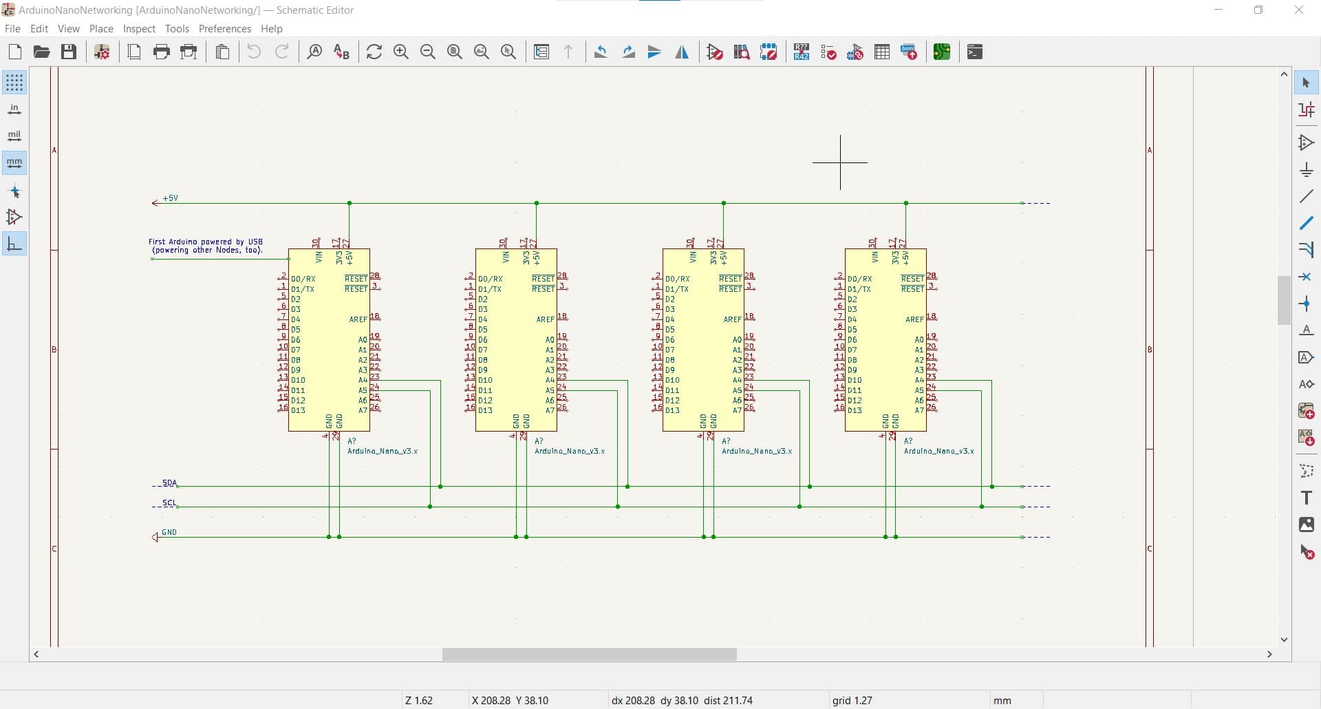
Here is the original schematic with four Arduino Nanos. The final circuit is the same, we only replaced two of the Nanos with the Satshakit and with Roland's ATtiny board that was controlling the Hall sensor.
What We Learned
We spent a couple hours playing with four Arduino Nano's and a breadboard communicating via an I2C bus. We started by connecting four Arduino Nano's together in a bus via their SDA and SCL pins using the I2C serial communication protocol. We installed the Wire library for the Arduino IDE and then used the pinout for the Arduino Nano and hooked everything up starting with the I2C bus. Then we iteratively changed the example codes from the Wire library making sure that they continued to function as intended with each change.
We learned that when using the Arduino as ISP to program the ATmega328P, you need to scroll down in the ArduinoISP code and uncomment the line to USE_OLD_STYLE_WIRING...and when we USE_OLD_STYLE_WIRING, we also have to tell the IDE what we have done. So in the tools menu, we had to change the processor to the old bootloader for the ATmega328P.
We also learned that the RX and TX LEDs on the Nano are not connected as they are on the Uno. Where they seem to be physically connected in the Uno, it seems to be a virtual connection in the Nano. We did some experimenting with this using some other LEDs and a couple resistors. More info is available if necessary.