Final Project
Small portalrobot for watering (farming)
After a long period of thinking about a final project idea and having multiple different ideas in week 1, I settled for something compleetly different: a sort of portal robot, that is able to water and observe a given field of plants. I have not yet decided on a final idea as to how this robot will eventually look and what amount of functions it has. For now im standing between a cubic design and a round but vertical design.
The idea comes from my workplace where a few of my colleagues have built a system like this before on a larger scale. I want to sort of replicate this on a smaller scale without using too much commercial parts. I know I would need some sort of soil measurement, aswell as temperature and humidity sensoric. In the later stages I would wish for the robot to be able to identify different plants and schedule the watering accordingly with the species. I will try to update this page here, when im finally able to get some time in to design this thing after my exams!
Update: Due to sickness and some personal reasons I am sadly majorly behind with this project at this point in time. I am however trying my best to catch up and do make this thing work (Atleat in the smalles workable prototype possible). Since this project will not stop after FabAcadamy, as I am going to try and write my masters thesis around this project, I will do my very best to catch up now. For now, my only Goal, is to be able to water the plants according to soil measurements. The later plans for this project include the integration of this project together with other farming robots using IOT applications and the function to reorder the planting pots automatically, by grabbing them with the tool and setting them back down in another space. For now however, the first thing I want to be able to do is moving and building this thing.
Different Work packages to be done:
- First rough sketch of my idea
- Making a CAD model of the whole contraption
- Which materials am I going to use and need?
- What sensors do I need for Input?
- What kind of Output do I want?
- What electronics do I need
- Which problems do I need to fix?
First Rough Sketches
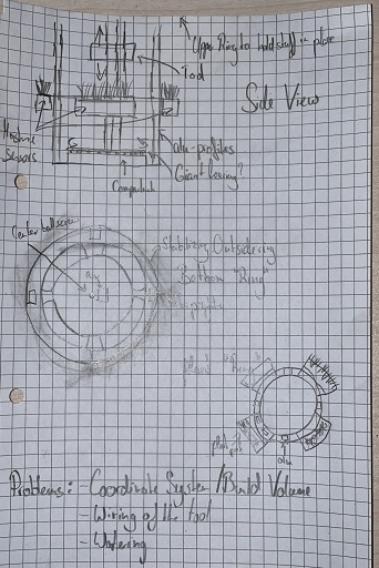
Making a CAD Model
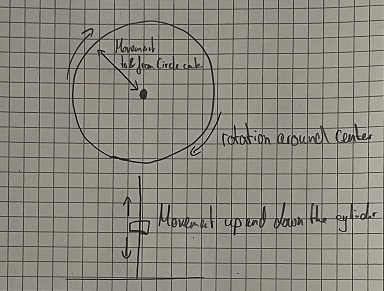
For the CAD Model, I sat down and had the Idea of a circular plantable cylinder. This cylinder would have some layers, where plants can be inserted into "slots". These layers would look something like rings, where the planting pots could be hanging on the outside of said rings. On top of a Base in the bottom middle of the cylinder (Where the electronics would be positioned), a platform would sit that would be able to rotate around its center. On top of this, a contraption would be placed that would allow a toolhead to move up and down inside the cylinder. The tool can then extend from the center of the circle to the outside. This would mean, that the rotation of the tool, paired with the position of the tool between the inside and outside of the circle, would make up the X/Y direction. The Z direction would be the toolhead moving up and down inside the cylinder. My first CAD Model looks like this:
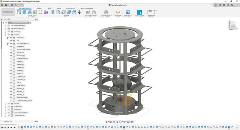
As you can see, the tool in the middle will be able to move up and down. The planting inserts on the outside still have to be changed in order to fit commercially available planting pots for balconies. After having a talk with my instructor, it became clear, that this would be one of the items, that are better bought than made myself. I also already have cutouts for the tool to get into, in Order to accomplish the grabbing and relocating in later stages. For now however only the watering is interseting for me. Also I really need to rework some things here, so i will update this CAD very soon. This CAD also does not answer many of the open questions. So I am trying to answer them next.
Material
For the Base and the top, I thought I could safely go with 12mm or 16mm wood. For the planting rings, I want to go with machined aluminum, as I am afraid, that the weight of the plants with dirt would be too much for the wood to hold. Apart from Wood and aluminum for the base structure, I would need aluminum profiles to make some sort of skeleton for the planting rings to attach to with the help of aluminum angles for connecting profiles. I will update this section with a BOM later on! BOM: TBD
Sensors/Input
As an input and to determine which plants need watering, I want to use Soil Moisture sensors. Since I am going to use multiple sensors, and this structure as a whole is kind of extendable in the z direction, I would love to use I2C to connect all the moisture sensors. This would mean that all of the sensors could be connected to a single bus, which would eliminate the pin shortage when connecting them all indicidually to pins on a control Board. The problem is finding a Soil Moisture sensor with an I2C Adress that can be changed freely. Something like this is able to change the I2C adress between four individual adresses, which would mean, that I would need one control Board for each planting ring. As for measuring the soil moisture, I already did that in Input week, so you can read about it here. If the time allows it, a general temperature and humidity sensor would also be nice. For temperature and humidity I also already used a sensor in Input devices Week.
Output
There are two general Output I want to achieve. On one hand I clearly want to move some stepper motors in order to achieve movement and on the other hand I want to have a small screen, that displays the most important information to the User. For the motors, I already work on this stuff sice machine building week. I designed and build my own Ardunio shield with a AtMega328p already on Board. While the first revision was sadly unusable to a degree, which you can read up about on my documentation of machine building week. For now I was able to move motors with it using GRBL. I still have to talk with my instructor on how to change GRBL in order to use it with this setup. In case GRBL is unable to recognize this Build volume, which I am almost certain it will not, I had the Idea of creating a central "computing station", that would be taking the moisture sensor values, the current position of the tool and calculate the next best possible plant to go to to water it. This Board would then generate GCode, which it would send to the Driver Board, which will then move the stepper motors accordingly.
For driving the small display, I already made some experience with a small OLED screen in network and communications week, which you can read up about here.
Electronics components
For this project I would need many componenets, some of which I already talked about in the two previous passages. I will list a preliminary list of what I will need here:
- Motor Driver Board (see here)
- Soil Moisture Sensors (see here and here)
- Small Board to collect the I2C Data for each plant ring
- Maybe Temp/Humidity Sensors
- Power Supply 12V
- Power Supply 5V
- Stepper Motors
- Servo for controlling the water flow
- Central Control Board (Reading Soil sensor, position of tool, writing GCode and to OLED screen)
This list will be further Updated, the more i get to finishing this thing of course.
Further open problems
Water
For now the solution for this problem I had in mind, was using the Gravity to my advantage. My idea is a circular water tank on top of the contraption and a valve on the toolhead thats being opened by a servo. In this case the gravity would do the watering, and the amount of water would be controlled by the time the valve is open. The other Idea would be a water tank at the bottom with a pump attached. The problem with this approach is, that then I would have to worry about the water line, because it would need rotate with the toolhead. So for the moment I am mainly leaning towards the small water tank at the top. Because of its size you would need to refill it more often, but other than that and maybe the weight as a constraint, I do not see other downsides.
Connecting Wires through rotational disk
A simillar problem to the one above, is the wirking of the toolhead and the stepper motor for the z movement and the inside/outside of the circle movement. For now my only solution to this problem, is to restrict the rotation of the device. Instead of beiong able to freely rotate 360 degrees, the idea is to limit the rotational angle between 180 and -180 degrees. This would mean, that the cables would need to be a little bit longer, but are able to move with the rotation. The downside would be the worst case szenario would be that the tool would need to move from -180 degree to 179 degree. Instead of stepping over, the code would (hopefully) generate a GCode that would move the tool the other way around. But, the upside is, that this machine will water plants and time is not as critical as in other applications, so longer tool paths is no real problem, as long as the tool gets to its target in the end.
!!!Update!!!
After weeks of building and troubleshooting and problems to be solved, the day of the presentation finally came. From here on I will show you the final design decisions, what was done and what problems occured during the last few weeks. For the beginning, I would like to list all of the materials I used for this project. This list will maybe not complete, as there are many components I might miss, but I try my best to give you a complete look at what this machine is made of:
- Starting with Wood, I used the following:
- 2.5mx1.25m of 18mm thick black coated plywood for the planting rings and the stop for the X axis
- Approximately 2.5m x 1.25m of 25mm thick MDF for the Base and the top Ring (Reused the old Sacrificial Layer of our CNC at the Lab for this!)
- Approximately 2m x 1.25m of 15mm thick normal plywood for the toolhead, the round base, the gear ring and the top stop plate for the rotating center
- Eight 2m long 30mm x 30mm aluminum profiles for the outer structure and the rotating center (four for each)
- Approximately 60 angle brackets to connect the wooden structures to the aluminum profiles
- Enough M4, M5 and M6 screws with washers and nuts to connect everything
- Electronics:
- My Motor Driver GRBL Board
- My SAMD21 Main Controll Board
- 3 Attiny1614 based Boards collecting data from the I2C Sensors (One for each Ring)
- (Soon to be) 12 I2C Soil Moisture Sensors by Adafruit (Link)
- A Nema23 Stepper Motor with a brake for the Y axis(Link)
- A normal Nema23 Stepper Motor for the X Axis
- A normal Nema17 Motor for the Z-Axis
- A solenoid valve for allowing waterflow
- Two small Boards with a Mosfet allowing to actuate the Solenoid valve and the Brake respectively
- For now a Bench Lab Power supply , supplying 12V and 10 Amps to the system (12V 41A PSU is ordered already!)
- Two individual Voltage step up converters, going to 24V each, for each of the two Nema23 Motors
- A Polulu SilentStepStick, driving the Z axis Nema17 Motor
- A Leadshine DM542EU Stepper Motor Driver for the X-Axis Nema23
- A Leadshine DM556EU Stepper Motor Driver for the Y-Axis Nema23
- Cables with different Gauges and Lengths, custom made and sometimes outfitted with XT-60 / XT-90 plugs for easier disasemble)
- Three endstops, one for each axis, allowing a homing cycle
- A 2m long Ballscrew to move the Toolhead vertically inside the machine (Link)
- A coupler, connecting the Ballscrew to the Motor
- A coupler connecting the X-Axis Motor to a custom 3D-printed Gear, interfacing with the Gear Ring in the Base
- A approximately 30cm long acrylic Rod, that was cut to allow cables to pass through, resigning inside the base
- Two NTN 4T-LM102949/LM102910 Bearings connecting both ends of the acrylic rod within the base (Link)
- Approximately 80 12mm steel balls connecting the Gear Ring with the Bottom of the Rotating Platform, acting as a ǵiant self made Ball Bearing
- 12planting pots, bought from the local garden center (Link)
- Two 110cm HIWIN linear Rails HGR20R (Link)
- Four HIWIN Linear Rail Carts HGH20CAZ0H (Link)
As i said above, this list might not contain everything as it was so much that I needed to use over the past couple of weeks. I will do my best to update this List however. Going on, I want to go thorugh every discipline of the last weeks and show of, what I did myself in the final project using this specific discipline:
Computer-Aided Design
-
Base Structure (MDF Top and Bottom)
To structurally connect the planting rings together, I wanted to utilize heavy and quite big pieces of wood at the top and at the bottom of the interfacing aluminum profiles to create some sense of structural stability, especially having the planting pots and their individual weight in Mind. To keep it simple, I just made two rounded shapes and for the bottom distinguished between the outer perimeter with the intefacing aluminum profiles and the center where the rounded base should later resign.

Drawing of the bottom base plate 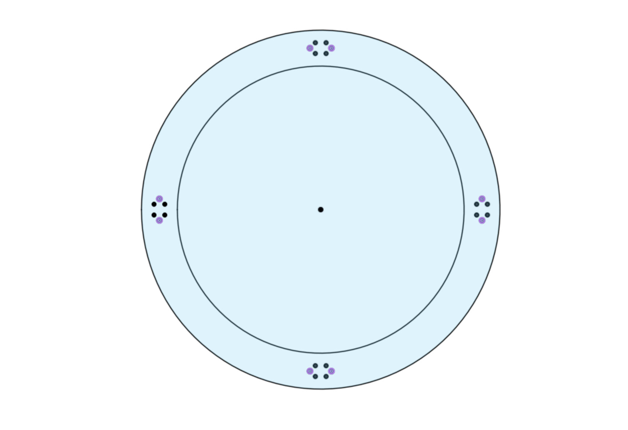
Drawing of the top plate -
Rounded Base and Inner Gear (15mm Plywood)
At first, the plan was to use a huge steel pipe with the given diameter of the base, simply putting it in place. Since that was not at all feasible timewise, since the pipe would have to be made to order, I instead opted for kerfing a straight piece of Wood into some kind of barrel and through time, glue and a little bit of force make it sit inside the bottom base. To calculate the spacing and cuts for the milling, I used this calculator and created the following drawing:
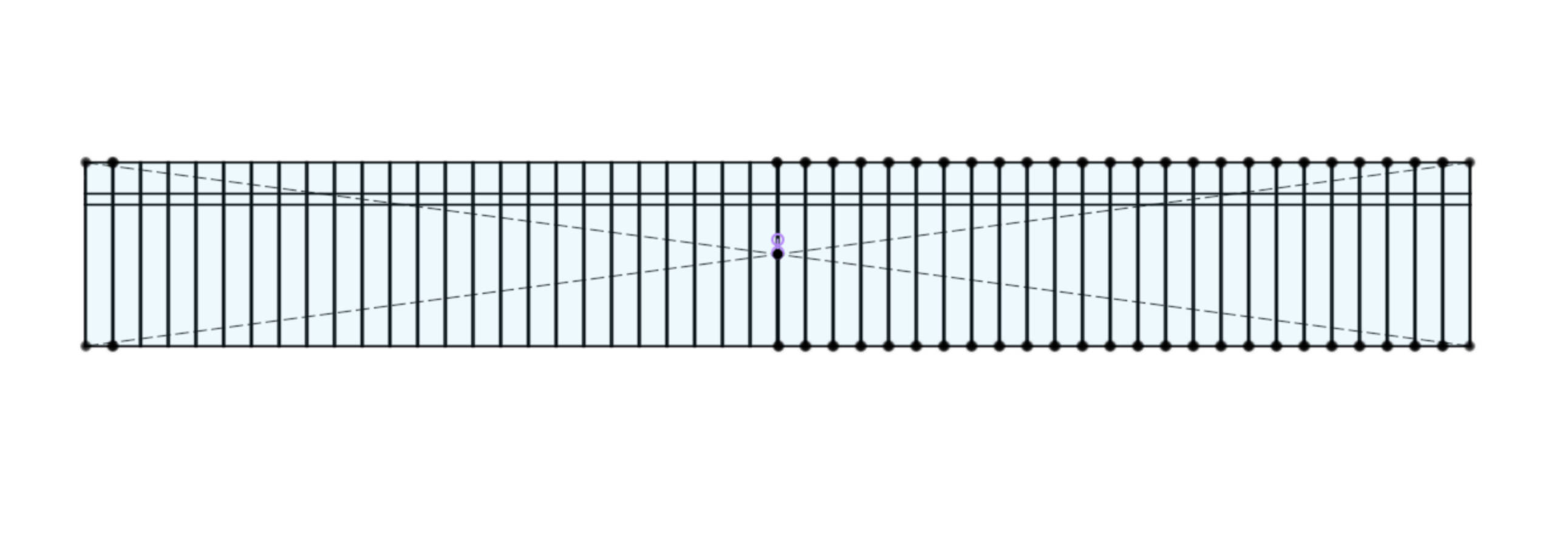
The drawing of the straightened out rounded base As you can see in the drawing above, I not only had lines for cutting the pockets for kerfing, but also had envisioned a pocket for the gear insert I had planned. The pocket would just accept the gear insert while being rounded up into a barrel, making the connection between the base and the gear insert evry stable and strong. The drawing for the gear insert, can be found below:
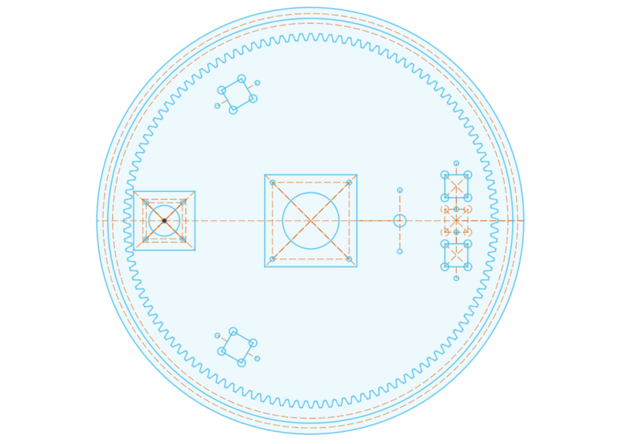
The drawing of the Gear insert ring (doubles as drawing for the moveable base and top) -
Central Bottom and Top (15mm Plywood)
While the top was pretty much straight forward, as it only is used as a receptable for the four inner aluminum profiles and also has a hole cut out for the ball screw, the bottom was quite a bit more challenging. First of all, the bottom has to be milled with the bottom side of it facing upwards on the CNC mill, so that the groove for the steel balls can be milled together with all the pockets and drill holes. I also had to decide on final places for the motors on the bottom plate when designing it, as the motor for the X-Axis and the motor of the Y-Axis are both present ont this plate. Also the center cutout had to be of a specific size, since I wanted to use the NTN bearings that are mentioned in the List of Materials above. With all of this in Mind, this was the final drawing of the top bottom and top pieces:
The drawing for the moveable base and top (doubles as drawing for gear insert) -
Planting Rings (18mm Coated Plywood)
The planting Rings were really straight formward design wise. I just needed a Ring wide enough to allow the planting pots to be inserted easily without much wobbling. For this, I went ahead and searched for ülanting pots in a size I thought would fit pretty good and found the pots listend above in the list of materials. After coming up with a first sketch and trying to lay it out properly on the coated plywood, I noticed that I would have too much scrap left over and cannot even cut all three rings with this one sheet of plywood, so I opted to cut each ring in half and just mill six of these halves.
The drawing for the moveable base and top (doubles as drawing for gear insert) -
Toolhead (15mm Plywood)
For the toolhead, I quickly threw together a design, which would allow an additional axis, as well as using the carts on the linear railings as a mounting point. I also wanted to make the toolhead as a pressfit kit. In the end, the cad model of the toolhead can be seen here:
Model of the Toolhead
Computer-Controlled Cutting
-
Plate for Y- and Z-Endstop
Since we needed two mounting plates for the Endstops for Y and Z to be out of thin material, I just quickly made them with the lasercutter using the known dimensions between the the aluminumprofiles that connect to the toolhead via the linear railings and for Z with the known dimensions of the toolhead itself.
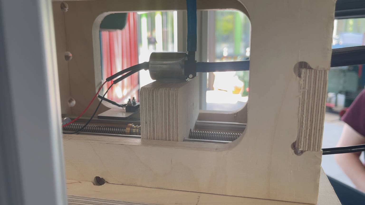
Image of mounted Y axis Endstop mounting plate
Image of mounted Z axis Endstop (Behind the Solenoid Valve)
Electronics Design and Production
-
GRBL Stepper Motor Driver Board
Selfmade prototype of the GRBL Board This Board is already explained to a greater extend on the page for my Machine building week. To make a short summary of what this Board is capable of:
- Arduino Uno and CNC Shield in one Board
- AtMega328p based
- Support for three axes (Three slots for Polulu SilentStepSticks)
- Support for up to six endstops (Two per axis)
- 12V Intake for Motor current, step down to 5V on board for MCU and logic
- Serial Communication port
- SPI interface to burn bootloader through an Arduino Uno
- All GRBL out- and inputs are accessible (like coolant or GRBL reset)
- Board milled from both sides
Since I already did two prototypes of this Board and had many problems getting it to work due to problems with the vias connecting the two sides of the Board properly and most importantly because I really wanted to test it out, I ordered the Board for the final project from JLCPCB, where I just uploaded all the needed Gerber files from my KiCAD project. For this I had to change some things minimally, like the Text I wanted to have on the Board. Instead of using the Edge Cuts Layer, I switched to the Silkscreen layer. Upon uploading the files, I opted for the lead free option and although taking more time, I opted for the black PCB coating instead of the normal green one. The whole process of ordering the Board is really easy and quick once you know what each setting does. The time between ordering the Board up until production was finished was very minimal, the longest time frame was the actual shipping, which was also the most expensive part of the whole order, coming in at roughly double the cost of all the items within the order.
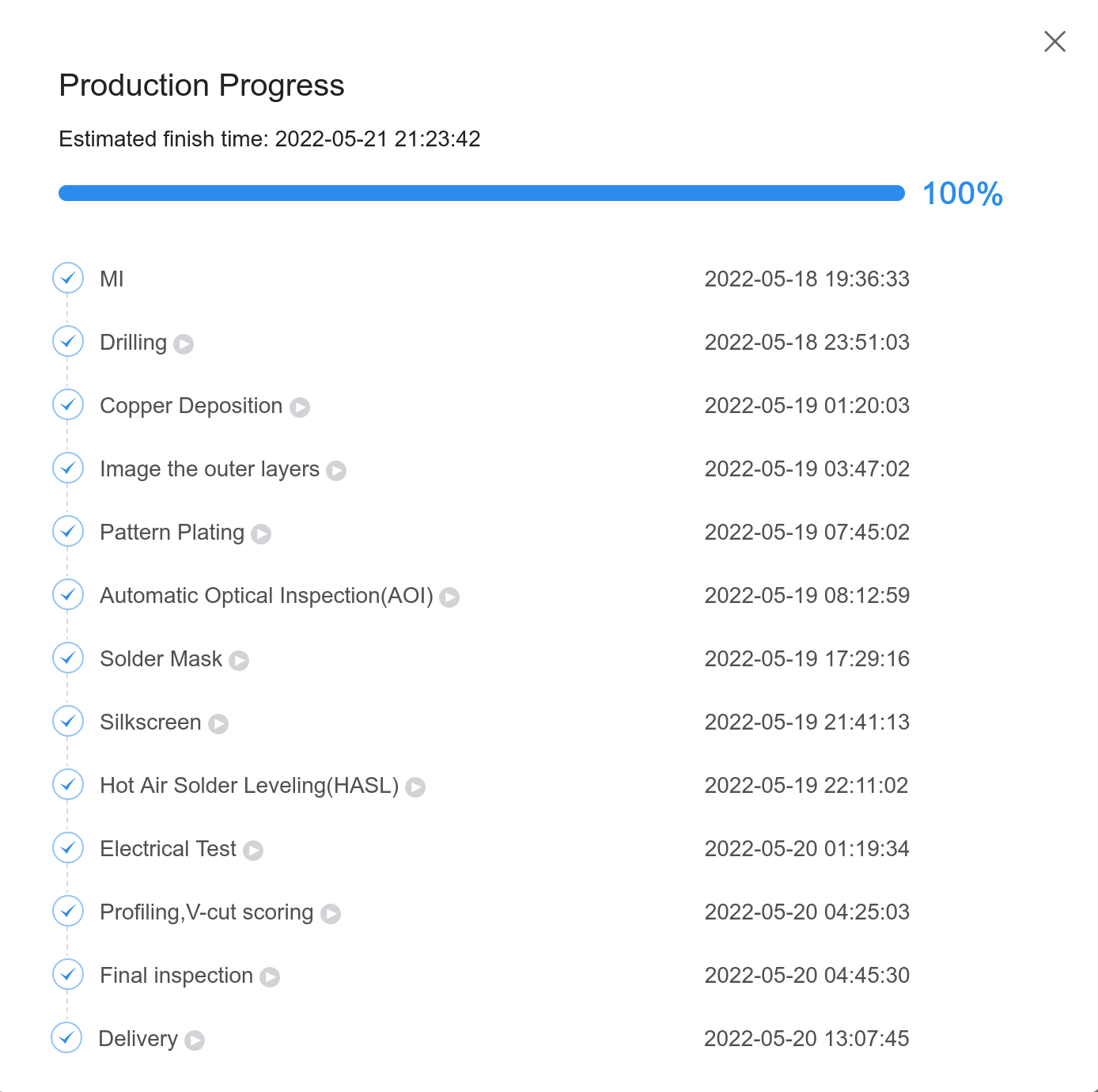
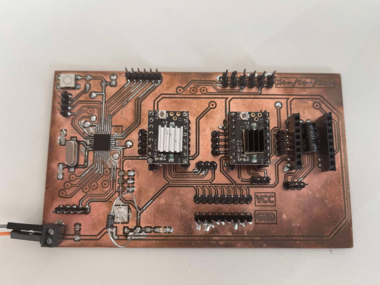
The process at JLCPCB from the order being placed up until the shippment of the delivery from their facility As you can see, the whole process, did not even take three working days. Had i picked the green silkscreen option, the whole process would have been even faster. Once the PCBs were dispatched, I had to wait a little bit over a week for them to arrive at my place. I was really really excited when they arrived. My first self designed PCB with industrial quality. Really cool! And I was certainly not disapointed. The quality was really astonishing. Here are pictures of the front and the back of the Board:
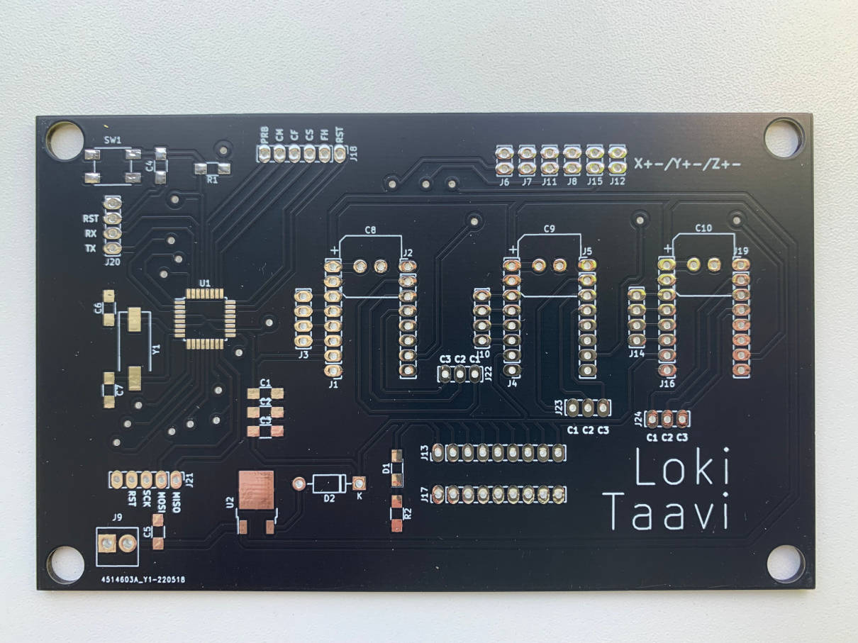
Front of the GRBL Board 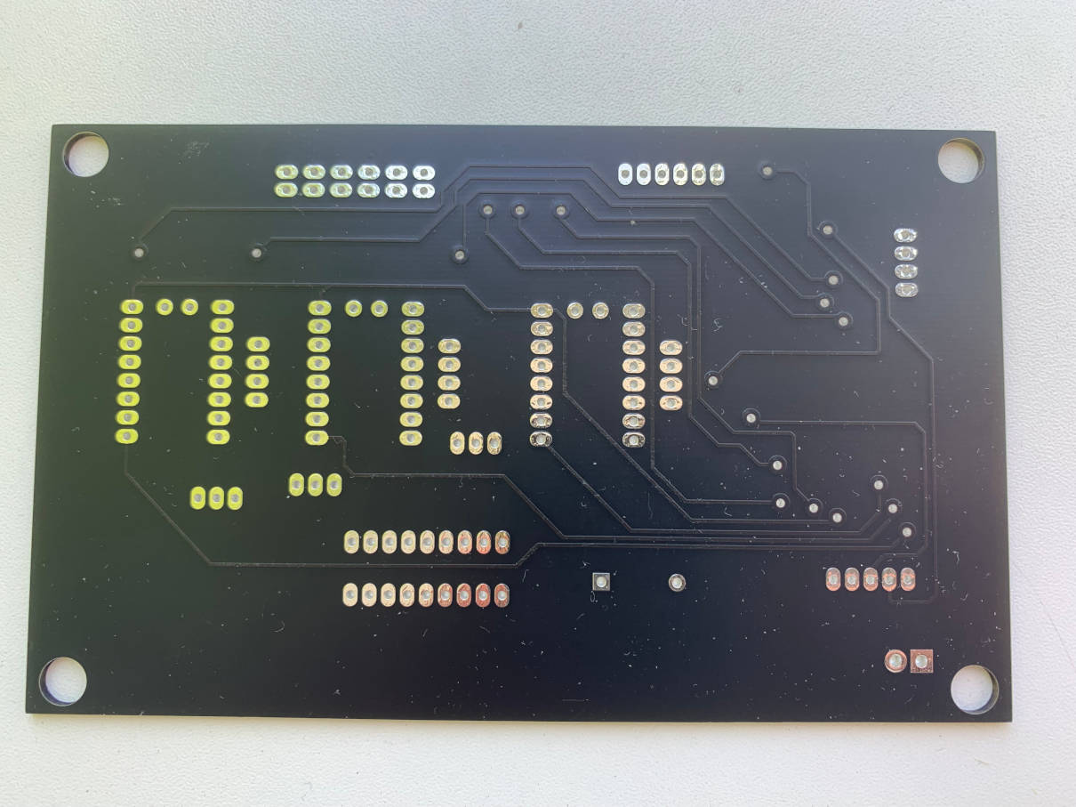
Back of the GRBL Board I also really have to say, that soldering was so much simpler. I did not have the fear of briding to my Ground layer all the time while soldering, which was really nice. The pre tinned pads also accepted the solder more than well, making the whole process of stuffing this Board very simple and fast. Here is the final result after soldering:
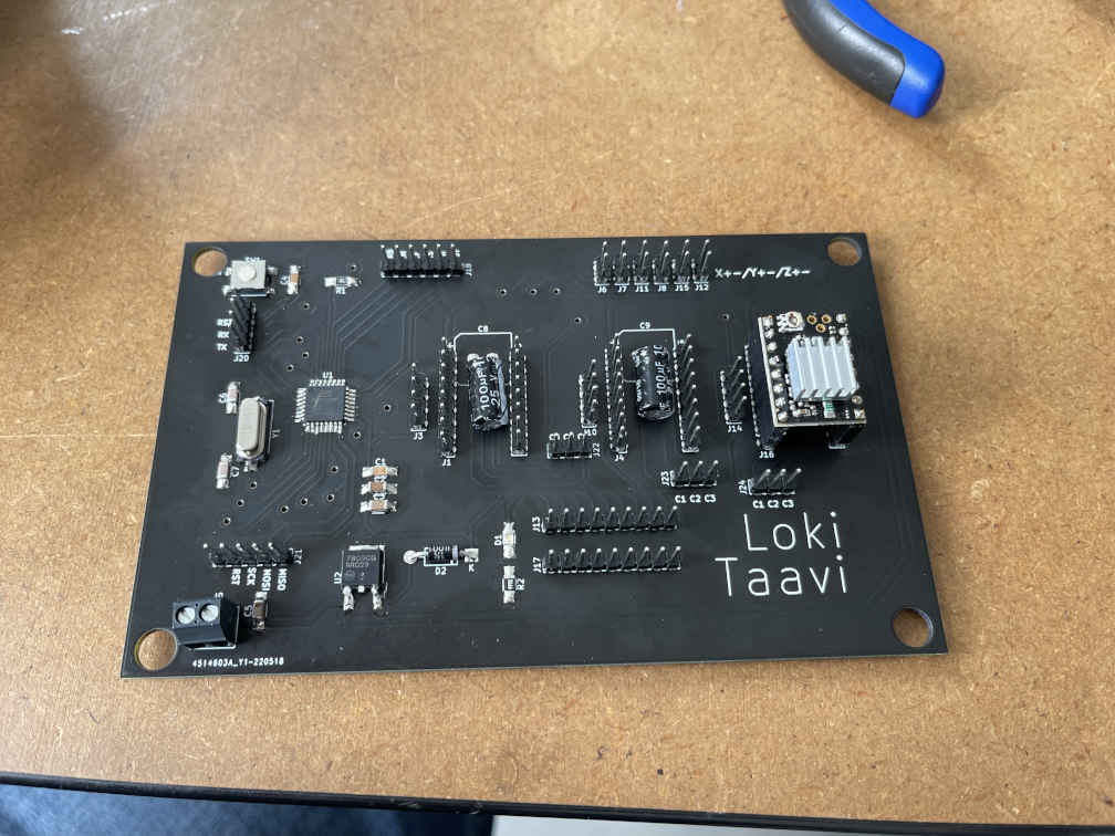
Front of the GRBL Board (soldered) 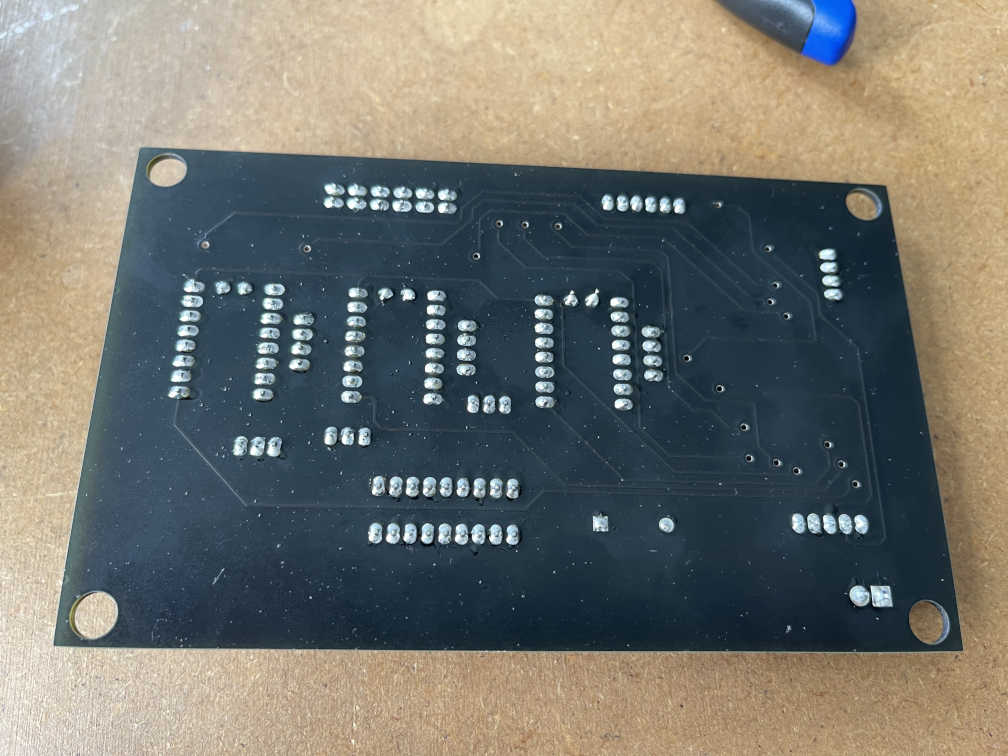
Back of the GRBL Board (soldered) -
SAMD21E17A Main Control Board
The idea behind this Board is, to use it as a central computing unit. Its task will be to take in all of the data gathered through the soil sensors spradically (Soil is not drying out within seconds, so it makes next to no sense, sensing the soil every second for changes), and turn this information into a toolpath, respresented with GCode. Since I will be using a few libraries, I opted for the SAMD21E17A, as it comes with 128kb flash storage, which is plenty for what I am going to do. Apart from the MCU itself, the Board comes with a USB port for programming, a voltage regulator, that steps down from 5V to 3.3V, which the SAMD21 runs on. It also features a normal 5V pin input, that goes into the Vreg to be turned to 3.3V. On top of that, it features a JTAG compatible pin configuration to burn the Bootloader the first time using EDBG and a JTAG programmer, as I already did for the SAMD21E17A in Embedded programming week. On top of that, it features two seperate serial communication ports, one for GRBL and the other one to later on in the products cycle being able to use an oled screen or something similar easily. Last but not least, it also features an I2C Port, for reading out the sensor data. All other open pins, that were easily routable, went to open pins, to be used later for whatever reasons. The design of the Board is relatively straight forward. Like all of my Boards, I used a ground flow layer instead of routing a seperate Ground line. After a bit of shifting components around and routing, this was the final design for this Board:
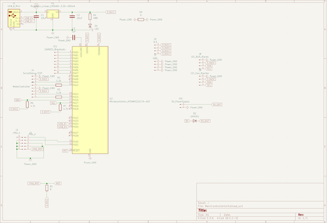
Kicad Schematic for the SAMD21E17A Main Control Board 
Kicad PCB view for the SAMD21E17A Main Control Board Soldering this board also was pretty much straight forward, and this was the final product after milling and stuffing:
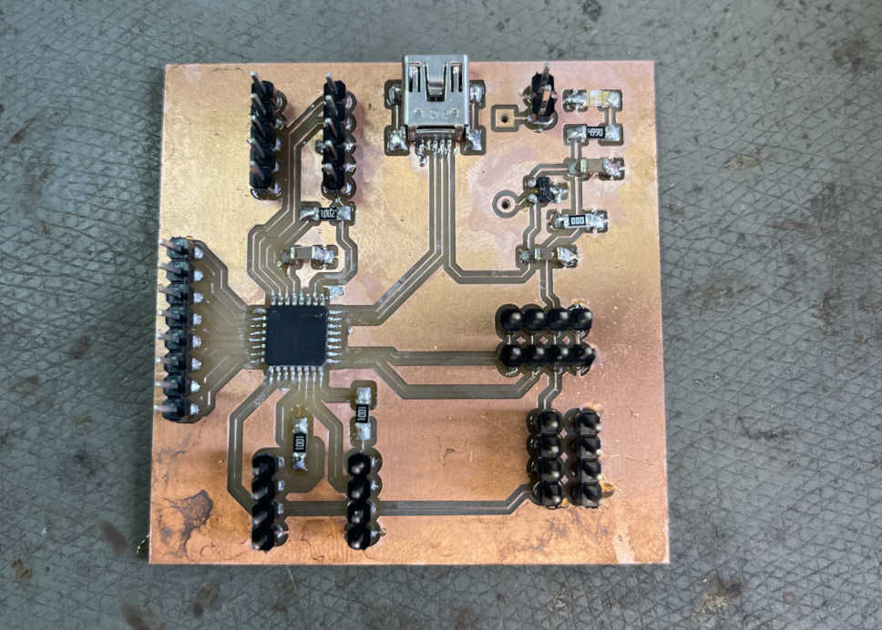
The finished SAMD21E17A Main Control Board (just the diode missing) -
Attiny1614 based I2C Collector (Maybe unused)
Since I early on figured, that I wanted to use the Adafruit I2C Soil Sensors, I already knew, that their I2C adress range can only be within four adresses. With 12 planting pots, that can be a problem. This is why I wanted to add "collection Boards" that collect the data from each level and then send the levels complete data to the main control unit. This is why I also settled on the SAMD21 above, since it sports a wide range of sercom ports, which would have allowed me to operate one port per level. I made these Boards early on and later on found a different solution, so for now, the Attiny1614 Boards are just sending through the I2C and power to each level without really utilizing the Attiny1614. I still opted for the Boards to stay this way, since I later maybe want to add temerature or light sensors to each leven, which can be read through these Boards then. Until then they are currently not used in their full capacity however.
Back to the Boards themselves. They have the following functionality:
- An Attiny1614 MCU
- Four I2C and Power ports for the four I2C Soil Sensors per level
- One pair of power and I2C coming in from the bottom
- One pair of power and I2C going out through the top
- A serial communication port for programming and maybe other sensors later on
As with the Main Control Board, the design here is pretty much straight forward and the only problem I had (one again!) was to find a way to let the Ground layer flow everywhere were it was needed. After having done so, this is the final product for these three Boards:
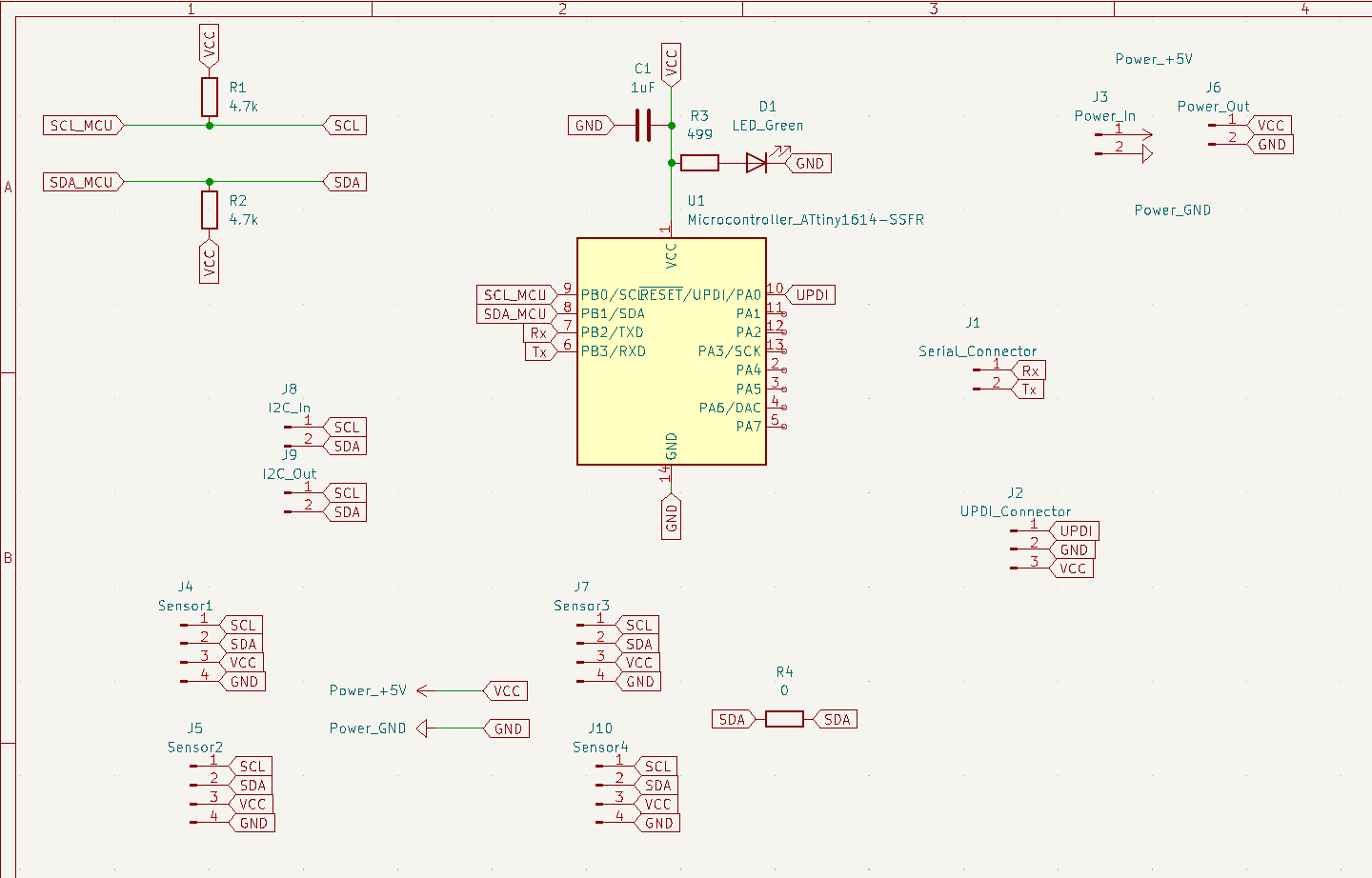
Kicad Schematic for the Attiny1614 Boards 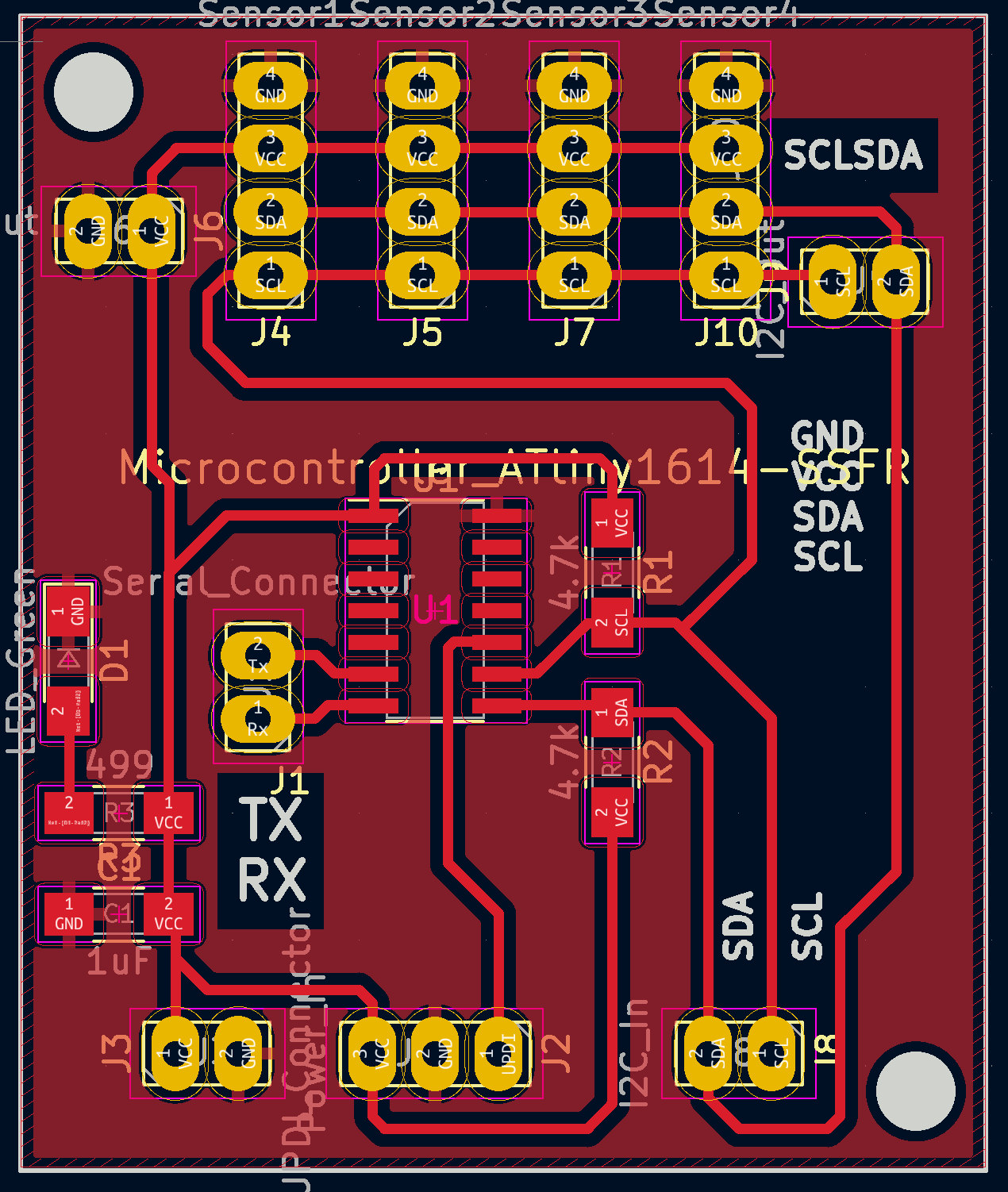
Kicad PCB view for the Attiny1614 Boards 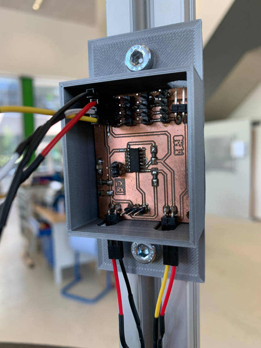
Image of the final Attiny1614 Board already in use -
Small Mosfet Breakout Boards for Solenoid and Brake
These are basically just two breakouts for a Mosfet, making it possible to actuate the 12V Solenoid or the 12V brake of the Y-Axis motor:
Mosfet Breakout
3D (scanning and) printing
-
Gear to interface X-Axis motor with the Gear insert of the base
As with the Wooden Gear insert, I used Fusion360s own Gear creation script. In comparison to the wooden gear insert, I changed the number of teeth to one fifth of the number of teeth on the wooden gear. Afterwards I just extruded the Gear by the thickness of the wooden gear and created a rod to interface the gear with the stepper motor, which I then joined with the gear. For this part I used PETG because of its sturdier nature. At first it was even planned to just make this gear as a proof of concept and later make the gear out of sturdier material or even cast it. It worked so well thought, that at least for now, I am still going to use it.
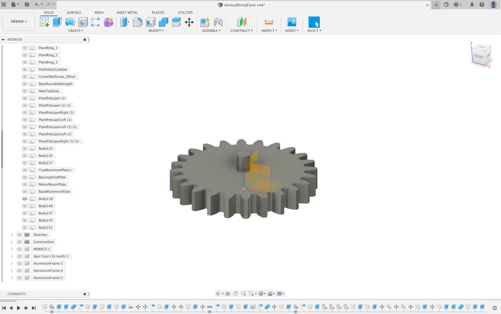
Model of the 3D printed Gear -
Housing for Attiny1614 Boards
To be able to mount the Boards that supply the I2C and power lines to the sensors to the aluminum profiles, I went ahead and designed a simple case for the Boards. The case should offer holes at the bottom and the top as well as inside the lid to reach all the pins. It also has to feature two mounting holes,so that it can easily be mounted to the aluminum framing with just a nut, a washer and a screw. The design itself was quickly made, as I had exact dimensions of the Boards from KiCad. The only thing that was kind of difficult was to make the lid fit onto the base properly, with the deviations of 3D-printing in mind. After two test prints, I had dialed in the settings well enough to have the lids stay on the base. I printed the cases in silver PLA to make them kind of fuse into the aluminum frames.
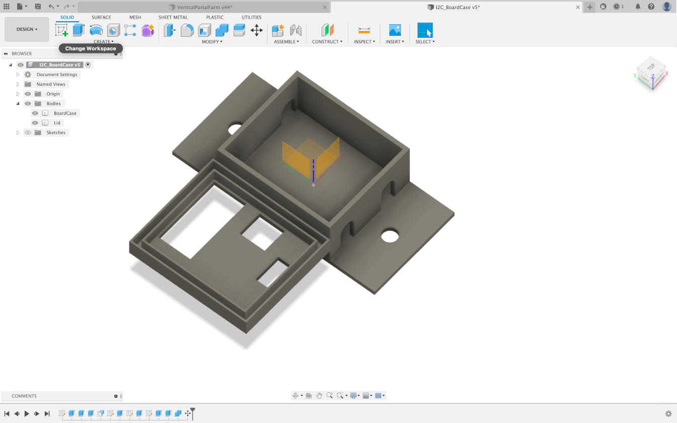
Model of the 3D printed case -
Caps for HIWIN linear Railings
We noticed pretty late, that the place we bought the linear rails from does not deliver them with the signature green caps for the mounting holes. This is where we just 3D printed them after taking a few measurements from a single realcap we got, due to ordering a very short version of the rail from another vendor. The added Bonus here, is that the design was quite simple and a stack of almost 30 of these little guys could be printed in just under two hours! A further Bonus is, that we could choose the colouring, and of course we chose silver, to fit into the aluminum framing and rail color scheme, they are almost invisible from afar!
Selfmade caps for the HIWIN rails -
Motor Mount for the Y-Axis
This follows almost the same design as my motor mount for the X axis of the ISS tracker from Machine Building Week and just (supposedly) follows the size of the actual Y Axis Motor. Due to my mistake I suppose it came out to large and a little bit too narrow however, hence why I need to redesign it still.
3D printed Mount for the Y-Axis motor
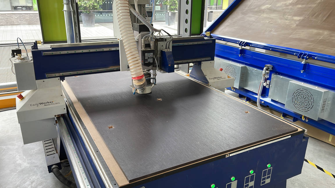
Computer Controlled Machining
-
Base Structure (MDF Top and Bottom)
This was by far the most straight forward process of all of the milling I had to do during this project. For the Base and the top I chose 25mm thick MDF in the form of the old sacrificial layer of our CNC in the FabLab. It was so simple because it was just flat. No warping, no problems with the stock sticking to the machine due to the absurd weight of the old sacrificial layer. For this specific part, I went ahead and used the Fusion 360 CAM processor. I used the drill function for the holes where the aluminum angles where going to connect. Then I used the pocket function for the cutouts of the aluminum profiles. One thing I could have definetly doen better retrospectively, was to enlarge the pockets for the aluminum profiles by .5mm or so, to make the profiles slide into place easier. As it stands now, I had to file quite a bit with the other CNC milled parts to get the parts onto the aluminum profiles. the rest of the cuts of the top and bottom piece were done with the 2D Contour function of the Fusion CAM processor. for this milling process I used the same tool, I used in Make something Big week, the 6mm one flute tool. The only change that occured, is that we went with a 6mm one flute tool with a slightly longer flute length, as the stock was thicker then in Make something big week. The process of cutting the pieces was the same across all elements I needed:
- Turn on Mains power
- Turn on acompanying PC
- Home CNC machine
- Put stock onto CNC mill
- Jog machine to desired X/Y position and set zero
- Let machine grab wanted tool
- If not done once before, let machine measure tool length
- Use Probe to measure stock thickness
- Load cnc file made by Fusion360
- Activate Vacuum bed
- Activate Air suction
- Put on protective gear (Goggles and ear protection)
- Start milling process with one hand on F4 for stopping, and the other hand on the Estop for cutting of the machine entirely
- After cutting, move toolhead out of the way
- Use a chisel and a hammer to get rid of the bridges for the contour cuts
- Take of machined parts and clean them (sanding)
- Take of stock if not needed anymore
Each and every milling process used this process described above. For the milling process of the Base I even captured a timeplapse:
Timelapse of the milling process of the Base of the machine 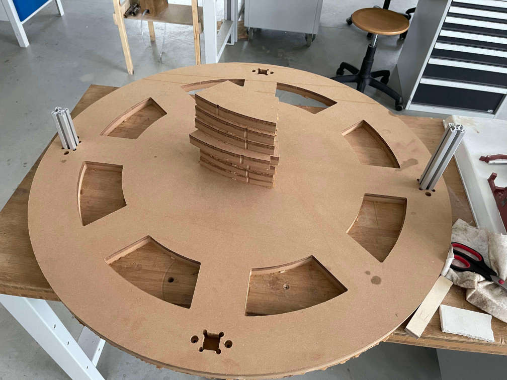
Finished Base -
Rounded Base and Inner Gear (15mm Plywood)
For the rounded base, as well as for the gear insert, Ahmed suggested to me to use a DXF file with differnet layers and using the CNCs own CAM processor. Mainly because we then could precut some of the small grooves with a bigger bit, so that we then easily cut cut in the same center with the smaller bit The problem was, that our 2mm CNC mill bit was quite short, so we premilled the grooves to a certain depth with a much longer 3mm bit. We also opted for the internal CAM processor and a dxf file to simply cut the Groove for the steel balls. For this we used a 6mm radius router bit. We measured the bits head size and simply went in with the router bit a little bit shorter then the bits height. The same we did later on for the rotating base plate. This resulted in a very beautifully machined groove for the steel balls, which mnade me very happy! Below I have Images of the CNC process for the Gear insert, the dxf settings on the CAM processor and the CNC process for the rounded base.
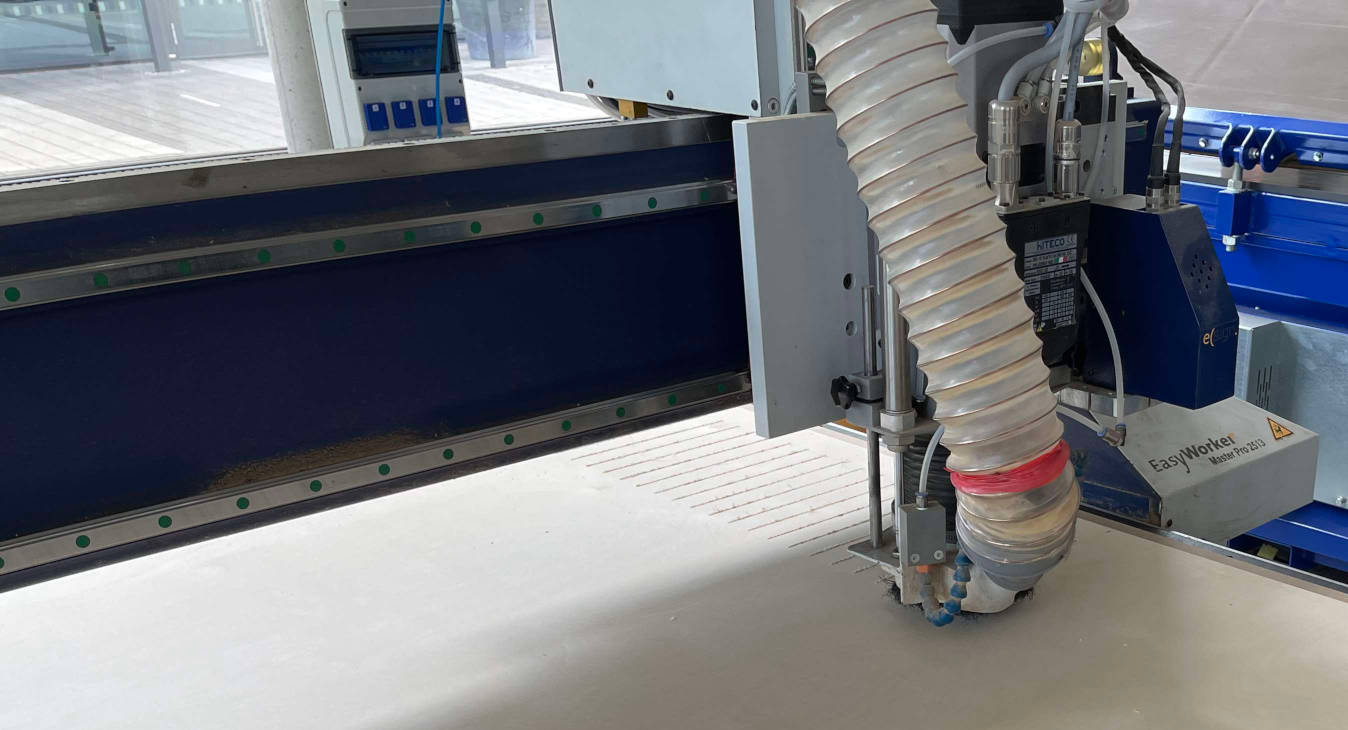
In process milling for the grooves of the straightened out round base 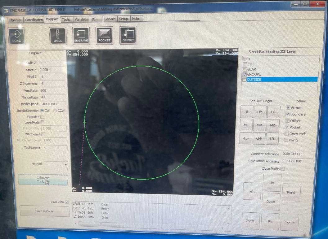
The cam settings for the groove of the gear insert specifically 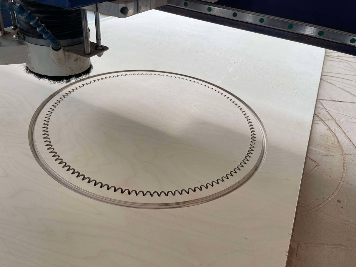
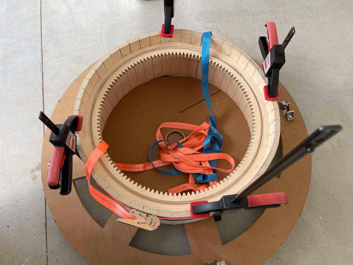
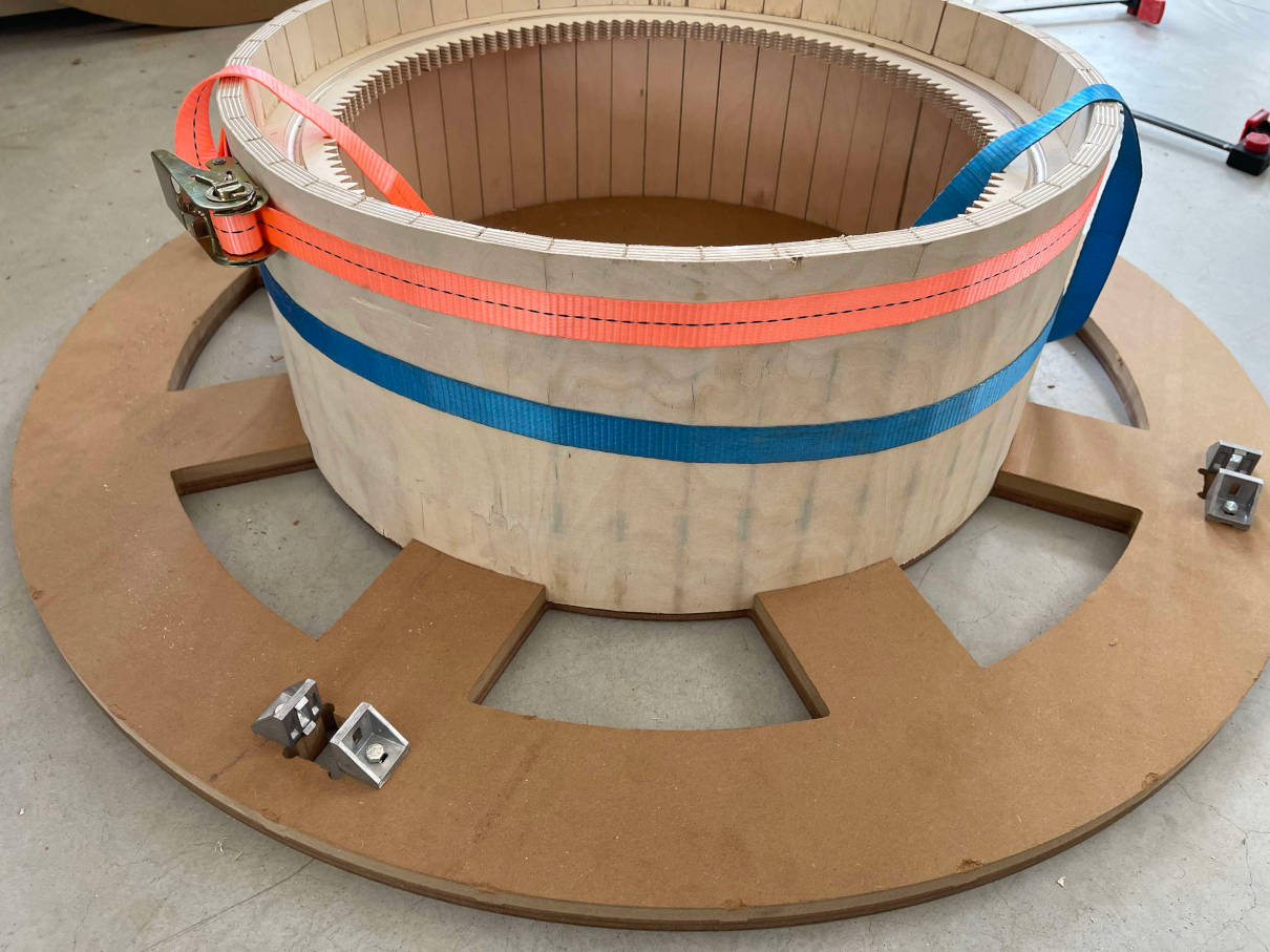
Milling process for the Gear insert with the groove already done! The next part, I was really afraid of. To start the process of bending the CNC milled piece of straight plywood into the rounded shape, we used warm to hot water and a piece of leftover stock from the base milling. With a huge amount of clamps and water we tried to force the piece of wood into place gently and leave it inside the "mold" for a day or two:
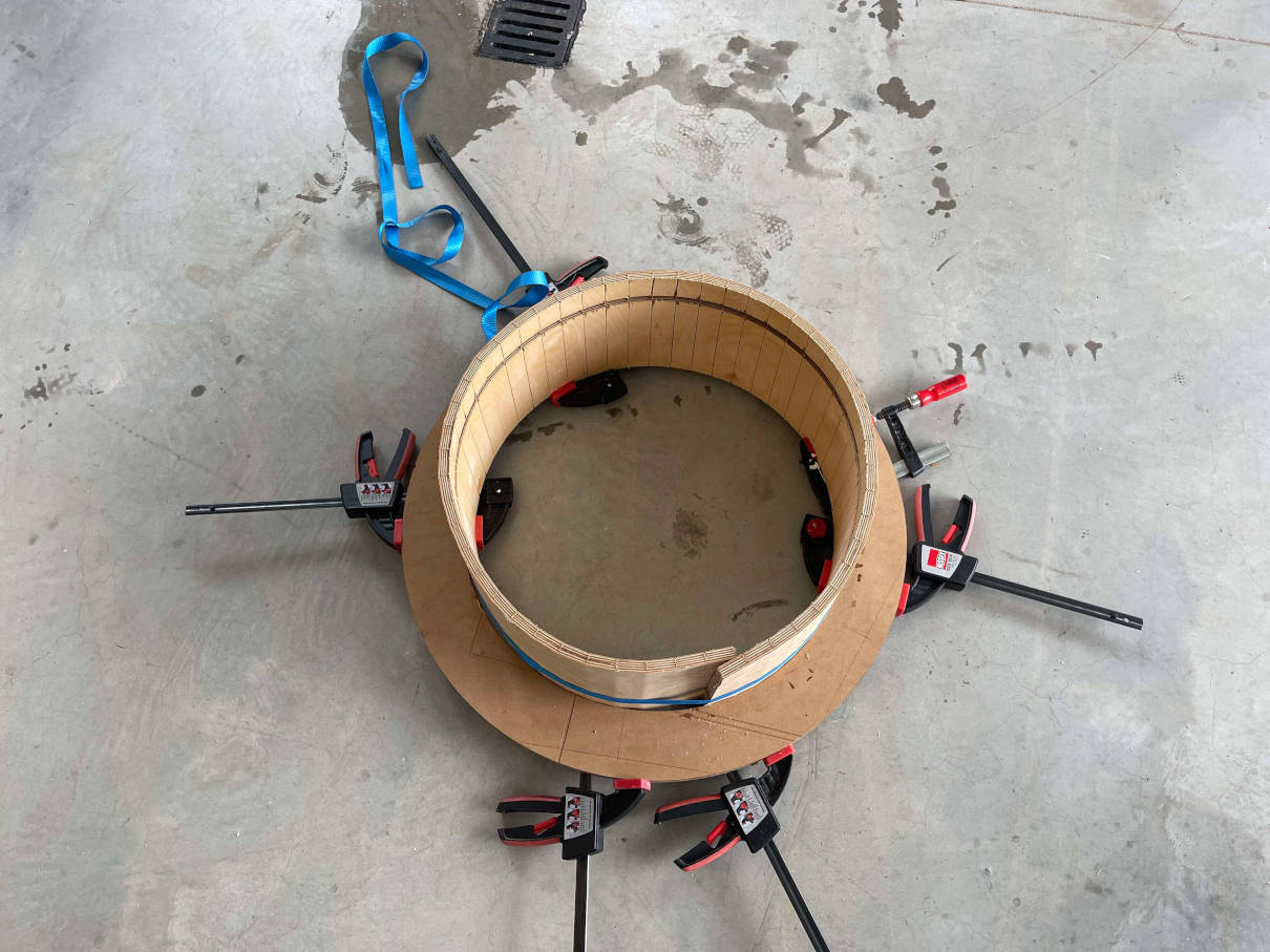
Trying to "force" the piece into place 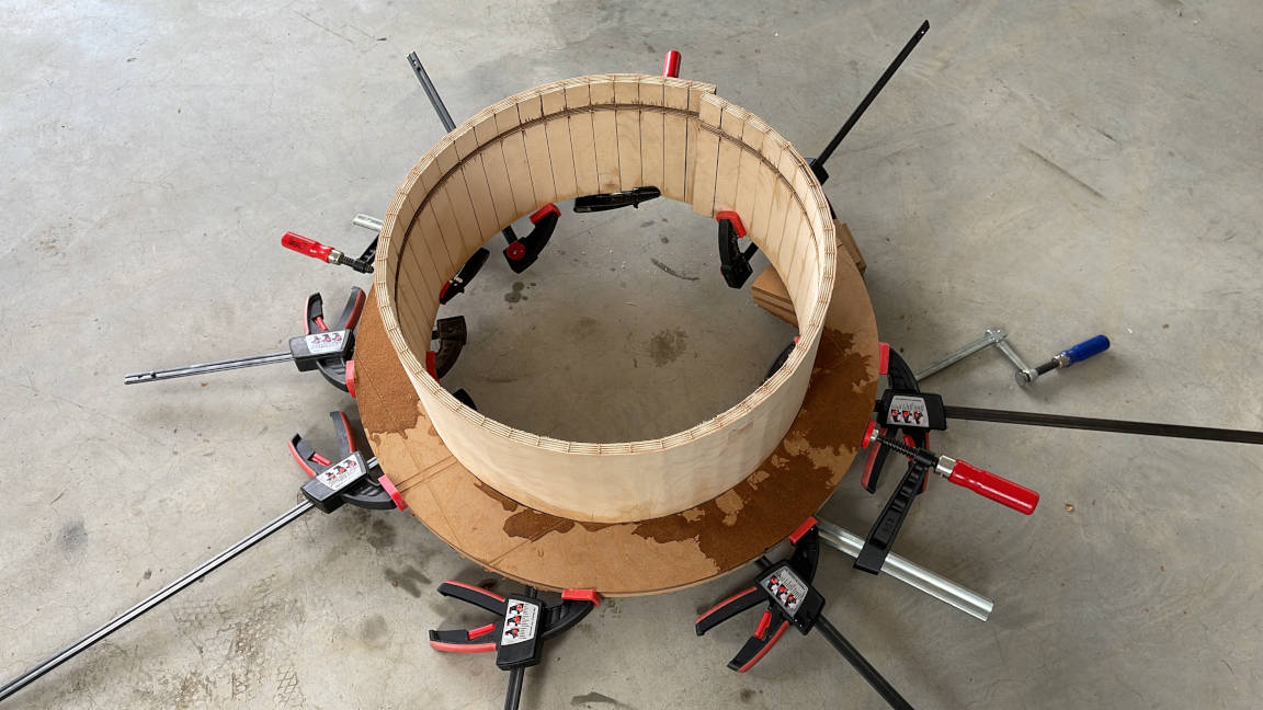
Other Angle of the process The next day we removed the clamps and freed the piece of plywood from the "mold". The process really was successfull as the wood did not want to turn into a straightened out form again. Next up we tried inserting the gear insert. This way we could align the base piece with the help of the hear insert and already fuse them. For this task I needed three people to help. We slowly but surely used wood glue and hammered in the gear insert centimeter by centimeter, until we moved around the gear insert. Next up we finished the process by more vigorously hammering from one end to the other to get the gear insert to really lay flat with the pocket inside of the base piece. For long time force we also used clamps together with a piece of the cut out gear to interface with the clamp and the gear. Part of the process can be seen in the images below:
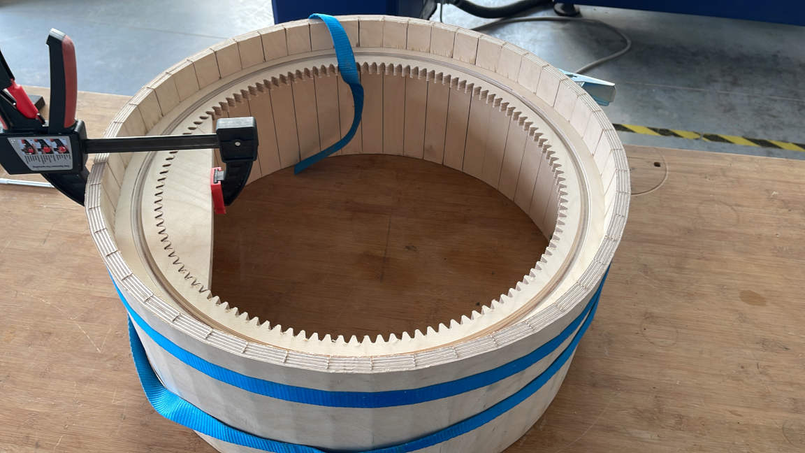
Fusing the Gear insert with the Rounded Base 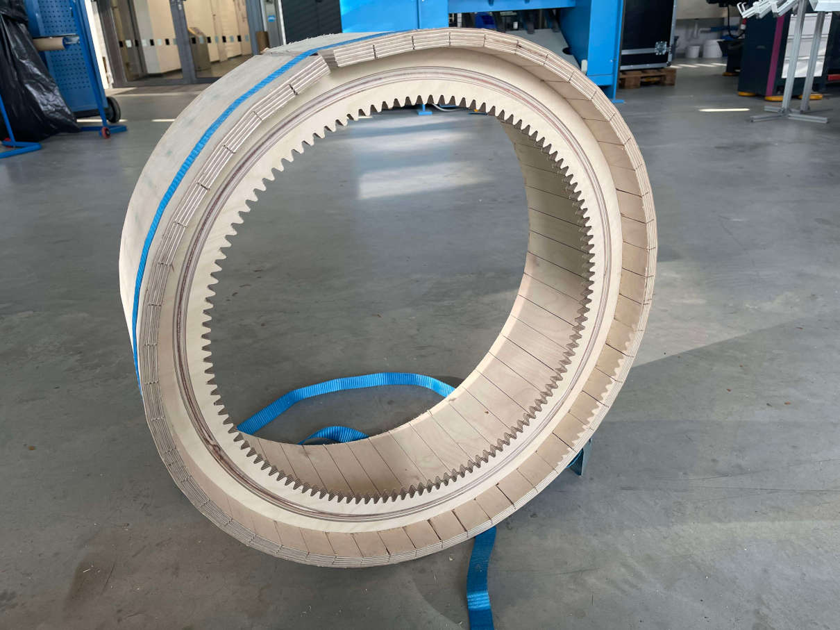
Fusing the Gear insert with the Rounded Base 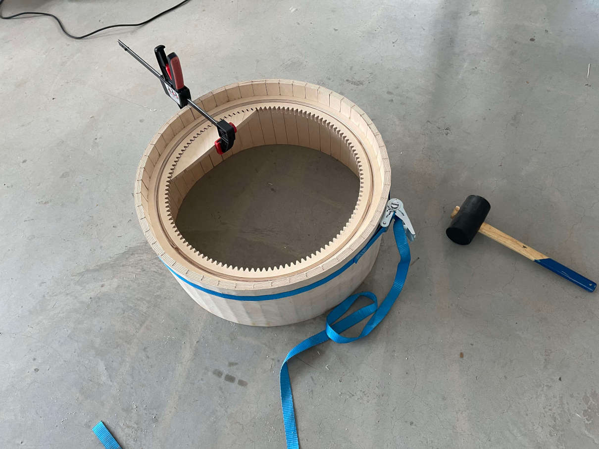
Fusing the Gear insert with the Rounded Base -
Central Bottom and Top (15mm Plywood)
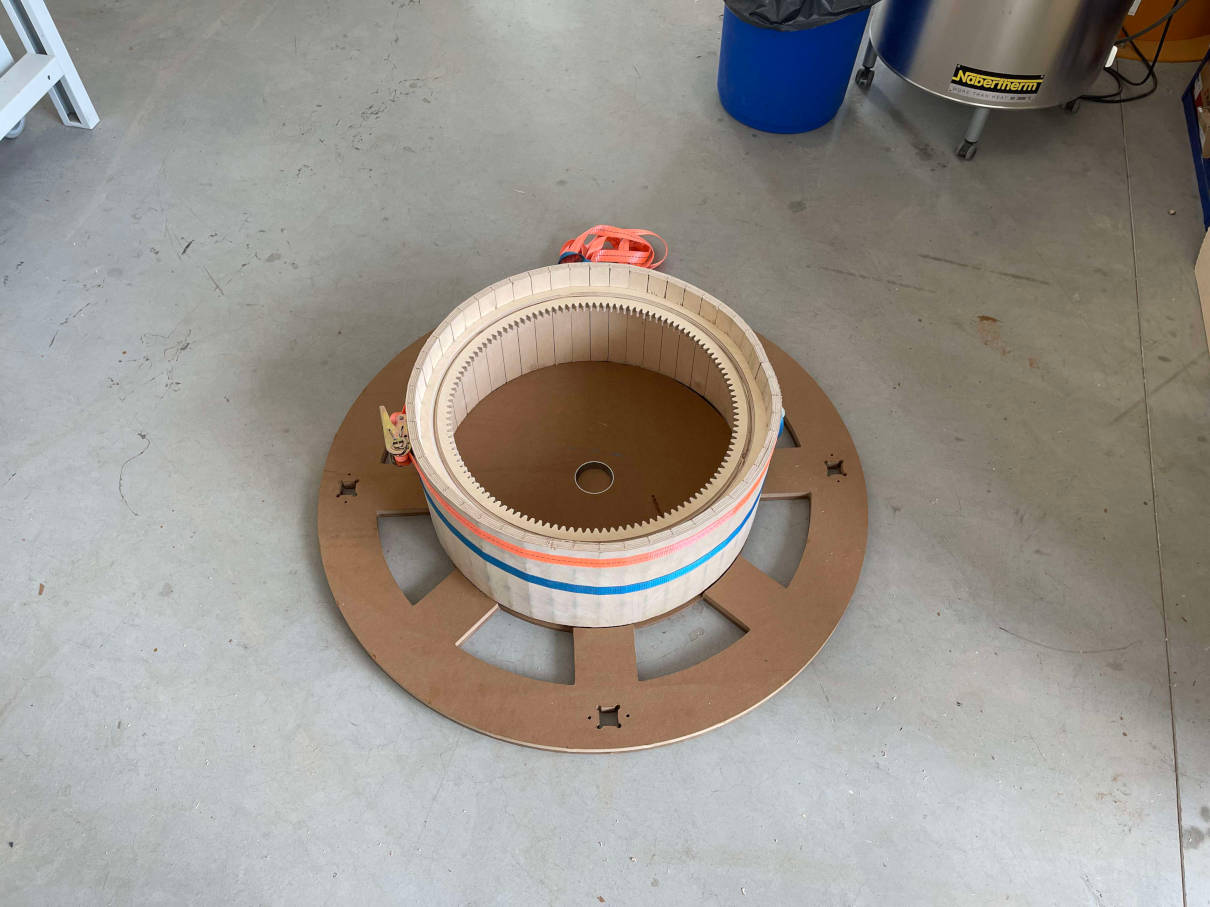
Apart from deciding on where to put the cutouts for both motors, these two pieces are realtively normal. The one important thing I had to have in mind while milling them, is that the bottom piece had to be milled with its bottom side facing up, to be able to cut the groove for the steelballs. The fact, that it needed this groove was also the reason why I chose to go with the CNCs internal CAM processor and a layered DXF file again instead of using Fusion360s CAM processor. The cutting process was really straight forward and at the end I had both parts cut really quickly.. For a short proof of concept and a really anxious moment for myself I really wanted to try anduse the steelballs and interface the gear insert of the base with the bottom rotating platform. After inserting the rounded base inside the MDF base, I went ahead and placed almost all of the 100 12mm steelballs we had ordered for this inside the gear inserts groove. I placed the rotating base ontop and was immediatly relieved when I noticed that the rotating base was not touching anywhere else and only interfaced with the steelballs. I even made a short video to celebrate the first mechanically moving part of the machine:
The Gear Insert with the steelballs inserted in the Groove. First test of rotational movement! -
Planting Rings (18mm Coated Plywood)
While the planting Rings were more or less just as straight forward as the bottom and top of the rotating platform, they came with their own challenges. First of all I needed to know the dimensions of the planting pots I was going to use in the project. The planting pots I ended up using and buying can be found in the list of materials further up on this page. I just measured one of the pots at a specific Height and went ahead and made a cutout for a pot on four equally distributed points per ring. At first I wanted to cut the Rings as a whole. The problem was, that this would have wasted so much stock. I would have needed two whole sheets of stock to make three rings. As a solution for this problem, I cut the planting Rings in Half, right through two of the aluminum profile pockets. This way, I could nest them In a way, that allowed me to cut all three rings on a single piece of stock with minimal waste. For this I just created a rectangle in Fusion the same size as the stock (A little smaller to be extra sure) and tried to get all of the six half rings inside the box. Once I was successfull, I then went ahesd and used the usual Fusion360 CAM functions such as drilling, pocketing and 2D contouring. The cutting process of these pieces can be seen in these pictures:
Pocket Cuts of the planting rings 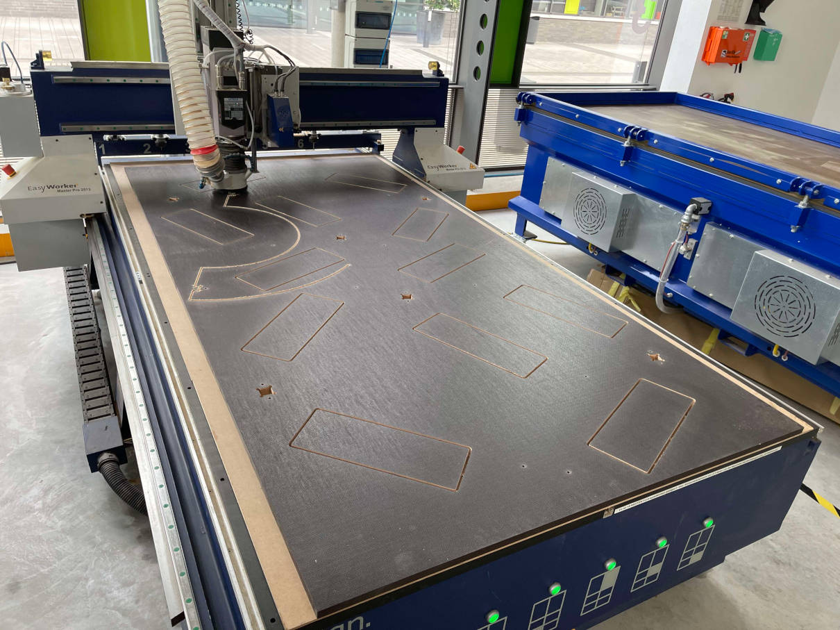
Contour cuts of the planting rings 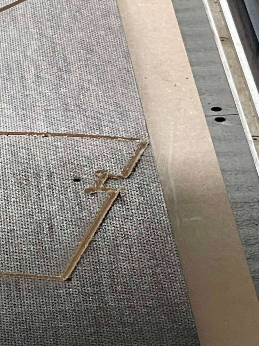
Using all the space available on the stock 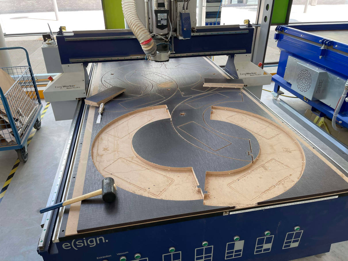
Removing the parts from the rest of the stock -
Toolhead (15mm Plywood)
The last thing I designed was the toolhead, as it was reliant on the distance between the two center aluminum profiles holding it upright. It was also very much relying on the HIWIN linear railings and the interface width with the HIWIN linear rail carts, which I wanted to mount from inside to the toolhead. In hindsight I made a few very dumb choices here and due to time and stress made many really stupid mistakes. For one, I just ignored the HIWIN rail in my width calculation for the toolhead. Secondly I also ignored the HIWIN rail when making the pocket for the aluminum framing for the top and bottom of the toolhead. This resulted in a very quick change up of the toolhead in the last minutes of this project. The images below are version one, with the misjudged widths. Version two however really only changed the widths and pockets of the toolhead, so I kept the images, since i find them quite telling:
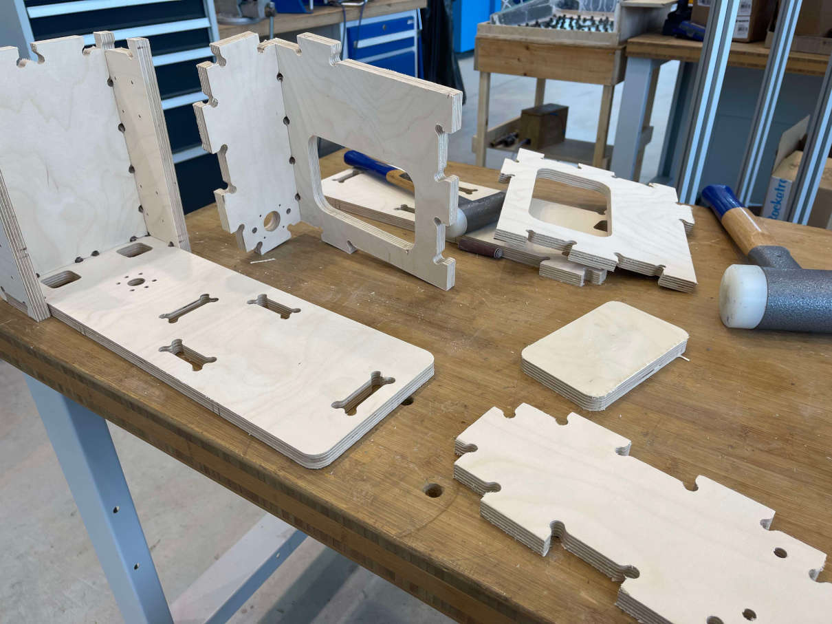
Half assembled toolhead 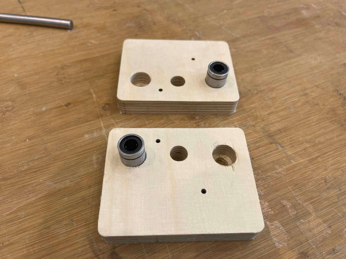
The two parts of the moveable part for the z axis 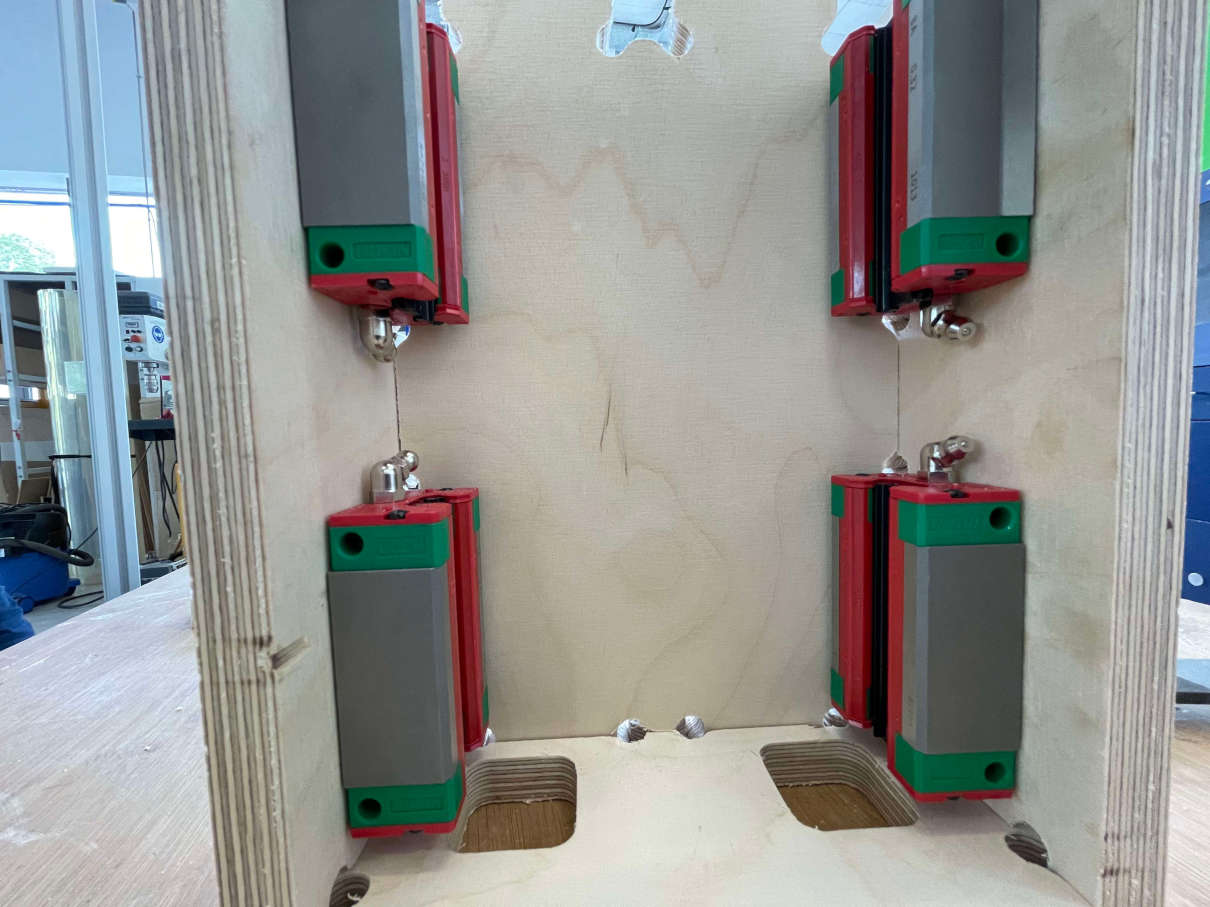
HIWIN linear Rail carts mounted to the Toolhead 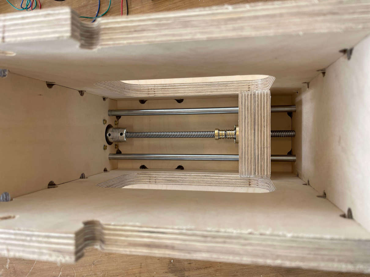
Complete Z-axis as seen from the top 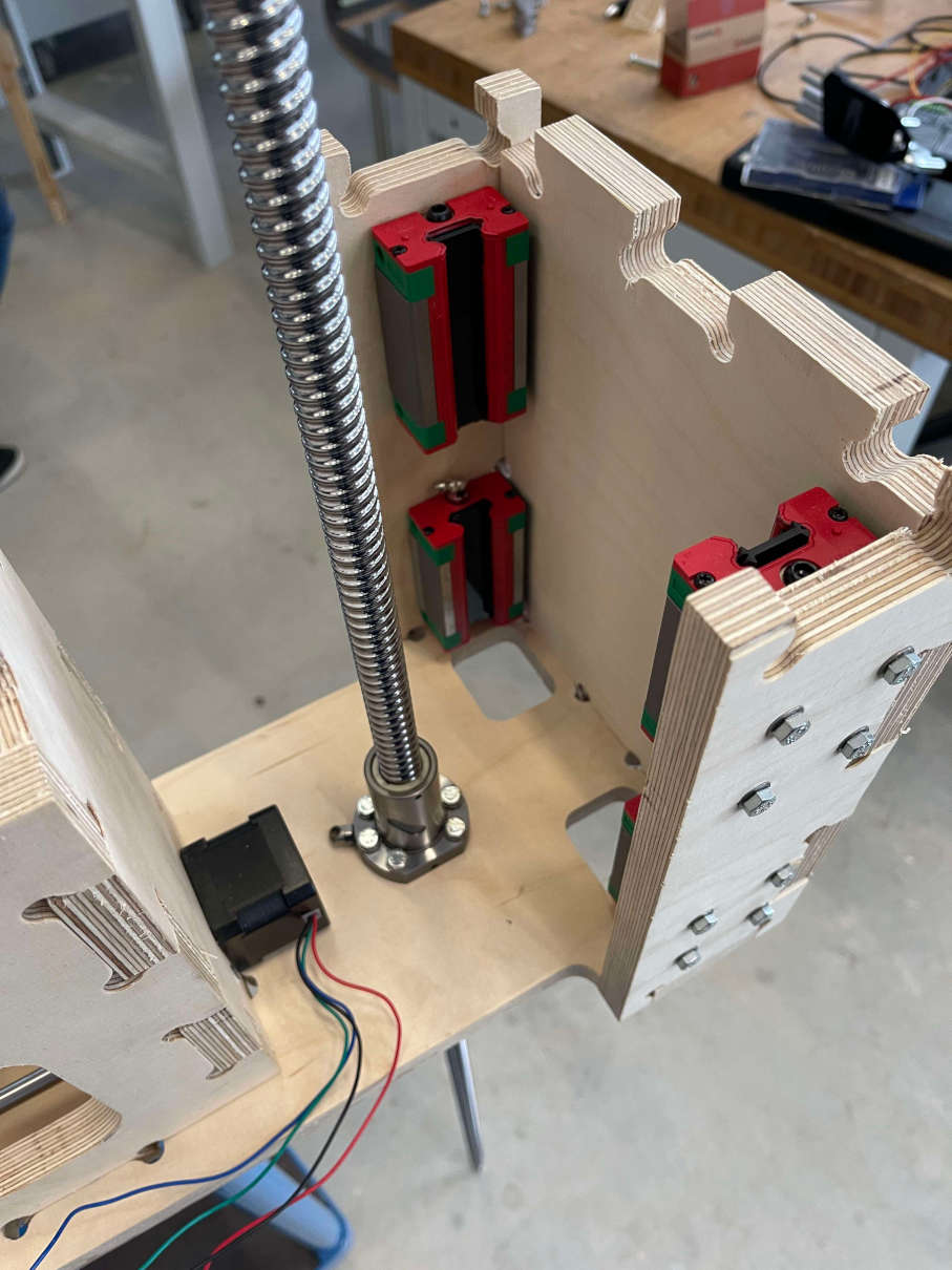
2000mm Ballscrew installed in the toolhead
Embedded programming
-
GRBL
I already talked a little bit about GRBL in my Machine Building Week. For this project I reverted GRBL back to its standard configuration and changed the homing sequence once again. This time, since i wanted to move each Axis individually during homing, I changed the homing cycle in such a way, that after the z axis is homed, X and Y are NOT homed simultaniously but rather one after another. This is very simply done by just changing the following lines in GRBL's
config.hfile:#define HOMING_CYCLE_0 (1<<Z_AXIS) // REQUIRED: First move Z to clear workspace. //#define HOMING_CYCLE_1 ((1<<X_AXIS)|(1<<Y_AXIS)) // OPTIONAL: Then move X,Y at the same time.To these lines:
#define HOMING_CYCLE_0 (1<<Z_AXIS) // REQUIRED: First move Z to clear workspace. //#define HOMING_CYCLE_1 ((1<<X_AXIS)|(1<<Y_AXIS)) // OPTIONAL: Then move X,Y at the same time. #define HOMING_CYCLE_1 (1<<X_AXIS) #define HOMING_CYCLE_2 (1<<Y_AXIS)Since this time around I had no problems with janky connections through my self made vias, the installation process of GRBL was so much simpler and really straight forward. You begin by flashing an Arduino UNO with the Arduino as ISP program to upload the 328p bootloader onto the empty chip on the GRBL board. If this was done successfully you wire up the two Boards in the following manner:
- Pin 10 of the Arduino Uno to Reset of GRBL
- Pin 11 of the Arduino Uno to MOSI of GRBL
- Pin 12 of the Arduino Uno to MISO of GRBL
- Pin 13 of the Arduino Uno to SCK of GRBL
- 5V out of Arduino Uno to one of the 9 VCC Pins of the GRBL Board
- GND of the Arduino Uno to one of the many GND Pins of the GRBL Board
Once successfully connected this way, simply select the Arduino Uno as your microcontroller within the Arduino IDE. After that choose
Arduino as ISPas the programmer, select the correct port of your Arduino UNO and pressBurn Bootloader. Once this runs through you can disconnect the Uno from the GRBL Board as from now on we can upload to theGRBL Board using a serial communication. To upload GRBL, inthe Arduino IDE just go toFile > Examples > grbl> grblUpload. As the Microcontroller you select the Arduino Uno and just press upload. GRBL should now be successfully be installed on your Board. -
Main Control Board
The whole process of getting my SAMD21E17A Board to life is basically entirely the same process I used for my SAMD21E17A Board in Embedded Programming Week. I just exposed the bare minimum of needed Pins to use the JTAG connector and uploaded the Bootloader with a JTAG programmer using EDBG and the Bootoader from Mattairtech's Github page. As with the LED Game Board, this process went flawless and without hickups. Now that the Board had a Bootloader I just needed the Mattairtech SAMD21 Board Library for the Arduino IDE, which you can simply add by using the Board manager. With this isntalled, I dialled in all my settings (which are the same as for the FAB LED Game), and began programming. The code is as of now sadly untested as it errors out everytime, so take the below code with a HUGE grain of salt, I will try to update this page here as soon as I have resolved the Issue on why the code isnt working:
#include <List.hpp>
#include <Adafruit_seesaw.h>
#include <Wire.h>

//Adress of Motor Driver Board
const int MDBAdress = 0x50;

//Sensorobjects (Ringnumber_Sensornumber)

Adafruit_seesaw ss11;
Adafruit_seesaw ss12;
Adafruit_seesaw ss13;
Adafruit_seesaw ss14;
Adafruit_seesaw ss21;
Adafruit_seesaw ss22;
Adafruit_seesaw ss23;
Adafruit_seesaw ss24;
Adafruit_seesaw ss31;
Adafruit_seesaw ss32;
Adafruit_seesaw ss33;
Adafruit_seesaw ss34;

Adafruit_seesaw soilSensors[12] = {ss11, ss12, ss13, ss14, ss21, ss22, ss23, ss24, ss31, ss32, ss33, ss34};

//Adresses of Sensors I2C (RingNumber_SensorNumber)
const int sensorAdresses[12] = {0x36, 0x37, 0x38, 0x39, 0x40, 0x41, 0x42, 0x43, 0x44, 0x45, 0x46, 0x47};

//Pot Center Positions From Absolute Zero
const float positions[12][3] = {{0.0, 0.0, 0.0},
								{0.0, 0.0, 0.0},
								{0.0, 0.0, 0.0},
								{0.0, 0.0, 0.0},
								{0.0, 0.0, 0.0},
								{0.0, 0.0, 0.0},
								{0.0, 0.0, 0.0},
								{0.0, 0.0, 0.0},
								{0.0, 0.0, 0.0},
								{0.0, 0.0, 0.0},
								{0.0, 0.0, 0.0},
								{0.0, 0.0, 0.0}};

//Hardcoded max Numbers for all axis (just for now, endstops will be added later)
const float maxX = 0.0; //+180 degrees
const float minX = 0.0; //-180 degrees

const float maxY = 0.0;

const float maxZ = 0.0;

//Feedrates per motor
const int feedX = 3500;
const int feedY = 2000;
const int feedZ = 1000;

//GCode
const String absolute = "G90";
const String relative = "G91";
const String coolantOn = "M8";
const String coolantOff = "M9";

//GRBL
const String aproveAlarm = "$X";
const String homingCycle = "$H";

//Watering Threshold
const int wateringThreshold = 400;

//List to keep track of which plant need watering
List<int> indices;
int currentWateringIndex = 0;

//Helping Variables
int state = 0;
int prevState = 0;
float nextPos[3]  = {0.0, 0.0, 0.0};
bool wateringNeeded = false;
float currentPosX = 0;
float currentPosY = 0;
float currentPosZ = 0;
String currentCommand = "";
float wateringZ = 0.0;
float rotateHalfPot = 0.0;
String returnedValue = "";

//DataVariables
uint16_t soilData[12];

//Pins for brake toggling
const int enableIn = 8;
const int brakeOut = 7;

void setup() {
	//start Serial
	Serial.begin(115200);
	Serial.println("Started");
	pinMode(enableIn, INPUT);
	pinMode(brakeOut, OUTPUT);
	//Start Wire for all I2C Soil Sensors
	//startWire();
	//delay(1000);
}

void loop() {
	//Listen for Brake Signal
	Serial.println("Check");
	if(digitalRead(enableIn) == LOW){
	digitalWrite(brakeOut, HIGH);
	}else{
	digitalWrite(brakeOut, LOW);
	}
	//Run Statemachine
	switch(state){
	case 0: //Gather Sensor Data
		//GatherSoilData();
		//state = 1;

	case 1: //Look up if some plant needs watering (200 - Very Dry; 2000 - Very Wet)

		if(indices.isEmpty()){
		for(int i = 0; i < 12; i++){
			if(soilData[i] < wateringThreshold){
			indices.addLast(i);
			}
		}
		}else{
		currentWateringIndex = indices.getValue(0);
		nextPos[0] = positions[currentWateringIndex][0];
		nextPos[1] = positions[currentWateringIndex][1];
		nextPos[2] = positions[currentWateringIndex][2];
		indices.removeFirst();
		wateringNeeded = true;
		state = 2;
		}

	case 2: //If plant needs watering, take first plant that does so and calculate path to send to GRBL Board
		if(wateringNeeded){
		wateringNeeded = false;
		calculatePath();
		state = 3;
		}else{
		state = 12;
		}

	case 3: //Execute Command by sending it over Serial to GRBL Board
		Serial.println(currentCommand);
		prevState = 3;
		state = 100;

	case 4: //Move z axis in watering position
		currentCommand = absolute + "Z" + wateringZ;
		Serial.println(currentCommand);
		prevState = 4;
		state = 100;

	case 5: //activate solenoid through GRBL coolant system
		currentCommand = coolantOn;
		Serial.println(currentCommand);
		prevState = 5;
		state = 100;

	case 6: //Move first direction
		//X + first
		currentCommand = relative + "X" + rotateHalfPot;
		Serial.println(currentCommand);
		prevState = 6;
		state = 100;

	case 7: //Move second direction
		currentCommand = relative + "X" + (-2*rotateHalfPot);
		Serial.println(currentCommand);
		prevState = 7;
		state = 100;

	case 8: //MoveCenter
		currentCommand = relative + "X" + rotateHalfPot;
		Serial.println(currentCommand);
		prevState = 8;
		state = 100;

	case 9: //Coolant Off
		currentCommand = coolantOff;
		Serial.println(currentCommand);
		prevState = 9;
		state = 100;

	case 10: //Z Axis retract
		currentCommand = absolute + "Z0.0";
		Serial.println(currentCommand);
		prevState = 10;
		state = 100;

	case 11: //Move to absolute zero
		currentCommand = absolute + "X0Y0";
		Serial.println(currentCommand);
		prevState = 11;
		state = 100;

	case 12:
		delay(60000);
		state = 0;

	case 100: //Wait for ok from GRBL
		while(Serial.available() == 0){
		//Wait
		}
		returnedValue = Serial.readString();
		if(returnedValue == "Ok"){
		state = prevState + 1;
		prevState = 0;
		delay(250);
		}else{
		prevState = 0;
		state = 999;
		}

	case 999: //Error State
		Serial.println("An Error occured please check the whole System and restart!");
		delay(1000);

	default:
		Serial.println("Something unforseen happened, please check everything and restart the whole system!");
		delay(1000);
	}

}

void startWire(){
	for(int i = 0; i < 12; i++){
	if (!soilSensors[i].begin(sensorAdresses[i])) {
	Serial.print("Soilsensor ");
	Serial.print(i+1);
	Serial.print(" could not be reached!");
	}
}
}

void GatherSoilData(){
	for(int i = 0; i < 12; i++){
	int soilMoisture = soilSensors[i].touchRead(0);
	soilData[i] = soilMoisture;
	}
}

void calculatePath(){
	//NEEDS REWORK!!!!!!!!!!
	float wayToMoveX = nextPos[0] - currentPosX;
	float wayToMoveY = nextPos[1] - currentPosY;
	float wayToMoveZ = nextPos[2] - currentPosZ;
	currentCommand = buildCommand(absolute, wayToMoveX, wayToMoveY, wayToMoveZ);
}

String buildCommand(String movementType, float x, float y, float z){
	return movementType + "X" + x + "Y" + y + "Z" + z;
}
As you can see, the code is just half done for now, since I still need absolute real world positions for every planting pot. I also need to then come up with a working translative calculation of the way, the machine has to take in Order to get to where it wants to go, without tripping over the -180 degrees; +180 degrees stop (The X-Axis Endstop). Will update here as soon as possible.
-
Adafruit I2C Soil Moisture Sensors
Let me preface this section with one thing. The last time I had this much fun digging through code and finding my way through stuff to change something thats not usually changeable, ahs never occured. The feeling of accomplishing something like this is really great, and even myself as someone who knows how to code in different languages really felt a great rush of happiness after successfully pulling of what I will decribe now :D!
I never planned to do anything remotely close to programming with these Adafruit I2C Soil Moistiure Sensors. They however come with (in my eyes at least) one big flaw, and that is, that their I2C adress ist stuck on the value
0x36. The only thing the User can do from the outside, is to to Bridge these two pads on the backside of the sensor: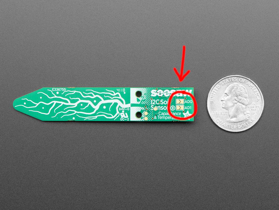
The two Pads that can be brdged to change the Sensors I2C adress (Image taken from Here) These pads work in a way, that if you Bridge Connector AD0, it will add 1 to the adress and if you bridge AD1, it will add 2 to the adress, which of course means, that if you bridge both connectors, 3 will be added to the adress, resulting in the following I2C adress spectrum for this sensor:
[0x36, 0x37, 0x38, 0x39]After thinking about different solutions siuch as using three different sercoms on my Main controller for I2C, I just triedt to find out more about the Soil Sensors. To my surprise Adafriit has their entire code for their whole sensor setup available online on their libraries Github page. Here I literally sank in hours trying to understand what was going on, how this library was built and so on. After hours and hours of searching and understanding slowly how the sensor works, I found out that the three unconnected pads on the back of the sensor are literally just Reset, SWDIO and SWCLK, which meant that I could just like the SAMD21E17A upload a custom made firmware through a JTAG connection, since the Stemma Soil Sensor was using the SAMD10D14A MCU. I was very very excited as Adafruit also openly shares their firmwares for all their sensors. To cut short on all of this code hunting: In the end I literally only had to change one single line of code in the
board_config.hinseesaw > boards > soiland rebuilt the firmware folder afterwards using edbg:#define CONFIG_I2C_SLAVE_ADDR 0x36The
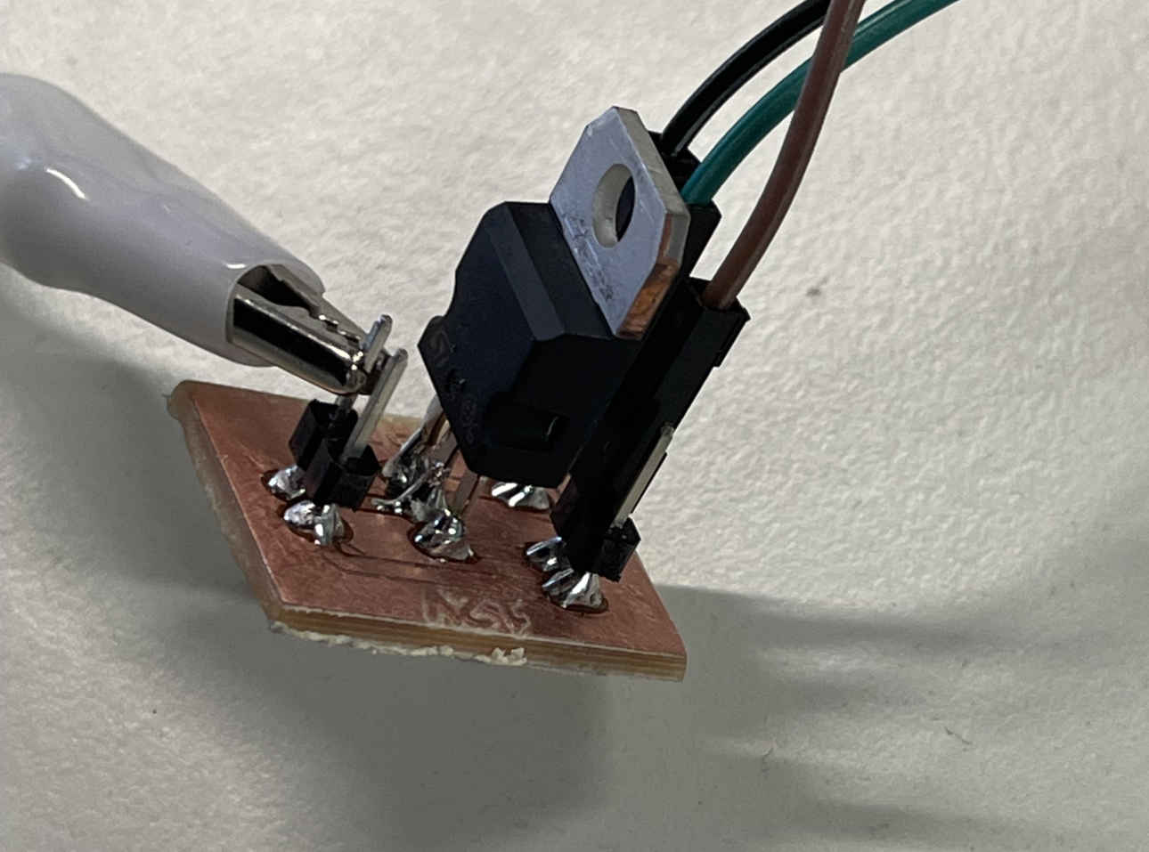
CONFIG_I2C_SLAVE_ADDRvariable is then later on used, when the chip is trying to calvulate its actual adress with the eventually brdiged parameters in mind. In my case I need three firmwares to get 12 sensors to work. For thefirst plant ring I can just go ahead and use the vanilla firmware on the chip. The second Ring can then start with the address0x40, while the third ring starts with the adress0x44. At this point in time we only had two of these sensors for testing at the lab (the rest still has not arrived sadly), one of which was completely broken, as it only spat out max values when trying to read sensor data. Naturally, since I did not want to brick the only functioning copy of this sensor we had on hand, I tested my approach with the broken sensor, alraedy thinking that it would never ever work. This was the sensor after i soldered a cable very loosely to each of the pads on the back: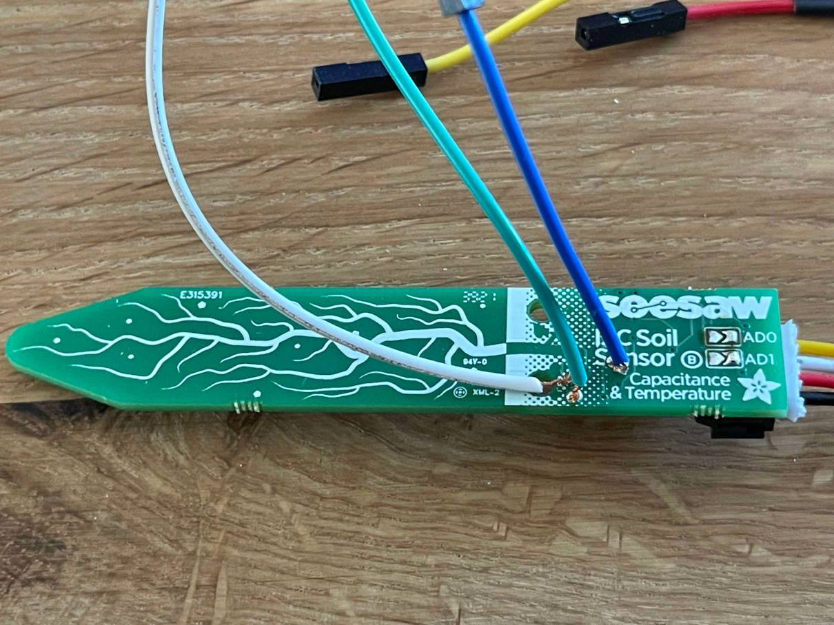
The soldered cables on the back of the sensor The cables had the following function:
- Blue: Reset
- Green: SWDIO
- White: SWCLK
edbg -bpv -e -t samd10 -f seesaw-soil-0x40.binI pressed enter, and... it just freaking worked. EDBG stated that the target was a SAMD10 Chip and uploaded the firmware without a problem. I was majorly excited that this worked. But the best part to this whole thing is, that the sensor was freking working now. My only possible explanation for this, is that it was never flashed in the factory before and so was just doing nothing. Not only did I manage to change the adress rangeof these sensors with a changed firmware, I also brought a believed to be dead sensor back to life! This felt so incredibly good, that I just had to include it here :D
-
Attiny1614 Boards
Since I already talked about this Board further up, I want to make it short here. Since I managed to solve the I2C adress problem directly with the sensors, I theoretically do not need the Attiny1614 MCUs on these Boards at all. Just for testing purposes I loaded them up with code that goes through all four sensors and displays the data via serial, so I wamted to show this code here atleast. In the future, these Chips maybe used for other purposes within the machine, I still havent fully decided, but it sure is nice to have them at my disposal if I want to use them:
#include <Adafruit_seesaw.h> //Library to read out the Soil Sensors data

//SoilSensor objects
Adafruit_seesaw soilSensor1;
Adafruit_seesaw soilSensor2;
Adafruit_seesaw soilSensor3;
Adafruit_seesaw soilSensor4;

//Arrays to hold received data
uint16_t caps[4] = {0, 0, 0, 0};
float temps[4] = {0.0, 0.0, 0.0, 0.0};

void setup() {
	//Begin Serial communication and communication with the four Soil Sensors

	Serial.begin(115200);
	//Adresses for first plant ring
	soilSensor1.begin(0x36);
	soilSensor2.begin(0x37);
	soilSensor3.begin(0x38);
	soilSensor4.begin(0x39);

	//Adresses for second Ring
	//soilSensor1.begin(0x40);
	//soilSensor2.begin(0x41);
	//soilSensor3.begin(0x42);
	//soilSensor4.begin(0x43);

	//Adresses for third ring
	//soilSensor1.begin(0x44);
	//soilSensor2.begin(0x45);
	//soilSensor3.begin(0x46);
	//soilSensor4.begin(0x47);


}

void loop() {
	gatherSensorData(); //gather data
	sendData(); //send Data
	delay(30000); //Wait half a minute
}

void gatherSensorData(){
	//Gather Capacitance data from every SoilSensor on this Level
	caps[0] = soilSensor1.touchRead(0);
	caps[1] = soilSensor2.touchRead(0);
	caps[2] = soilSensor3.touchRead(0);
	caps[3] = soilSensor4.touchRead(0);

	//Gather Temperature data from Soil Sensors (Not very acurate)
	temps[0] = soilSensor1.getTemp();
	temps[1] = soilSensor2.getTemp();
	temps[2] = soilSensor3.getTemp();
	temps[3] = soilSensor4.getTemp();
}

void sendData(){
	for(int i=0; i<4; i++){
	Serial.println(caps[i]);
	}

	for(int i=0; i<4; i++){
	Serial.println(temps[i]);
	}
}
Output Devices
-
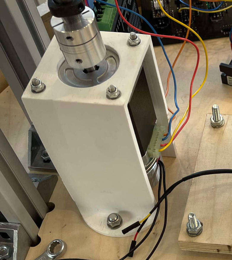
Nema23 Stepper Motor for X-Axis
This stepper motor is as standard as it gets. A Nema23 Motor, thats being driven by a Leadshine DM542EU Stepper driver Block, which in turn gets its signal from the GRBL Board. This DM542EU Driver supplies the Motor with 24V and a dipswitch selectable amount of current. The Microstepping can also be selected vial dipswitches on the top of the Driver Block. The Motor is then interfaced with the 3D printed Gear you can read up about further above. Between the Gear and the Motor is a coupler that slots into the 6.35mm stepper motor rod and on the other end into the 10mm gear rod. The motor itself is laying ontop of a second 15mm plate to allow precise distance for the gear to interface with the wooden gear insert below. The motor is then bolted down on this mounting plate and through the rotating base plate with screws, nuts and washers.
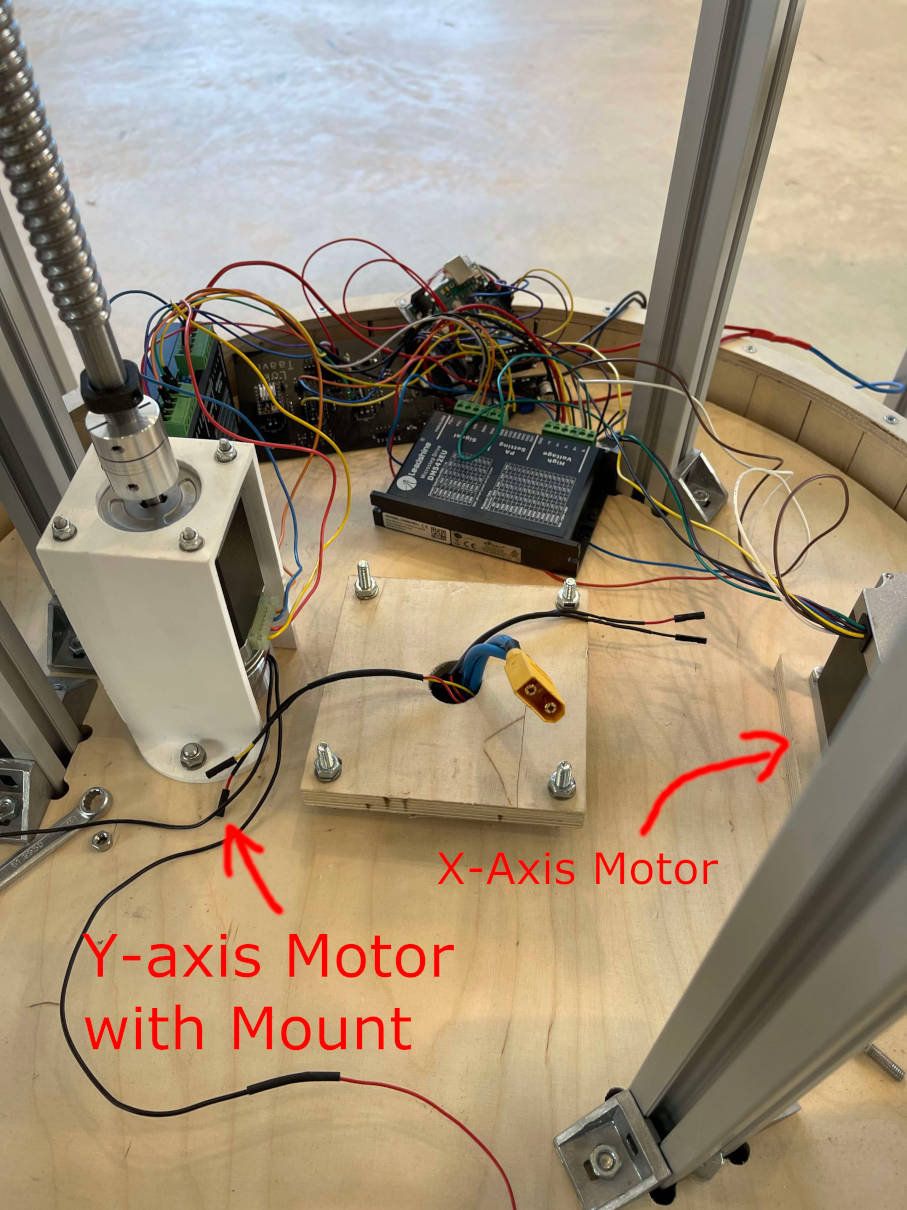
The mounted X-Axis Motor to the right of the picture -
Nema23 Stepper Motor with brakes for Y-Axis
This Motor almost gave me a heart attack. Ahemd suggested I try outone of these Stepper Motors with an integrated brake, so we ordered one from what seemed to be a local vendor. The motor itslef took almost three weeks to arrive though, so I could only pluck it into the machine during the last few days before the presentation. Ontop of that I probably read somethingwrong in the motors datasheet, as the 3D printed adatper to bolt it onto the rotating base plate, was a little bit to narrow (no problem, since pla is a bit flexible) but also a bit too tall, so as of right now, the motor is levitating above the plate until I reprint a shorter version of the mounting bracket.
This Motor is being driven by a Leadshine DM556EU Stepper Motor Driver, which is almost identical to the DM542EU. We just ordered both versions because of our curiosity towards these drivers. Like the 542EU the 556EU is getting ist signal through the GRBL Board and the 24V to drive the motor through an external power connection. As with the 542EU the 556EU can also be set using dipswitches for the current and the microstepping! The brake of this motor is active low, which means, that as long as no 12V is provided to the brakes, it stops the motor from moving with a holding torque of about 3.3Nm.
Just like the Nema23 for the rotational axis, this motor is connected through a coupler going from 6.35mm to 10mm into the 2000mm ballscrew.
The mounted Y-Axis Motor to the left -
Nema17 Stepper Motor for Z-Axis
This motoris the only motor, that uses as stepper driver, which the GRBL Board was designed for in the first place: A SilentStepStick based on the TMC2100 chip. As you can already see in this picture, the Stepper driver is already in its place and ready to use, by just plugging in the motor right next to the driver block:
To the right you can see the SilentStepStick plugged into the Z axis of the GRBL Board For the rest of the Z-Axis, I used almost exactly the same pieces as for the X- and Y-Axis of my ISS Tracker from Machine Buidling Week. The 12V for this motor are provided by the GRBL Board directly. The Microstepping can be changed with the three exposed CFG pins of this axis.
-
Solenoid Valve
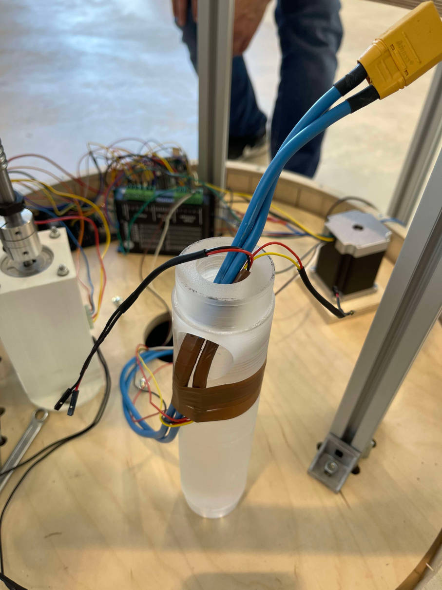
This Valve basically functions in the same manner as the Brake for the Y-Axis motordescribed above. The valve is normally closed and if given 12V, it opens and lets water run through. Just like with the Brakes I managed to control this behaviour with a simple mosfet and a 5V logic signal, that itself is connected to GRBLs Coolant flood output. This means that through the M8 GCode command, I can open the Valve and through the M9 GCode command I can close the valve, pretty neat! The solenoid is right now getting its water through a water bottle further up at the machine. Through the power of gravity, the water is pushed to the Solenoid and if it is the opened, the water is being forced through the solenoid throiugh the gravity, which then is running out of the solenoids output, which goes through a second tube out of the front of the machine!
The mounted solenoid valve
Input Devices
-
I2C Soil Moisture Sensors
For measuring the Soil moisture level of each individual pot, I opted for the Adafruit STEMMA Soil Sensors, since the soil mositure sensors I used in Input week werent exactly the greatest and really jumpy in their behaviour. From testing I found the Adafruit sensor to be much more reliable and stable. Sadly they only come with a range of four possible I2C adresses, hence why I had to dig through their open source files (Thanks Adafruit!) and change stuff around, which you can read up much more about in the embedded programming chapter on this page.
-
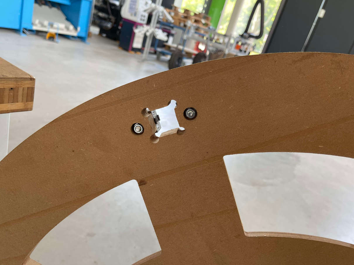
Endtops for X-/Y-/Z-Axis
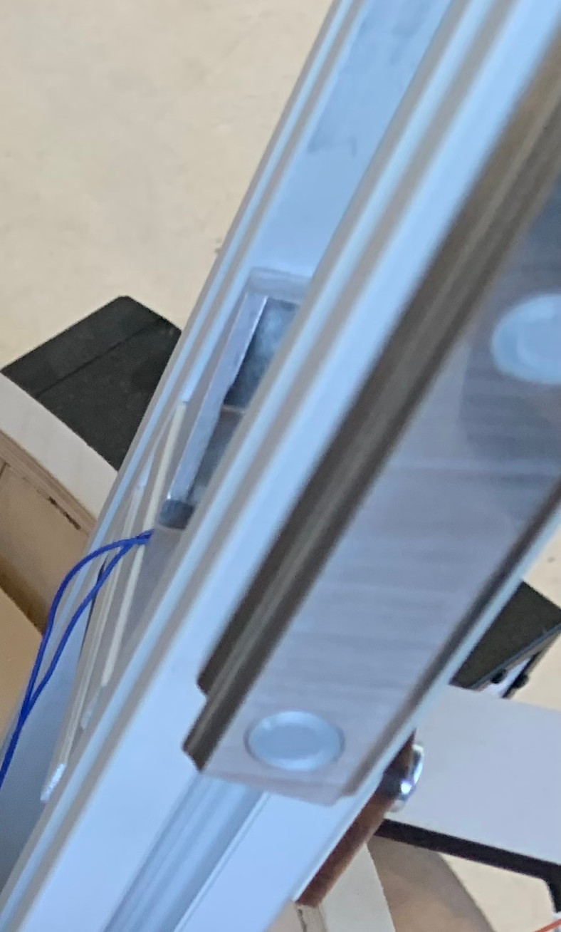
These three endstops are needed to successfully build a homing cycle with GRBL. They can be very easily connected to the pins at the top of the GRBL Board as you can see in the following picture:
At the top of the Board there are pins for two Endstops per axis
Network and Communications
-
I2C
Since I already explored I2C greatly during my Networks and Communications Week, I really wanted to also use it in my final project as it offers simple two line communication with many devices and while I do not come anywhere near the limit of I2C, 12 Sensors are also no small amount. For I2C Communication I use the Wire library,as well as Adafruits Seesaw library, which is based on I2C Communication when starting communicating with a device. To see more about my implementation of the Soil sensors I2C interface, please look up the codeexamples furtherup the page under the embedded programming category.
-
Serial Communication
Apart from serial communication to program and read out data, the only important piece of serial communication is the connection between my main controller board and the GBRL Board, where basically just GCode commands are being sent and answers are being received.
Misceallaneous Stuff
-
Acryllic Staff
At first Ahmed suggested to me we use a aluminum rod with the right diameter to intercase between the bottom of the main base and the rotating baseplate. For this we found an almost fitting piece of solid aluminum rod and cut it to length with themetal saw. After that we used the lathe to try and drill a hole through the rod for cable management. In the end the plan was overthrown, since the tools at hand at the lab were just noch durable enough to cut this hole. Secondly the Aluminum rod was just about to small to fit through the two NTN Bearings. After searching in the Fablabs materials section a bit more we found a piece of acrylic rod that luckily enough fit the NTN bearings perfectly in diameter. We cut it to length on the saw again and then turned it on the laith. It was surrounded by brittle tape that was too old to peel away, so we cut it away with the lathe. This not only got rid of the sticky tape, but also gave the acrylic a frosted look, which really like! The acrylic rod together with thecables running through it can be seen in the pictures below. Sadly this piece can not be seen once assembled, which is why I wanted to really showcase it here!
The acrylic rod with the cables already fed through -
X Axis Endstop Wooden piece
Instead of Designing a single flat piece of wood, we just used the Circular saw and cut one of the cutouts from the plant rings to size to act as an actuator for the endstop. This piece of wood is mounted on one of the aluminum rods on the outside of the machine, while the Endstop itself is mounted on the rotating platform.
Construction phase
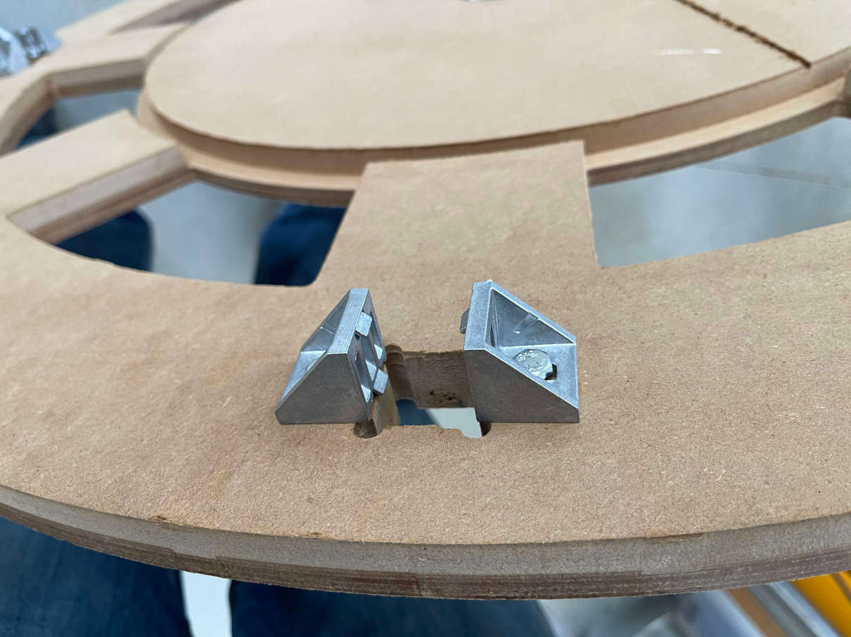
With this step the whole situation got serious. The next time Im designing such a machine I will certainly take a longer time with the design andmake it more user friendly to assemble, I can already tell you this much! The whole process also at most times needs atleast two persons. There is no way whatsoever to assemble this machine alone.The first part of the Assembly begins with the main base and the Aluminum profiles for the outside. These are secured with two aluminum angled brackets per profile (Four could do no harm and for the future would be a beter idea for stability). These Angled brackets are secured with a nut via a pocket for said nut in the bottom of the Base:
After this, I put the aluminum profiles in place and tightened them to the angle brackets. Afterwards the next step was connecting the six half planting rings. As I already mentioned above this step needed a little bit of sanding to be relatively smooth. With a little bit of force and patience, this was done quickly however. I simply tightened the six pieces to the aluminum profiles with further angled brackets from below. I paid attention to the distance of the planting rings and adjusted it, so that every ring could be reached withing the 1100mm range of the HIWIN linear rails.Next upwas thecenter rotating platform. Together with Ahmed, I also here tightened the four aluminum profiles to the base, aslwell as to the top. With Ahmeds help I connected the HIWIN Rails (they are quite heavy!) to the aluminum profiles and also already connected the Motor and the bracket for the second motor, as it would be alsmost impossible to tighten the motor down once the base is in place ontop of the inner gear. Before we could attach the central platform to the inner gear we first had to hammer in the rounded base into the pocket from the main base. This was not an easy task, as the rounded base was not perfectly round, due to some minor misalignment and whatnot. In the end, with the help of a few hammer swings and a little bit of clamping force, we managed to puch the round base into the main base however:
With the abse in place, I once again put all of the needed 12mm steel balls inside the groove of the gear insert. Nextup, we had to fix the Ballscrew with the toolhead in place.this was a really finnecky task, but we managed to do it. The rail carts slit over the HIWIN rails perfectly smooth! All that was now left to do, was putting the top lid on with more aluminum angled brackets and put this thing ontop of the steel balls. With this out of our way we isntalled the Motor with brake, interfaced the ballscrew and tested the mechanical function of the X and Y axis, which seemed to work just fine!
Onto the toolhead: The toolhead was already equipped with the nema17 motor, so all that was left to do was to put the solenoid valve ontop of themoving Z axis part. Short term we decided on hot glue. Long term I will also print a Mounting bracket for this guy. There was however no time left for this. We also attached one of the Mosfet circuits on the toolhead to control, the solenoid, as well as the Z Endstop.
Next up was the main cable work: We took a piece of carton and assembled all the electric components we would need to put on the rotating plate and put them onto the carton that waspreviously cutto size with the remaining space on the rotating plate in mind. After fitting everythin on there, we cut a piece out of the leftover black coated plywood with these exact dimensions. We fastened most components with screws, and othersthat had no screw holes with hot glue. We put the acrylic rod into place and fastened it slowly with nut in a cross pattern. Through the acryllic tube, we got mains power from the outside, provided by a lab bench power supply (for now). There are also the wires for power and I2C forthe sensors going through there. With all components in place, we mounted the lasercut mount for the Y axis Endstop and the piece of wood we cut to actuate the X axis Endstop. Finally we wired everything up and were now able to power everything and test. Sadly for now, as I already mentioned above, the code for the main controller is not working properly. Im working on fixing this issue ASAP.
Machine axes working
To not just stand here empty handed we took a Video for each individual axis moving, which for now shows the concept of the machine working just fine!
-
X Axis (Rotational Axis)
X-Axis in action -
Y Axis (Up and Down)
Y-Axis in action -
Z Axis (Solenoid forwards and backwards)
Z-Axis in action
Future plans
There are as of now many future plans for this machine. First of all I want to finish its main functionality. Then the current plan for the machine is to be situated inside of a greenhouse here at campus in Kamp-Lintfort. Looking further into the future I want to couple my masters thesis with this project. For this, the machine has to be connected to an existing MQTT network for data sharing and surveillance. Next up,I want to change the wholeIdea of the current toolhead. the next toolhead will be much smaller and equipped with hydraulics. It will (hopefully) be able to then lift and let go of planting pots, changing their position within the system. If this Idea is thought of further, you could even implemet a "manual insert", where a human could introduce a new planting pot into the system or request one of the current planting pots to be transported to him/her. I am for now, not quite sure what I want to do in the end. I am however sure, that this is certainly not the end of this project.
Time Management
Generally speaking my time management for Fabacadmy was quite okay. I managed most weeks without problem. A few unforseen problems made my time management really bad though. First came my last lectures from university at the beginning, but their time deficit was really easy to iron out. Then there was one Week in the middle, where I was sick for the whole week and could not get into the lab or even infront of my PC during this time. This week got pushed further and further into the schedule as I was mostly half a week behind. Lastly the worst thing that happened to me was the euthanization of one of my two cats. It came very unforseen and really threw me of greatly. While this happened I had a huge gaping holw of like 4 weeks of documentation lacking behind. In the end I managed to catch up with the documentation but I was very much hurried and under much stress to get done. Lastly came the final project, which for myself was a greatz example of triage. I first had much more Ideas for my final project which I then just pushed further back in time to after the fabacadamy and just settled on watering for now. This also ties in neatly to spiral development since my final project right now is more or less the minimum of functionality. With new sensors and functionality then comes a greater spiral. I do have to say though, that I have severly underestimated the time needed to build a machine this size. The milling time alone surpassed over 10 hours for all the parts, which is mind blowing I think. So in the end what i learned the most with this project, was to never underestimate how long a task will take, because all of the rest you planned gets delayed this way. Either this, or you have to decide to cut something from the project. In the end everything more or less worked out though, and I couldnt be more proud and happier about what I managed to accomplish even with all of the problems and sad stuff I encountered during Fabacadamy. I never gave up and pulled through at the end and Im really proud I did so!
Downloads
(For the most part most of the stuff from above happened within my main project, and due to time constraints I could not really keep it tidy, thats why its quite big and messy)
- Fusion360 File for Main Project (In parts as its too large else
- Fusion360 File for Toolhead (Including fixes (dxf files) because of miscalculations and stuff simply I forgot)
- Fusion360 File for Attiny1614 Board Cases
- KiCad Project Main Controller
- KiCad Project Attiny1614 I2C Board
- KiCad Project GRBL Board (With Gerber Files included)
- KiCad Project for the Mosfet Boards