
Assignment 8 - Computer-Controlled Machining
Assignments
Group Assignment(s)
- Do your lab's safety training
- test runout, alignment, fixturing, speeds, feeds, materials, and toolpaths for your machine
Individual Assignment(s)
- make (design+mill+assemble) something big (~meter-scale)
- extra credit: don't use fasteners or glue
- extra credit: include curved surfaces
Group Assignment
This weeks Group Assignment can be found here.
What I personally learned here, what was very good for my understanding of how a CNC generally works, are the names of the settings and what real world movement or action they refer to. After the Group assignment it was very clear what each setting in Fusion360 or the mills CAM processor did. I also learned, that the settings, we used for our test cuts, were quite optimal. Also I found out, that because I designed the Test cut the same way, I did my final project for this week (Same dogbones), that my Dogbones worked like a charme and fit together perfectly well!
Individual Assignment - Make Something Big
For this Assignment I already knew what I wanted to create! Since our space at home is filled with empty packages for our cats to sleep and relax inside, I thought of creating my very own Cat Relax Tower with a cosy cave and a second place to sleep on top. Since our Cats are quite large I planned for the resulting piece to be somewhere around 800mm tall and around 500mm wide, almost fitting on the meter scale. I began by looking at some reference pictures and immediatly knew that I wanted to have the entrance of the lower sleeping space in the form of a cats head. After I looked at enough different references I began my work by sketching out what I had in mind on paper:
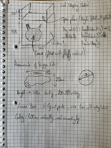
As you can see, I coarsly drew what I had in mind. I sketched up all the dimensions based on measurements I did on my Cats whil the stood upright or were sleeping (straight or curled up). With these measurements I had a rough estimate on the size I would need to have for the Box in order to fit my cats. After I sketched everything I began my work in Fusion360.
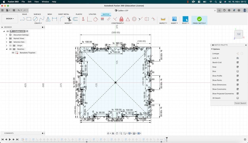
I began by creating the bottom piece of the Box. To have a consistent Width for the Box without factoring in the materials thickness because of Teeth on the side of the bottom panel, I decided to design the top and bottom panels with only slots. From the lecture and our local instructions I knew that I could not just use straight slots because the mill would not be able to create perfect 90 degree angles on inside corners. I decided to use the dogbone thechique we learned about in the lecture. For this I just created a circle on each inner corner and cut the lines away I would not need. After that I needed to reassign some sketch dimensions to have every line well defined again. Having everything well defined was the process that certainly took me the longest for all the parts. After the Dogbones were done, I was left with the following sketch, which then could be used for the Top and the Bottom part of the Box:
I have to add (As some sort of a PSA), that later on I learned about the existence of Plugins, which make it far more easy to apply dogbones. The one I got recommended is this one. For the fduture I will make sure, to give it a try!
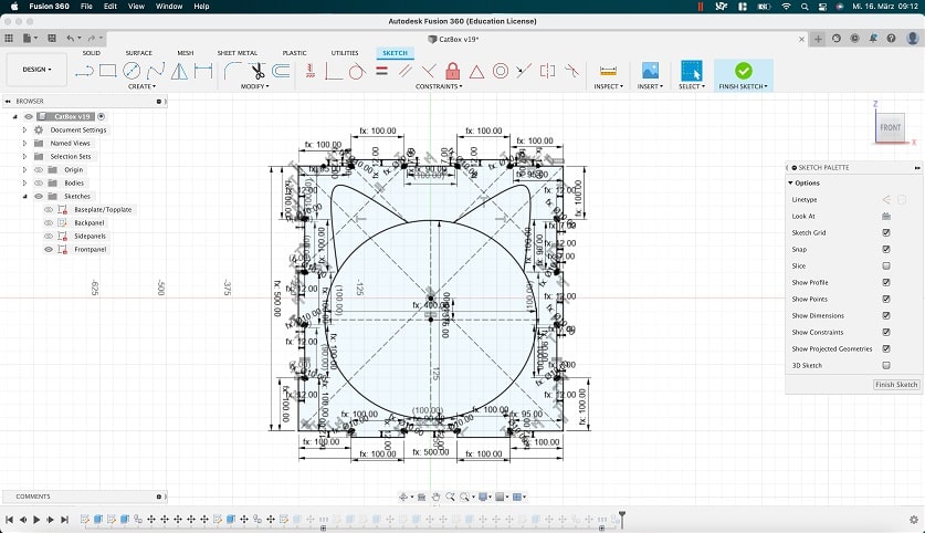
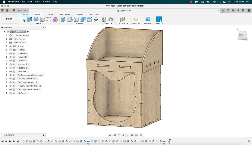
Next up, I decided to create the front or entry to the Box. This was the most difficult part of the process as I needed a long time to define the shape of a cats head as the entry. I started again with a simple square and creted my slots and teeth. After that I went ahead and created the dogbones for the inner corners, so that the cnc mill could mill the part. Finally, I added the cat shaped hole. For this I used an ellipse as the base shape of the cats head. For the ears, I defined two points along the outer perimeter of the elipse, where the ears would begin and end. Finnaly I used the conic curve tool to create a curve connecting the two prior points. As a third reference I used the outer edges of the Box. With these steps I had a well defined shape in the middle of the front panel, Which meant that I now could extrude the front. The sketch itself looked like this by the end:
For the Backpanel I just redid all the steps for the frontpanel without creating the Cat shape in the middle. The sidepannels were also quickly designed. Here I just needed to have in mind that ehe sidepanels do not need slots at all, because I decided to have the front and back use a mixture of teeth and slots. Here I made one mistake, that cost a little bit of time. I factored in the teeth when sketching the shape. This meant that the panels were as wide as the box should be, but with the teeth attached. This of course would not work, as the material would make the whole box larger on the outside, To fix this, I simply factored in the materials thickness. After that everything seemed to fit together, and I had created the underlying Box.
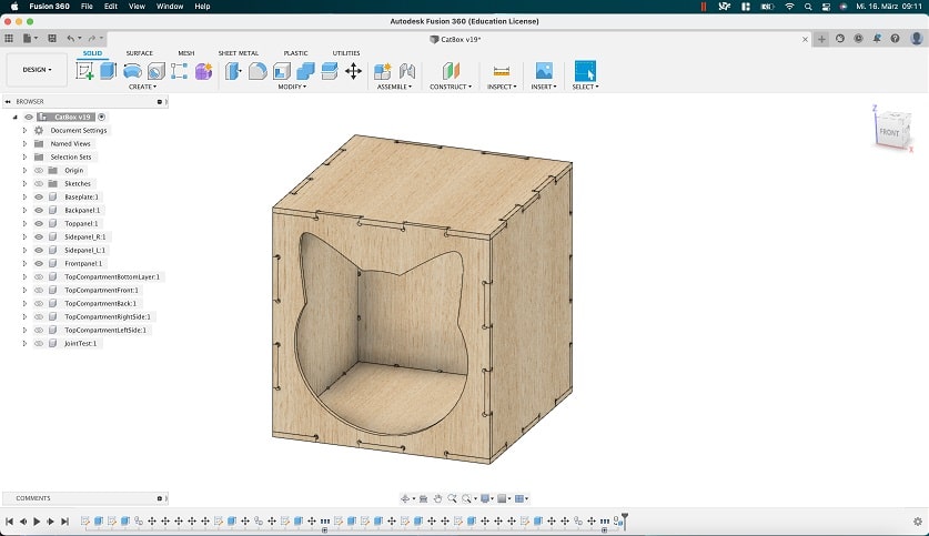
After the Box was done I started working on the top part. Since I did not want to create extra slots for the top part to slide into the top plate of the Box, I decided to design the top part in a way that it would slide over Box and sit there thight. I thougt of kind of a hat function. This way the top part would just slide onto the bottom box. For this to work in a way to allow a cat to sit there, I decided to have a bottom part of the top compartment that just sits ontop of the top of the box. This part would have teeth on all of its sides, so that the surrounding walls could just connect from each side. The sides themselves would not be connected however. I designed the bottom of the top part in a way that it would show the teeth exactly outside of the scale of the bottom box, so the sidepanel could slide in and work in a way that they would overlap the box to be kept in place, even if a cat wanted to jump up top to sleep there.
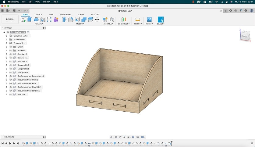
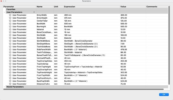
In the end this were all the parameters I used to define the sketches:
With the top part designed, it was onto the milling process! The first part of this process is the creation of the toolpath for our machine.
For this I used Fusion360, as we were not recommended the CAM tool that came with the CNCs software.
To start the process, I copied my project were I had all the pieces assembled and used the copied
project to lay every Item flat and next to each other, as tightly fitted as the 6mm flat end we
would use, would allow me to. Next up I switched to the Manufacture Submenu within
Fusion360. Here I set everything up like follows:
I started by adding a process. This is done via the top menu. Under the tab Milling
choose Setup > New Setup. This creates a setup in your tree structured browser on the
left. The setup consists of multiple tabs, each with their own settings. For our purposer we were
only using the tabs Setup and Stock. Under Stock I set the stock size to
Fixed size box to fit the pieces I laid flat. After that I just changed the Height of
the stock to exactly fit the material I was going to use (ca. 2500mmx1500mmx12mm plywood). In the
Setup tab under the subpoint Model I just clicked on every Model I wanted to Mill.
Under the sub point Work Coordinate System (WCS), I set Origin to
Stock box point and chose this point by clicking the button next to the
Stock Point setting. For our case it was important that the X-Axis is the longer axis
of the two. After the initial setup was done, I went ahead and added a 2D Contour job
by clicking 2D in the top menu of Fusion360 and choosing 2D Contour. This
will create a "2D Contour" job under the setup I just created.
As with the Setup Menu, the 2D Contour Menu also has many tabs with different settings. In my Case I
used Tool, Geometry, Heights, and Passes. Under
the tool tab I added a new tool by clicking on the select button. In the subsequent
menu, I added a new tool with the following settings, corresponding to the tool I was about to use:
- Tool Diameter: 6mm
- Number of flutes: 1
- Flute Length: 23mm
- Shoulder Length: 25mm
- Spindle Speed: 20000rpm
- Ramp Spindle Speed: 18000rpm
- Cutting Feedrate: 2000mm/min
- Ramp Feedrate: 1800 mm/min
- Lead-In and Lead-Out Feedrate: 1800mm/min
- Use Stepodown with 3.05mm
- Use Stepover with 3mm
- Coolant: Disabled
- Tool number: 1
Most of the values were taken from the tool itself, but others like the Spindle speed were tested
for a long time since the machine was first introduced in the lab. In the earlier times, the CNC
would not have such a high spindle speed as back then no one knew how far the machine is able to
push the spindle speed safely. Just with testing over time these settings were slowly becoming more
and more accurate. After the tool was added I switched to the Geometry tab. Under
Geometry I used the Contour Selection button to select all the contours I
wanted to cut. The important thing here is that I chose to select the lower contours which will be
important later on when im setting up the different heights in the Heights tab. Another
setting I did in the Geometry tab was adding tabs. Instead of using the automatic
function for this setting, I selected At points under Tab positioning and
went ahead and selected all the point on the contours, I wanted to have tabs at. The next tab I
adjusted setting in was the Heights tab. Here I adjusted all the settings in the following way:
- Clearance Height: 10mm from Retract Height
- Retract Height: 10mm from Stocks top
- Feed Height: 5mm from Top Height
- Top Height: 0mm from Stocks top
- Bottom Height: -0.2mm fron selected contours
I am setting the bottom Height to -0.2mm in order to be sure to cut through the whole stock, as it
could differ in thickness around the whole stock. The worst that could happen, is that I cut away a
little bit of the sacrificial layer. But its there for this purpose anyway. Next up was the
Passes tab. Here i left everything as standard and just activated
Multiple Depths, in order to not cut the whole stock in one go, but rather in multiple
cycles, each deeper than the one before. Corresponding to the tool stepdown setting from earlier I
set the Maximum Roughing to 3.05mm. After this was done, all settingswere dialed in.
Next up I simulated the 2D Contour milling by Rightclicking onto 2d Contour > Simulate.
Here I watched the sped up simulation to maybe cath some tool movements that sould not happen. I did
not see any and also switched to the tab Info. Here the user can see if any collisions
are occuring during the simulation. This was again not the case. At this point I was ready to create
the toolpath. Fot this the user has to Rightclick on 2D Contour > Post Process. With
the post processor given to us by our instructors, I processed the toolpath and saved it locally.
With the toolpath done, it was onto the mill!
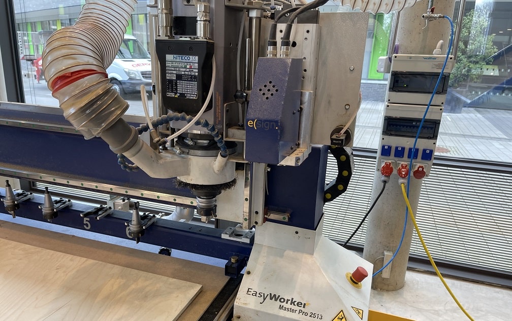
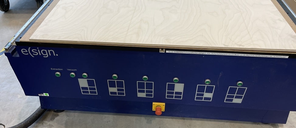
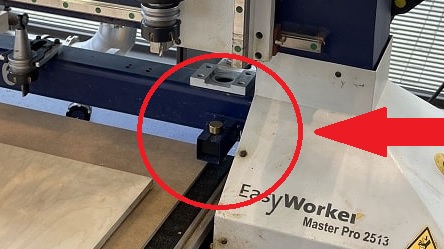
The mill in our lab is the elsign EasyWorker Master Pro 2513.
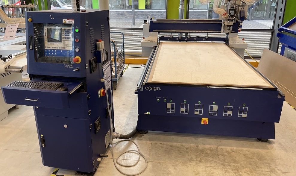
Before the milling could start, we were given an instruction to the machine and how to operate it safely. First we were given an overview on all of the parts of the machine. These include:
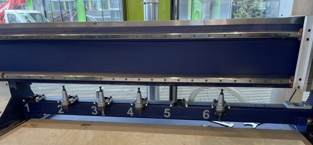
- The "Head" of the machine
- The tool slots
- The multiple EStops (One on the control station, One on the front of the bed, One on the back of the bed, One on each side of the Gantry)
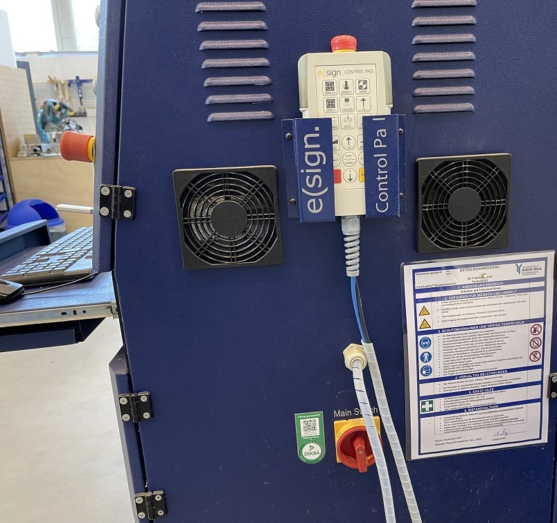
- The control station with the mains power switch, the pc and the remote for controlling the cnc mill
- The buttons for controlling the vacuum bed of the cnc mill
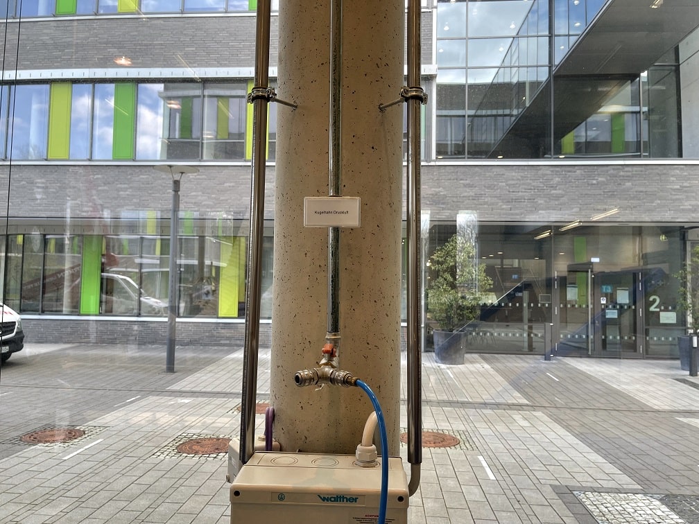
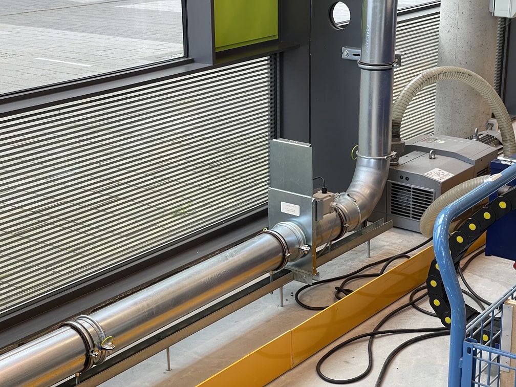
- A valve for the high pressured air
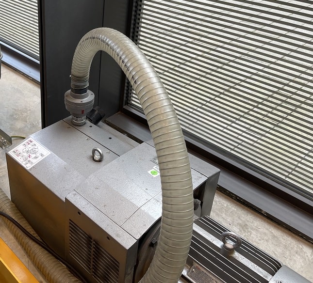
- The compressor that creates the vacuum for the bed
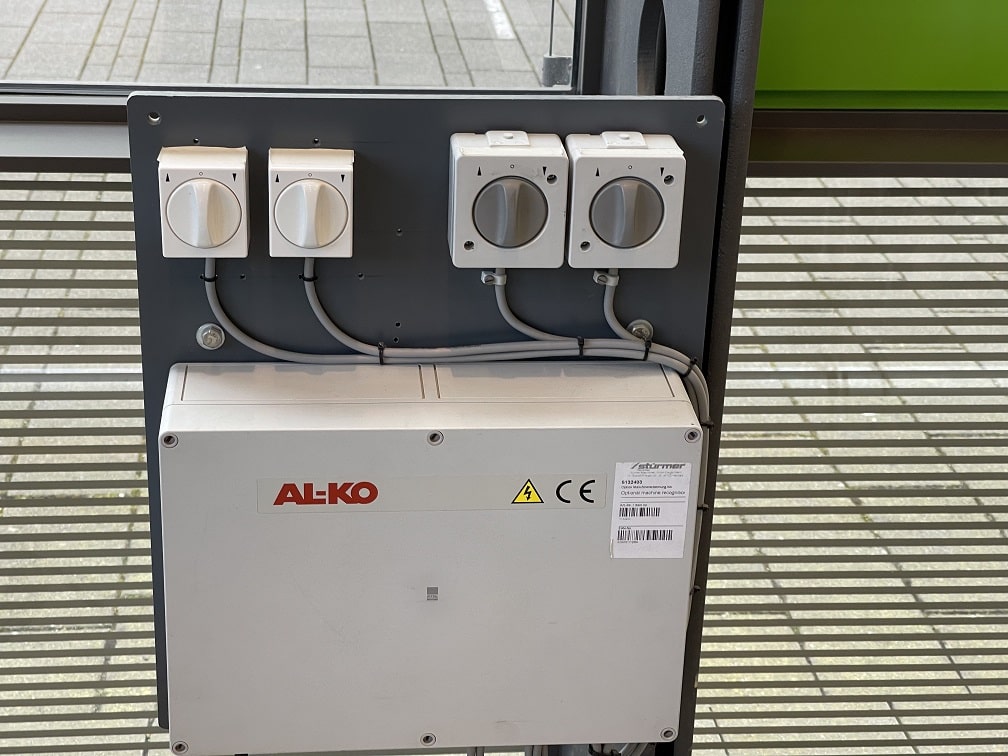
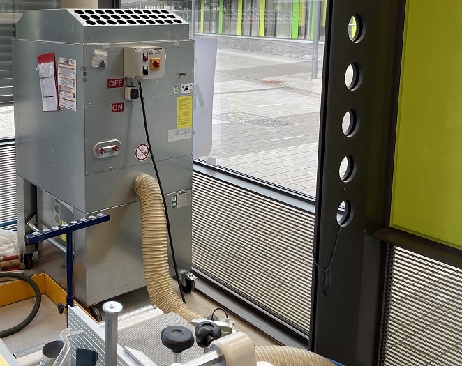
- The control station for the extraction pipes (This is there because there are multiple machines connected to the extraction, and to get the best pull to the extraction station, the ways to the other tools can be closed electricly)
- The extraction station with the On/Off switch
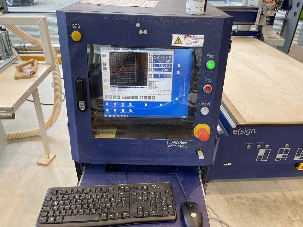
In order to operate the milling machine, we first loaded the bed with the material we wanted to mill. In my case this was a sheet of wood with ca. 2500mmx1500mmx12mm. Under this sheed of wood was a sacrificial layer of MDF. After loading the stock, we switched on the mains power, which turns on the CNC Mill, as well as the controlling pc:
Next up you have to press the reset button on the control station. After that we started the program
to control the mill on the pc. The program is simply called CNC. After the program has
started, the user can press the green start button. It is important, that the machine is started
AFTER the program and vice versa, that the machine is stopped BEFORE closing the program. Any other
order of operation could lead to a difference in information between the program and the cnc, which
later could theoretically lead to the mill crashing into the tool swapping station because it thinks
it has a tool it does not have at the moment. This is a huge problem, since our CNC does not have a
collision detection and simply would destroy itself this way.
After these steps we had to zero the Gantry. In the case of our CNC Mill, the zero point is the
bottom right of the bed from the perspective of the user that is tsanding infront of the control
station. In regards to the mill itself, this point is, the lower left point of the bed. This means
that in the image below, left to right is the Y axis and front to baxk is the X axis. This
difference in perspective was quite confusing, hence we needed to pay close attention at all times.
The process of zeroing the machine can either be done completely manually or with the help of a
projected laser cross for the X/Y-axis. Sadly, atleast at the moment our CNCs laser does not seem to
work and is super dimm. The part of the laser that is visible is even misaligned. This is why we set
the zero completely manually using the remote from the control station or the program itself to jog
the Gantry fast, slow or in different increments, up to a point where we were satisfied with the
gantrys position. For zeroing the z axis, the machine offers multiple automatic processes. First,
the machine is able to automatically find out the length of its current tool, with a sensor in the
back of the machine. Second, the gantry is equipped with a zeroing sensor, much like our Roland
MDX-40. As everything with the milling process, this step is a two person step. One person has to
hold the zeroing sensor while the other person has to start the process with one finger on the
escape button or the estop in case something goes wrong. The escape button always stops
the machines operation.
After zeroing, it is finally time to mill! First of we covered our ears and eyes with earbuds and
protective eye gear. AFter that, we opened the high pressure air valve, then
started the vacuum bed, with all vacuum zones actove in my case. Finally we started the exhaust,
while having a look if the exhaust to the mill is closed or open from when someone else used some of
the other machines connected to the exhaust. After these steps we loaded the toolpath created in
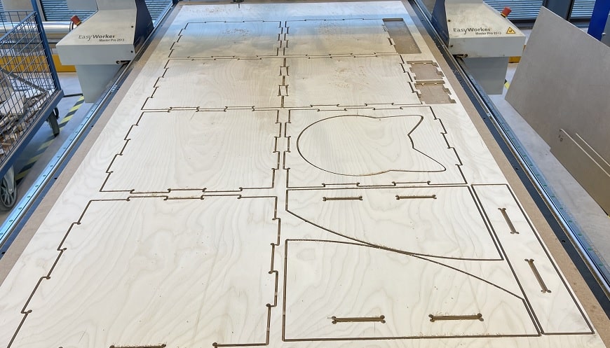
Fusion360. After taking a close look at the projected job in the software, we started the milling
process by pressing start in the program, or f4 on the keyboard. And of the machine
went:
The cutting timne was around 45 minutes and as you can see in the video, was not sucessfull at the end. Since the board was warped a bit, it was not fastened perfectly by vacuum and so the milling bit lifted the piece up. This was the moment I realized why exactly the operator has to pay attention all the time. Luckily we were prepared and quickly shut down the process. Why accidents like this have to be resolved quickly and taken absolutely seriously is described best with the picture of the piece of wood I took after removing it from the milling bit:
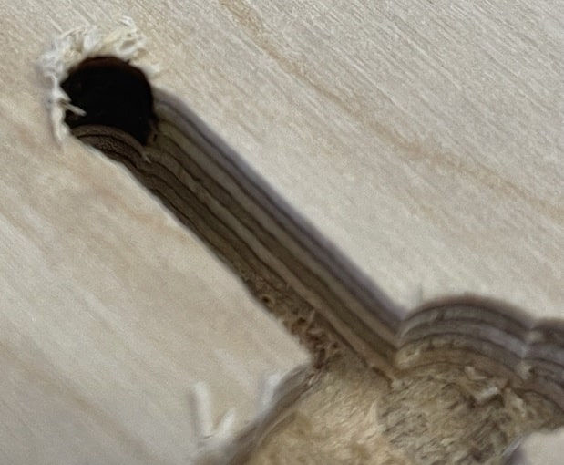
As you can see, the milling bit ran very hot while stuck to the piece, hence the black wood colouring inside the drill hole. With the exhaust running, this could lead to a burning particle combustinginside the exhausts collection bin, resulting in a massive fire. Everything went well here and we were quick enough to react to this accident.
Since the piece that was lifted was the second to last piece, I just realligned the piece that lifted off inside of Fusion360, deselected all contours that were already cut and post processed the new job and gave it to the machine. All of this can still be seen inside the timlapse. After this cut was done (successfully!), I started chipping away the taps that held the pieces to the stock. With the pieces removed, I noticed another mistake of mine. While laying flat all of the pieces in Fusion360, I really forgot one piece! The stock that was left was just about the perfect size to fit this piece vertically. So I made another toolpath with just this pieces contour selected. We rezeroed the X/Y-axis to be closer to the edge that defines the y axis, applied vacuum to the part of the bed, that is nearest to the user and loaded the toolpath. With almost perfect margins, the last piece was cut and I was done for the day!
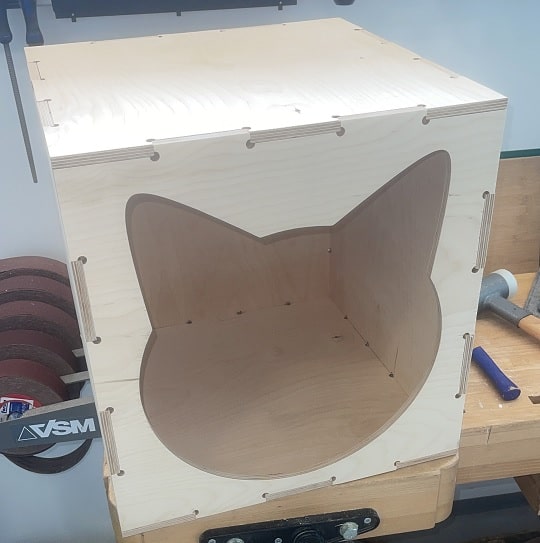
The next day I started the assembly process by first of all filing everything that needed filing. Since this piece will be used by my cats I was extra carefull to not have any splinters somewhere. This process was really tough and took me almost 3 hours to complete for every part. I chose to sand everything manually instead of using the rotary tool, in order to not sand away too much material, resulting in a two loose fit of the pieces. With everything sanded to my linking I began building this thing. Halfway through I thought I messed up while cutting because I made a mistake swapping two of the square boards, leading me to think one board that sould have beenonly cut one was cut twice and therefore another board was missing. This was just my honest mistake in sorting the pieces and in reality I had every piece I needed. For connecting, I used a spare part of wood and a rubber mallot to join the pieces together. I started with the wooden box and acieved this result:
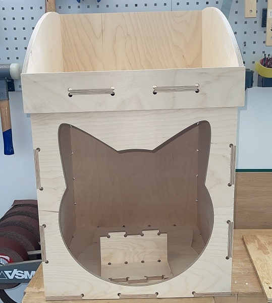
After that I assembled the top compartment which was much more difficult, as the side pieces are connected to the bottom piece somewhere in the middle and not on their sides. This also meant that they had a really really thoght fit. With the top part connected I tried stacking both of the parts together and was dissapointed as that was not going to happen. It did not fit really good. I started hammering everything even tioghter, sanded some kind of chamfer into the edges that would be meeting while connecting and finally used a router to create a every so small fillet on the bottom of the top piece to make the joining process much easier. At the end this is my result:
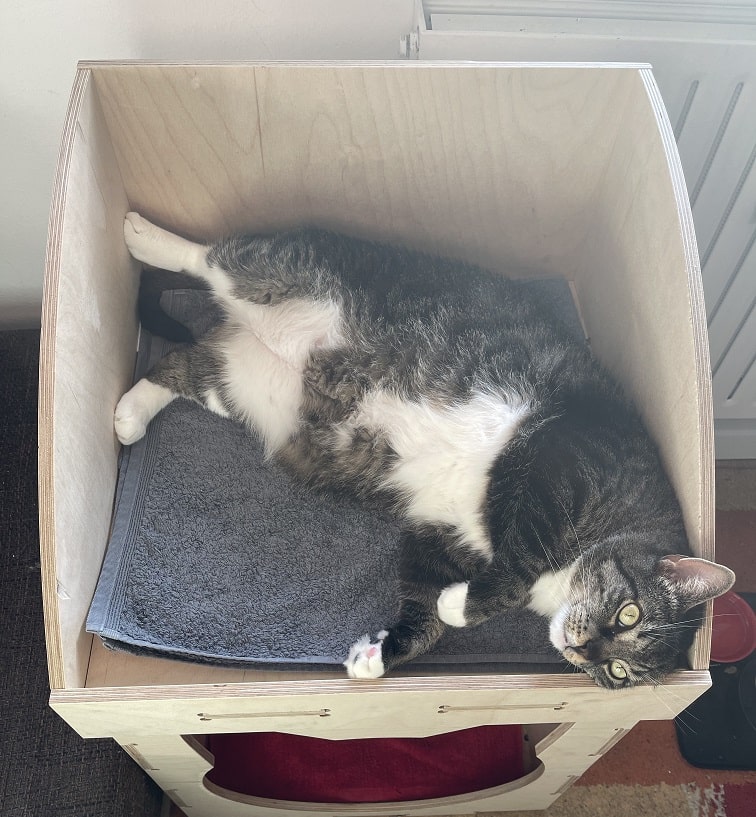
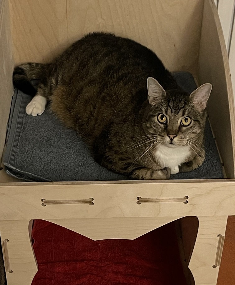
The Box is almost 800mm high and 524mm wide and deep. I am really really pleased with the final result and had very much fun while designing, milling and joining the pieces! And on top of that, our cats also seem to like their new chill out area :)
File Downloads