
Assignment 9- Embedded Programming
Assignments
Group Assignments
- Compare the performance and development workflows for other architectures
Individual Assignments
- Read the data sheet for your microcontroller
- Use your programmer to program your board to do something
- extra credit: try other programming languages and development environments
Group Assignments
This weeks Group Assignment can be found here.
Individual Assignemnt
This weeks Assignment was very cool but also a little stressfull for me. Since I have a programming background, I wanted to do something more than just using the one button and LED of my board from last week to do something. I just programmed one or two examples where the button switches between different LED modes. For this I also tried to use ARV and use C to program my board. While that worked and I can absolutely see the advantages of using the C programming languages in comparison to arduinos native language, I found that not using C was easier to get into for me personally. BEcause, while I have a programming background, the courses at our university sadly do not have us use many programming languages. Everything is more theoretical than anything else. So my experience in programming (roughly) covers only the following languages:
- Java
- JavaScript
- Python
- C#
- C/C++ (For one course a long while back)
- Structured Text for PLC programming
- Ladder Diagram for PLC programming
So while I had a Raspberry pi with me at home for ages now, I never really used it for embedded programming, hence why I was really looking towards this week, and finally getting a foot into arduino and microcontroller programming. What I gathered during our local class the most, was that almost all concepts I already knew stayed the same. The only thing different to "classical" programming would be to have a loop that manages the programm while running all the time. Its not as linear or distributed as the classical programming languages. At the same time it is almost identical to what I use at work anyway. PLCs also run on very tight loops, which threw me of very much at the beginning. But now I am used to it, so it was not much of a problem to get into the arduino programming.
But lets start from the beginning of this week. I first started by setting up my arduino environment on my laptop. This included the following steps:
- Downloading and installing the Arduino IDE from here
- Downloading the drivers for my FTDI based programmer from here
- Downloading AVR from here for testing out C programming
After installing everything, I tested out if my programmer worked on my board from the prevoius week and it did. So everything was working as intended. To get some usage out of my board from last week, which was Attiny1614 based, I created two diffreent programms that alter how the LED is behaving, one very simple, the other a little bit more complicated, with the pin structure from the datasheet in mind (Datasheet Download):
const int led = 10;
const int btn = 8;

void setup() {
	// put your setup code here, to run once:
	pinMode(led, OUTPUT);
	pinMode(btn, INPUT_PULLUP);
}

void loop() {
	// put your main code here, to run repeatedly:
	if(digitalRead(btn)){
	digitalWrite(led, LOW);
	}else{
	digitalWrite(led, HIGH);
	}
}
const int led = 10; //LED pin on my big Cat Board
const int btn = 8; //Btn pin on my big Cat Board
int state = 0; //state variable for switch case
void setup() {
  pinMode(btn, INPUT_PULLUP); //Register Button pin as INPUT_PULLUP
  attachInterrupt(digitalPinToInterrupt(btn), buttonPress, FALLING); //Attach interrupt to pin which trigger function everytime the signal is in FALLING state
  pinMode(led, OUTPUT); //Register LED as OUTPUT
}

void loop() {
  //Switch case to keep track of current mode (Four modes available)
  switch(state%4){ //Since state can get bigger than three, just take mod of state to get current mode
    case 0: //LED is permanently OFF
      digitalWrite(led, LOW);
      break;
    case 1: //LED is permanently ON
      digitalWrite(led, HIGH);
      break;
    case 2: //LED is blinking with an intervall of 100 between ON and OFF states
      digitalWrite(led, HIGH);
      delay(100);
      digitalWrite(led, LOW);
      delay(100);
    case 3: //Dynamic intervall => LED blinks faster and faster
      for (int i = 1000; i >= 0; i -= 25) {
        digitalWrite(led, LOW);
        delay(i);
        digitalWrite(led, HIGH);
        delay(i);
      }
  }

}

//Function gets called at button interrupt, adds +1 to the current state
void buttonPress(){
  state += 1;

}
While the first code basically only lights up the LED when the Button is pressed and held, the second code is a little bit more complicated. Here the User can toggle through four modes: LED Off, LED On, LED blinking at given interval, LED blinking faster and faster.
After this short test, I tried out C programming. This was the first time in at least 6 years and back then I did not really get the concepts of pointers and references, so I was bound to have a hard time testing out C programming. Our instructors did a really great job explaining how to program the boards using AVR. One problem was, that they were using ATMEGA328P based boards like the arduino uno. While the programming is more or less in line for the ATTiny1614, there were some distinct differences. The biggest difference for me was the pin allocation through ports and registers instead of just numbers. What also threw me off (even back when i first leanred C and C++), where the often used calculations with bit shifts, which I find really hard to grasp, because I never really got into them.
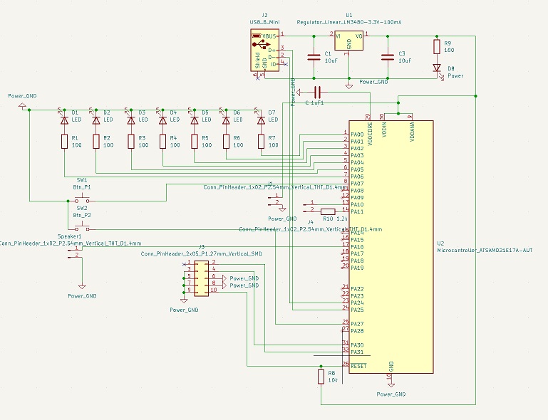
After this excursion into the realm of C programming, which showed me that I am still not the greatest fan of it, I sat there and thought of what I could do for this weeks project. I even ordered an Arduino uno with one of these beginner kits to test out different ideas I had in mind at home. After playing around for a day or two, I settled for one of my earliest Ideas I really liked: A one board, two person game. With the kit I bought, I put together a breadboard solution, so that I can try to program the game already, as it was the weekend already. I quickly noticed, that I would not be able to achieve this project with the ATTiny1614 just for the fact that it lacks the correct amount of pins I would need. I spoke to my instructor on monday and we quickly settled for the ATSAMD21E17. It offers more than enough pins for programming but needs some extra steps in order to be programmed. After going through said steps however, the board would be able to communicate directly to my machine via USB. I was directed to a project of Quentin Bolsee, where he used the ATSAMD21 to create a Devboard and even showed how to get the chip up and running. With this documentation in mind (Thank you very much Quentin!), ad a deep dive into the SAMD21s datasheet, which can be found here, I could begin designing the Board in KiCAD. Very much like last week, everything went well up unto the point where I had to connect everything to the ground again. This was like last time the hardest task to accomplish and needed some time to think and adjust multiple things. At the end I managed to do it:
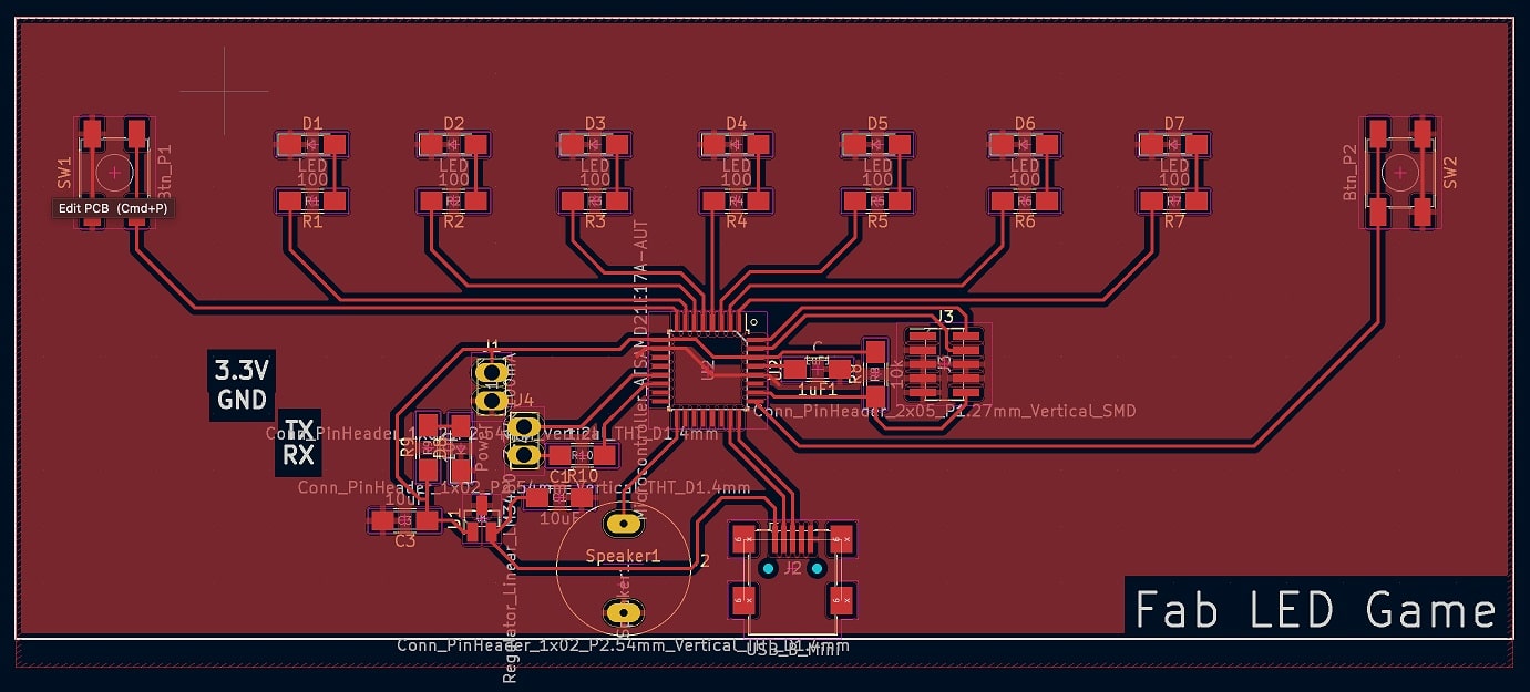
For milling, I used the same process that I used for my last two boards. So saving the SVG, going to Inkscape to export it as a PNG, alter the PNG with GIMP to achieve one image for the trace cuts and one for the cut out, and after this use mods to calculate the toolpath. In mods I quickly noticed that the pads for the chip were not calculated the way I wanted. They were all connected without cuts between them. To fix this, I went back to KiCAD and just altered the footprint of the Chip to have smaller pads, so that the tool could enter the space between. With this done, the pngs were done and the board ready to cut.
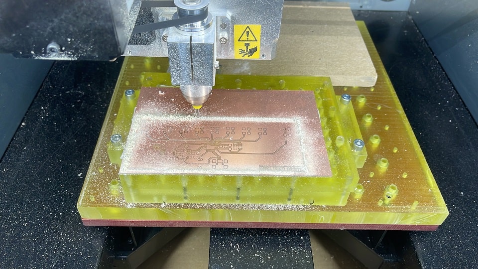
I zeroed all the axes, applied sticky tape to the board and placed the board on the sacrificial layer. This time I used a 0.4mm cylindrical bit for the traces. For the Cutout I once again used a 1mm bit. After cutting and drilling the Holes, the Board looked like this:
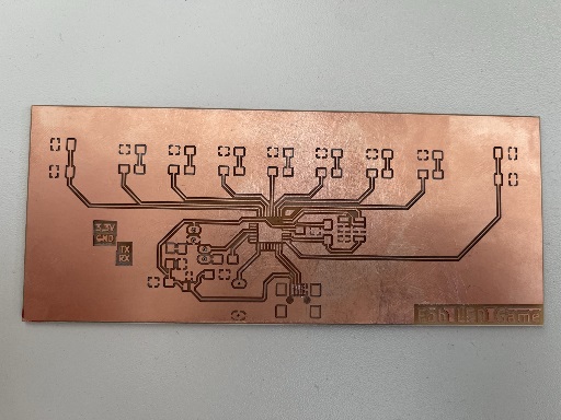
As you can see, everything looks very nice, but the connecting pads for the Mini USB port. As it turns out, I just was not paying enough attention when looking at the generated toolpath. I was so fixated on the pads of the microprocessor, that I oversaw, that the pads of the MiniUSB were also all connected to one another. To fix this, Ahmed showed me how to use our proxon drill free handedly. This is why the traces there look so ugly. In the end this will be covered by the port itself, but for the future the pads of the MiniUSB ports also have to be made smaller.
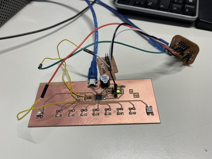
With the board done, I gathered all the materials for the Board according to my BOM, and began soldering. This turned out to be a very hard task. I had a very hard time soldering the components to the board. Many times the copper lines would just peel away from the layer beneath. This resulted in a very frustrating experience where I had thought that I broke the board on multiple occasions. With some jumper wireing however this was still all savagable. One of the bigger problems I had was the JTAG- connector, that is used to set up the microcontroller , so that it can be used via USB. I used the 2x05 connector footprint of the fab library. When trying to solder however, I noticed that our two by X connectors did not share the same footprint. Since the board was already milled, Ahmed suggested we just use wires to use the JTAG connector, since it only has to be used once. After that one can freely program the board through USB. This resulted in the following Image:
Following Quentins documentation, I downloaded the bootloader for the board here, and installed EDBG on my machine as detailed by Quentin here. With this step done, I connected everything as seen in the picture above and run the following command:
edbg -bpv -e -t samd11 -f sam_ba_Generic_x21E_SAMD21E17A.binTo my very surprise this just worked. Since one of the JTAG connection traces was already lifted up and only dangling on the wire, I for sure thought that I would have to mill a new board, but it worked! I was greated with the following message:
				Debugger: Alex Taradov Generic CMSIS-DAP Adapter ACF001FF v0.1 (S)
				Clock frequency: 16.0 Mhz
				Target: SAM D21E17A (Rev D)
				Erasing... Done.
				Programming... Done.
				Verification... Done.
Now the chip was ready for programming! To start uploading skecthes to the chip, I first had to gather the board informations. This is done under the preferences in the Arduino IDE. Here the user can add additional Board manager URLs. In my case the URL I had to had, can be found here. After adding the URL and installing the additional Boards I changed the settings under Tools like follows:
- Board: "MattairTech MT-D21E (rev A)"
- Microcontroller: "SAMD21E17A"
- Clock Source: "INTERNAL_OSCILLATOR"
- The rest was left stock
I changed all the pins for the program accordingly and tested it out. It first seemed to work, but after a short time I noticed that the interrupt for one of the buttons was not registering. After looking back into the interrupts of the SAMD21E17A, I could not find a cause for this behaviour. The two pins connected to the button should be handled seperately with external interrupts. Now comes the really bad part. I played around with the arduino settings, and wanted to try out Rev B in the board settings. I did not pay attention to the other settings, which when changing the board change back to standard. So I flashed with the wrong settings and after that the Board could not be recognized as a Port inside the IDE anymore. Since I am not at the lab until thursday, I sadly have to wait to check if I can just use the JTAG connector again, to reset the chip. As it stands now, I only have A board that features a power LED and nothing else. Will update here if I manage to repair the Board. For now I can only share the video of the breadboard version:
UPDATE:
After getting back to the lab and reflashing the SAMD21, I could finally send my program to the chip and make it work! With the standard Bootloader from the link further up, I could not use the pin I had designed to use for the button interrupt for player 1. This meant that I had to change the Bootloader. I scoured the Git repo and finally found the solution. This file here had to be changed in order to get pin 7 to register inetrrupts. After comparing The entry for pin 7 which I wanted to change and pin 27 which already worked the intended way with interrupts, I quickly noticed that I did not have to change much. In the end I just copied the codeline for pin 27 and just changed the pin number and the interrupt number accordingly. With this done inside the arduinos board library, I could just reupload my code and now it registered both interrupts; Neat!