
Assignment 14
Assignments
Individual Assignments
- design, build, and connect wired or wireless node(s) with network or bus addresses
Group Assignments
- Send a Message between two projects
Group Assignment
As im alone in Kamp-Lintfort from now on, I tried to come up with an Individual Assignment that doubles as a Group Assignment! Below you can read how I let two of my previous projects communicate with one another!
Individual Assignment(s)
For this week (and in part also for next weeks assignment), I wanted to realize a small project which I wanted to do for quite some time now. I wanted to visualize the current position of an in orbit object like the international space station (ISS) on a two dimensional map. Since I knew, that the current position of such objects could be gathered via specific APIs, I knew I would need some kind of wireless connectivity to gather the data and let one of my boards use it. Since I wanted to test out multiple connection systems at the same time, I came up with an Idea that would utilize network communication aswell as I2C communication at the same time. With this I would be able to learn how these tow different communication protocols worked and if it is even possible to use them like I want to :)
For now, the plan looked like follows:
- To gather the positional data through periodic API calls, I wanted to use an ESP8266 Module
- This data would then be read by one of my own Boards via Serial connection
- The data would then be sent to one of my other Boards via I2C
- Finally, the second Board would publish the data on a serial port to a python program, visualizing the current position on a map
As I was confused one or two times myself, I made a small picture to show what my plan looked like:
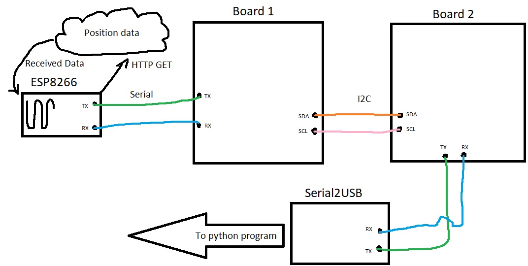
As you can see, the plan looks not very complicated. However, I definetly did have my fair share of problems with this assignment. The most important thing to notice for now is, that TX and RX are not swapped for the ESP to Board 1 connection. This is not mistake, but rather intentional as the ESP module swaps them itself according to the datasheet. With this plan, I then created smaller working packages to do one after another. These were:
- Getting an ESP8266, connect it to my Wifi at home and let it periodically request the ISS' positional data, sending it out via Serial
- Creating a sketch that reads incoming Serial messages and sends them along further through I2C
- Creating a sketch, that reads the I2C line and writes it to the Serial port on the PC
- Creating a python project, that reads the incoming serial Data and uses it to showcase the ISS' currecnt position on a two dimensional map
As interface programming is part of next weeks assignment, I will disregard the last point for this documentation, as I am going to build this program next week. Later on the documentation about this program can (hopefully) be found here.
I then began working on the first Goal: Getting an ESP8266 and make it gather data through API calls. For this I bought this kit online, since I could not make it to the lab due to some personal stuff, forcing me to stay at home. After receiving the Modules, I noticed, that I would need a sodlering iron to attach the power boards that came with the set. Reading through the datasheet beforehand, I knew, that the chip would only take an input voltage of 3.3V, stating that higher Voltages could and possibly will damage the Board/Chip. I scoured my home for an alternative and in the end just used an Arduino Uno as some sort of power delivery with its 3.3V Output, well aware that the Amps could possibly not be enough to drive the ESP8266. But I wanted to try it at least. Following multiple tutorials and even an eBook that came with the Modules, I struggled for a few Hours to get the ESP8266 to work at all. In order to program it, I connected it according to this tutorial I found online. No matter what I did, however, the Arduino IDE did not seem to be able to connect to the ESP8266 in order to program it. I was majorly confused and scoured the web to find solutions. What surprised me the most, is that the serial communication, without uploading a sketch, worked fine. I could send AT commands without a single problem. The error I got when uploading sketches from however was the following:
esptool.FatalError: Failed to connect to ESP8266: Invalid head of packet (0xF0)
After searching online, the problem was fixed with so many different solutions for different people,
that I did not know what my problem was. No matter what I tried, I just was not able to get the IDE
to program the ESP8266. This is, until I found out (the hard way -scouring the web for hours-), that
the ESP8266 is best used with two buttons to control its internal modes. A classic reset button as
well as a "program" button. Since I only was able to use breadboards at home, this would not be the
most beutiful solution, but it could solve my problem. Just so other people do not make the same
mistake, this Beginners
Guide to the ESP8266 helped me soooo much. I can fully recommend it! With the ESP connected
the way the Guide shows, I tried to upload the sketch once more, this time setting the ESP into
programming mode first, through the use of the two buttons. One can chek if the ESP is in
programming Mode by listening to Serial on the port of the ESP with a Baudrate of 74880. This is the
ESPs Debug Baudrate. If reset correctly the ESP will display somethin along the line of
boot mode: (x, y). If x is equal to 1, then the ESP is in program Mode. If its equal to
three its in normal mode. With this one can quickly check if the reset circuitry functions correctly
and if the ESP is ready to be programmed. To my dissapointment it still did not
work. Sometimes the error code was the one above, sometimes it told me that the serial port could
not be found at all, sometimes it said in the beginning, it was looking for port "COM4" and in the
error MEssage below it said no device found on port "COM _". After almost giving up completly, I
tried one last thing. Instead of using the
Arduino UNO, I used my CatISP to program the chip. I just let the Arduino deliver power to the chip
and let the CatISP handle the communication, since the CatISP only would deliver 5V instead of the
needed 3.3V for the ESP. And for the first time I could finally upload a sketch
to the ESP8266. I still dont know why I was not able to do it with my Arduino UNO, but I was more
thatn happy that after all these hours of troubleshooting, I was finally able to uplaod a simpe,
blink sketch I found online, which made the LED on the ESP8266 Board blink.
After that I searched for libraries and methods to generate API calls and receive data with the ESP8266 and found solutions very very quickly. I just edited one of the API call examples I found, added JSON functionality to it, in order to deserialize the data I would need and ignore all of the unneeded data to build the string I would be transmitting. The whole flashing process and the chip receiving data periodically can be seen in this short video:
The code used to program the ESP is the following:
#include <ESP8266WiFi.h> //Needed for the ESP8266
#include <Arduino_JSON.h> //Needed since API goves out JSON
#include <ESP8266HTTPClient.h> //Needed for the ESP8266
#include <WiFiClient.h> //Needed for the ESP8266

#define SSID "xxxxxxxx" //SSID that the ESP8266 will be trying to connect to
#define PASSWORD "yyyyyyyyyyyyyyyy" //Password for the corresponding SSID

const char* serverName = "http://api.open-notify.org/iss-now.json"; //The server that I want to gather data from

int APITime = 2500; //"Cooldown" between API calls

String APIValues = ""; //Raw JSON data

String positionData = ""; //Deserialized positional data

void setup()
{
	Serial.begin(115200); //Begin Serial connection

	WiFi.mode(WIFI_STA); //Use the ESP as a Station and not as an Access point
	WiFi.begin(SSID, PASSWORD); //begin connection with given SSID and PW

	while(WiFi.status() != WL_CONNECTED) { //While not connected to the SSID
		delay(1000); //Wait
	}
}

void loop()
{
	if(WiFi.status() == WL_CONNECTED){ //if the Wifi is connected

		APIValues = httpGETRequest(serverName); //Request Data from the server
		JSONVar obj = JSON.parse(APIValues); //Parse the data as JSON
		positionData = ""; //Reset the position data
		if (JSON.typeof(obj) == "undefined") { //If JSON object is undefined
			return; //stop this cycle
		}
		//Build Position Data String
		positionData = "{";
		positionData += JSON.stringify(obj["iss_position"]["latitude"]); //From reading the API, I gathered the keys to access the data I needed
		positionData += ","; //Comma seperate the two values
		positionData += JSON.stringify(obj["iss_position"]["longitude"]);
		positionData += "}";
		//Send the data
		Serial.println(positionData);
	}

	delay(APITime); //delay between now and next API call
}

String httpGETRequest(const char* serverName) { //Method that returns a String, when given an adress using http GET
	WiFiClient client; //Generate client Object
	HTTPClient http; //generate http object

	http.begin(client, serverName); //Give the http object the wifi client and the server adress
	int httpResponseCode = http.GET(); //send GET request to the server, which will return a response code
	String payload = "{}"; //Generate a string to hold the data later on

	if (httpResponseCode>0) { //If the http response code is not 0
		payload = http.getString(); //get string gathered from GET request
	}
	else {
		payload = ""; //else String is empty
	}

	http.end(); //end connection
	return payload; //return string
}
With this step working after so many hours of troubleshooting uploading sketches to the ESP8266 I
sadly got a little bit ahead of myself. I quickly wrote the two remaining scripts and connected
everything the way I thought it would need to be connected. All of this only to be majorly let down,
because of course nothing came through to the end. The biggest problem now was, that I had no tools
whatsoever to troubleshoot where the data was being lost, as I could not read the RX/TX from the
first Board, as it was used to receive the data form the ESP8266. After some time thinking, I went
ahead and tried to get an I2C connection up and running, just between the two Boards in the middle
of the plan from above. I wrote two simple scripts using the Wire.h library. I configured one Board
as master, sending out messages to a specific adress every three seconds. On the other Hand I had
the slave board, where I configured the Adress used in the master sketch via the
Wire.begin(adress) command. After a little bit of troubleshooting and stupidity on my
side, where I have connected the pins from the master board to the wrong ports on the slave (I
reused a Board that was not done for this purpose, so I was confused translating between the SDA/SCL
pin numbers and the pin functions I had previously designed for this Board on those pins), I could
read out the dots, the master was sending to the slave
every three seconds! Knowing that the pure connection was working now, I reassembled everything and
hoped for the best. If I was able to read out the ISS' current position on the slave Board,
everything was working as intended. The whole structure looked like this in the end:
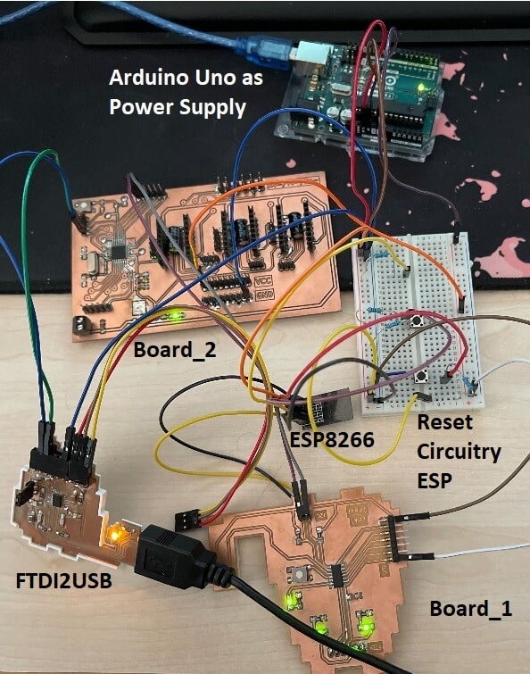
As you can see this is beyond messy and really not ideal. But it is a proof of concept and would be much cleaner with one of these esp8266 programmers. THen the whole Breadboard could be eliminated from the picture. Also a normal power delivery would be nice. I have a breadboard power source at home, but sadly not the correct plug to plug it into the wall.
Apart from this very big mess, I was very tempted to finally take a look at the serial Monitor to look if the data found its way through this mess. At first nothing came up. But I had this problem many times and just restarted the Serial Monitor. And to my great surprise - FINALLY - somethin came up on the serial Monitor. And even somethin legible! Sadly not completely what I wanted however:
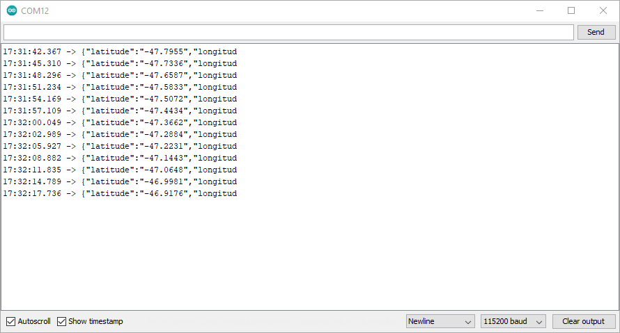
As you can see, the data is cut off at a specific value for each data packet. While this was quite frustrating in and of itself, I finally got what I had planned before!! Just not compeletly :D
And so I went ahead and searched for the error that was causing this. The error was quickly found. Since each character that is being submitted over I2C takes up one byte, and the standard I2C message is a maximum of 32 Bytes long, only 32 characters could be passed along at a time. Now there were multiple solutions possible for this error:
- 1) Change the maimum Bufersize within the Wire.h library
- 2) Split up the message in to two parts
- 3) Shorten the message to fit within the 32 Byte limit
After thinking about it, I chose to go with the third sollution. I did not chose to change the
library, as I did not want to fiddle around with standard libraries too much, as to not break more
than i wanted to fix in the first palce. I also did not go with the second options, as there were
many characters that were simply not needed at all within the messages. It does not make sense to
send the words "latitude" and "longitude" with every message. Since the API and therefore the JSON
have a set order of elements, I knew that latitude would always be the first of the two values. This
meant, that there was just no need fot these characters, I just needed to send over the raw values.
The maximum amount of characters that could be generated through the API calls was now 9 bytes for
each numeric value, as well as 7 bytes of spacing and seperation characters. This meant that the
maximum number of bytes to send was now 26. The message would then look like this:
{"-xxx.xxxx","-yyy.yyyy"}. After reading out the raw values from the JSON, I created
my
own string, and built it like shown before. With this change, the I2C connection sould no longer be
bottlenecking the whole connection line from the ESP to my FTDI to USB Board. After plugging
everything back in, I got the following:

In the end, the code for both Board looks like follows:
Board 1, my Big Cat Board, using an ATtiny1614:
#include <Wire.h> //Needed for I2C
#define I2CAddress 12 //I2C Adress of the second Board (Fully customizable when using 328p as second Board)
#define led 10 //Pin to the onboard LED on the Board for debugging

String text; //text to be sent to the second Board

void setup() {
	Serial.begin(115200); //Begin Serial transmission (115200 because ESP uses it)
	pinMode(led, OUTPUT); //Set LED pin as Output
	Wire.begin(); //Start the I2C connection
}

void loop() {
	text = ""; //Reset text
	while(text.length() == 0) { //If there is no text yet, try to get text
		getText(); //Method to gather data from the ESP
		digitalWrite(led, LOW); //While gathering data, LED off
	}
	if(text.length() > 0) { //If we have gathered data
		digitalWrite(led, HIGH); //turn on LED while sending
		sendText();
	}
}

void getText(){
	if(Serial.available()) // Check if there is data available via Serial
	{
	while(Serial.available()) //While data is Available, do:
	{
		char c = Serial.read(); //read the next available character
		text += c; //Add the character read to the string, to collect the whole string
		delay(10); //delay for a short amount of time
	}
	}
}

void sendText() {
	Wire.beginTransmission(I2CAddress); //transmit to the second Board using its I2C Adress
	for(int i=0; i<(text.length()); i++){ //Go through all characters of the string with a for loop
		Wire.write(text[i]); //Write the individual Scharacters
	}
	Wire.endTransmission(); //End the transmission if all characters are sent
}
Board 2, my Motor Driver Board, using an ATMega328p:
#include <Wire.h> //Needed for I2C Connection

#define I2CAddress 12 //Adress of this Node

void setup() {
	Serial.begin(115200);  //Begin Serial Connection
	Wire.begin(I2CAddress); //Begin I2C Connection, set up as device with Dress "I2CAdress" (In this case 12)
	Wire.onReceive(receiveString); //Function that calls another fucntion when data is being received via I2C
}

void loop() {
	delay(10); //Do nothing but delay in loop
}

void receiveString(int bytes) { //Method to recevie a string and send the receied data on via Serial
	String text = ""; //Clear the string
	while (Wire.available()) {  //While I2C has data vaiable for this adress
		char c = Wire.read(); //Read one character at a time
		text += c; //Add the character read to the string
	}
	Serial.println(text); //Print out the complete received String via Serial
}
Since now the ISS' current position was being transmitted over from the ESP8266 through Serial over I2C through Serial again, the next task would be to build a program that could read the incomming serial port and use this data to show the ISS' current position on a map. This is what I want to do next week!
As a last Bonus, I wanted to try and send data to another Node with I2C at the same time as I am
sending the data to the second Board. For this I used an OLED screen that was I2C compatible. To run
the OLED screen, I used a second Breaboard. I connected the 5V and GND pins to the Arduinos 5V and
GND Pins and used the SDA and SCL lanes of the Breadboard when the OLED is plugged in as sort of a
Bus, which means that Board 1 and Board two were both connected to SDA and SCL on the pins of the
OLED. I looked up the I2C Adress of the OLED, which turned out to be 0x3c or 60 in decimal (the
adress of my particular model could even be changed by changing the placement of a resistor on the
bakside of the panel, in case one wants to run two of these panels). I opened up the sketch for
Board 1, and searched for a short tutorial on how to send messages to these OLED panels. After a bit
of reading I got to work on the sketch. First of all I added the SSD1306Ascii library via the
library manager and included SSD1306Ascii.h as well as SSD1306AsciiWire.h.
I defined the OLEDs adress as 60 and set up a SSD1306AsciiWire object. Just like with normal I2C I
set call the SSD1306AsciiWire Objects begin method in the setup section. I then set the Font via
setFont(). Now I needed to tell the object, to print what I wanted. At first I just
printed the whole String, received via the ESP8266. This resulted in the following behaviour:
As you can see, the message was too large to fit into one line, which is why I wanted to change up the string in order to make it fit. For this I copied the String I would gather from the ESP8266 to manipulate it. I manipulate it in a way to gather both numbers, but no other characters, as seperate strings. I then print the whole thing in a way to be able to easily read the coordinates. This resulted in the following outcome:
With this done, I managed to send data to two different devices on the same bus, which made me quite happy. In the end, using the OLED screen, the Code for my first Board, running on an ATtiny1614 looked like this:
#include <Wire.h> //Needed for I2C
#include "SSD1306Ascii.h" //Needed for the OLED screen
#include "SSD1306AsciiWire.h" //Needed for the OLED screen
#define I2CAddress 12 //I2C Adress of the second Board (Fully customizable when using 328p as second Board)
#define OLED 60 //I2C Adress of the OLED screen
#define led 10 //Pin to the onboard LED on the Board for debugging

SSD1306AsciiWire oled; //Object to later send data to the OLED through

String text; //text to be sent to the second Board

String oledText; //text to be sent to the OLED screen

void setup() {
	Serial.begin(115200); //Begin Serial transmission (115200 because ESP uses it)
	pinMode(led, OUTPUT); //Set LED pin as Output
	Wire.begin(); //Start the I2C connection
	oled.begin(&Adafruit128x64, OLED); //Start the OLED connection using the screen definiton and the I2C Adress
	oled.setFont(System5x7); //set font of screen
}

void loop() {
	text = ""; //Reset text
	oledText = ""; //Reset OLED text
	while(text.length() == 0) { //If there is no text yet, try to get text
		getText(); //Method to gather data from the ESP
		digitalWrite(led, LOW); //While gathering data, LED off
	}
	if(text.length() > 0) { //If we have gathered data
		digitalWrite(led, HIGH); //turn on LED while sending
		oledText = text; //copy text to oledtext for manipulation
		oled.clear(); //clear the OLED screen with the old data
		String text1 = oledText.substring(0, oledText.indexOf(',')); //data is parted with a comma, so get first string up until comma
		text1 = text1.substring(text1.indexOf('"') + 1, text1.lastIndexOf('"')); //data is between two "; So find first and last Index to get number only
		String text2 = oledText.substring(oledText.indexOf(',') + 1); //same as text1, only that I want everything after the comma
		text2 = text2.substring(text2.indexOf('"') + 1, text2.lastIndexOf('"')); //same as text1
		//Print stuff on the oled screen
		oled.println("Lat: ");
		oled.println(text1);
		oled.println("---------------");
		oled.println("Lon: ");
		oled.println(text2);
		//send text to second Board
		sendText();
	}
}

void getText(){
	if(Serial.available()) // Check if there is data available via Serial
	{
	while(Serial.available()) //While data is Available, do:
	{
		char c = Serial.read(); //read the next available character
		text += c; //Add the character read to the string, to collect the whole string
		delay(10); //delay for a short amount of time
	}
	}
}

void sendText() {
	Wire.beginTransmission(I2CAddress); //transmit to the second Board using its I2C Adress
	for(int i=0; i<(text.length()); i++){ //Go through all characters of the string with a for loop
		Wire.write(text[i]); //Write the individual Scharacters
	}
	Wire.endTransmission(); //End the transmission if all characters are sent
}
In the end I am really happy with this weeks assignment. I managed to do what I wanted and learn many things about the ESP8266 and I2C connections. While this particular setup really does not make much sense, as the first Board could already function as Bridge for the ESP to sent data to a python program, I really wanted to see if I would be able to send data through different means and get something legible in the end, which worked out in the end!