4. Computer controlled cutting
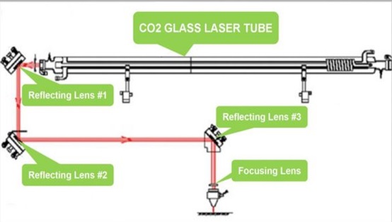
Team work The laser of the CO2 laser cutting machine is a molecular laser. The main gas working in the laser is carbon dioxide and the auxiliary gas is nitrogen, xenon and hydrogen. The ratio of the three gases and the total pressure can be changed within a certain range, generally CO2: N2: He = 1: 0.5: 2.5. And the total pressure is 1066.58 pa. The core of the CO2 laser cutting machine uses the transition between vibration and rotation energy levels of CO2 molecules to generate laser light. The wavelength of the laser beam in a carbon dioxide laser is in the infrared part of the spectrum, which is invisible to the human eye. The laser beam is emitted from the beam channel of the laser resonator that manufactures the beam and is 3-4 inches in diameter. The reflector of the CO2 laser cutting machine can reflect the beam in different directions. The laser beam passes through the nozzle to be focused together to form a higher energy, which is enough to achieve the cut.
Triplay
The pattern was drawn in AutoCAD to determine the cutting power and cutting power, for cutting a power of 50 and 10 speed was considered and for the tracing of letters a power of 20% and 20 mm/s speed where it we save in DXF format.
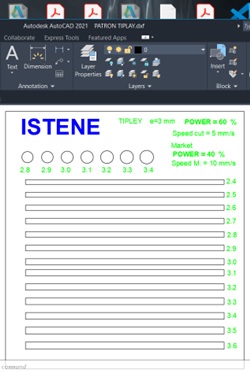
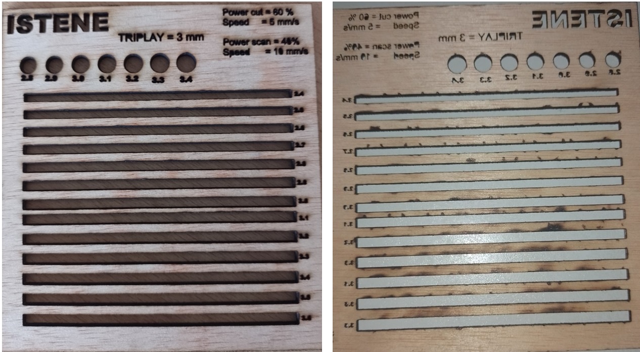
Then we open it with CNC laser to configure it with the laser cutter where we import it, but it does not recognize the letters so we have to edit the letters in the same program making a new layer, which we use to write the letters, we configure it with SCAN and the other as CUT where you set the power and speed. Where the first configuration for plywood of 3 mm thickness is configured cutting power at 60% and cutting speed at 5 mm/s, and engraving power at 40% with a speed of 10 mm/s where it can be seen that the cut is not a problem, but for the letters they were also cut, that means that the marking power is very high, or the speed is very low.
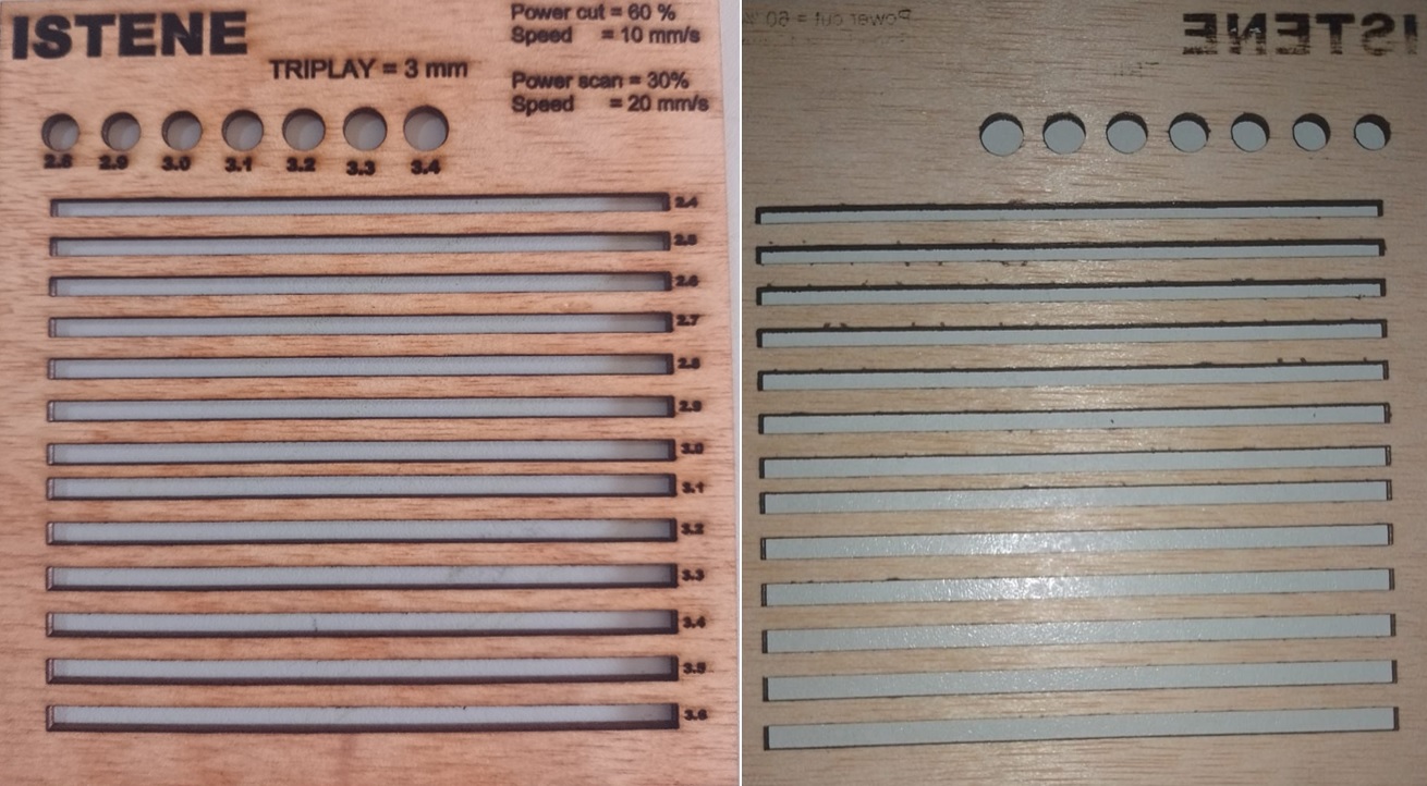
we make a second configuration where the cutting power is kept at 60% and we change the speed to 10 mm/s, where we can see that the configuration is still cutting, but the engraving power is still not adequate since there are still parts of the letters that have been cut.
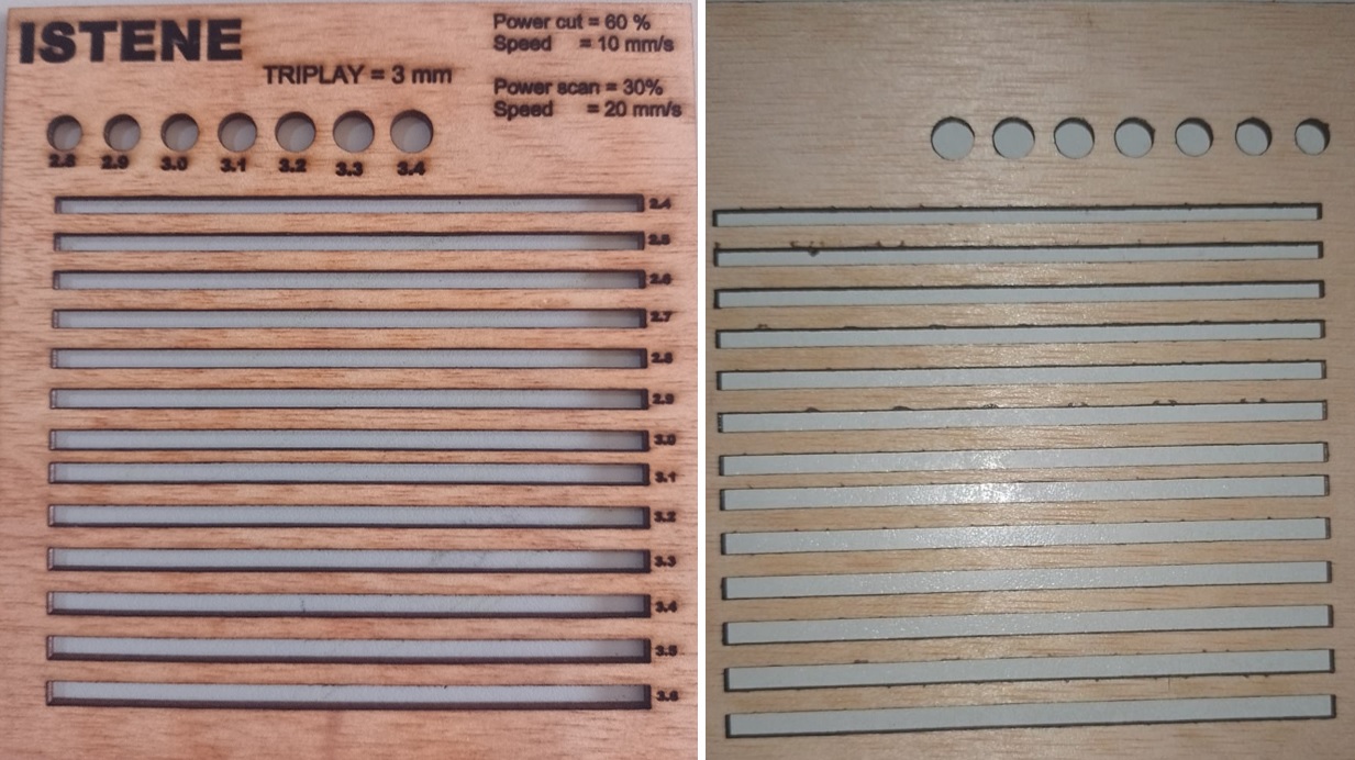
A third setting has been made to achieve that the engraving power and speed do not cut the material, so the new setting for the cutting power is 60% with a speed of 10mm/s and the engraving power is 20% and the speed 20 mm/s where the cut is cleaner than the previous ones, and the letters, the engraving is correct, it has not penetrated the other side.
Paperboard
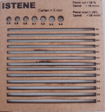
A cardboard pattern was prepared in the same way, which was configured with a cutting power of 50% and a cutting speed of 10 mm/s and for engraving with a power of 20% and a speed of 20, giving an optimal result without passing through the cardboard in the process
Acrylic
With the same configuration, the pattern for 3 mm thick acrylic is prepared, for which we make a cutting power configuration of 80% and a speed of 5 mm/s and for pomegranate with an engraving power of 20% and a speed of of 20 mm/s, that acrylic has good cutting and engraving quality as well.

Some comb-type patterns were also made, to be able to fit the parts in different sizes.

We made the fit between the different slots and it was able to fit.
I would have liked to experiment with more materials, but we lacked time and materials.
This week I worked on defining my final project idea and started to getting used to the documentation process.
VINYL CUTTER
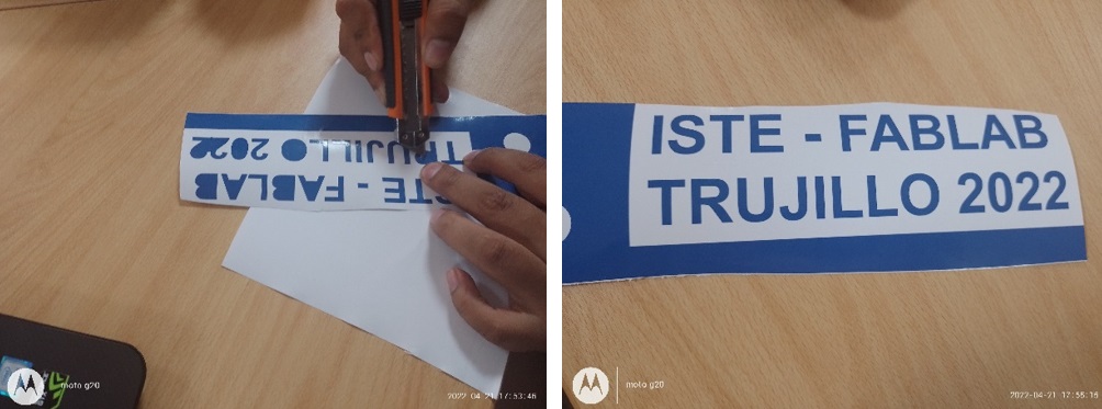
To cut with the vinyl cutter, I first had to vectorize the institute shield with the cut studio software.

Then you have to place the vinyl on the cutter, leveling and censing the starting point to then give the order to start cutting.

Then you have to take off the part that is not of interest, with the cutter tool, take off slowly so as not to take off what is of value.
Then, to unstick the letters, you have to do it with a masking quotation, you have to press well to achieve a uniform bond with the quotation and then unstick it very carefully so that the letter remains uniform.
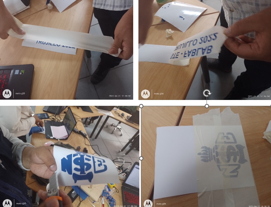
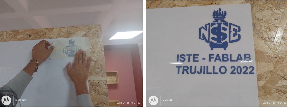
To then take the surface where it is going to be placed, which must be smooth and free of dust, where we must apply enough pressure with our hands on the entire surface where the letters go, and then carefully remove the masking tape without lifting the letters
LASER CUT
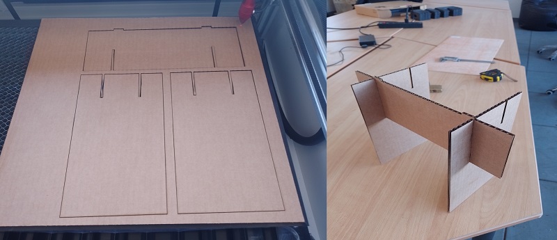
I made the sketch of the parts of a table that will be assembled by pressure joint in inventor version 2021, for which I made a 2D parametric drawing based on the thickness of the material, these restrictions start from one side with 300 mm with the parameter (Width= slot*50).
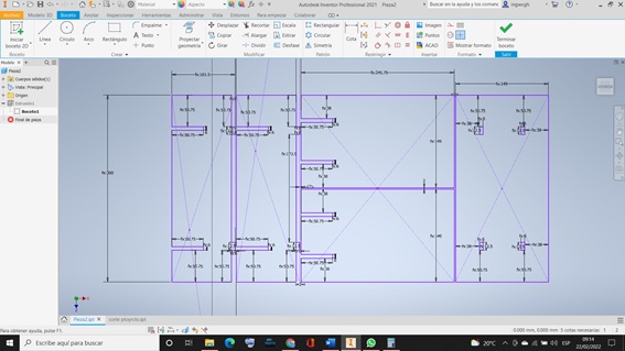
Then, when I extrude to give the thickness to the material, in the part of adding the thickness, I put it according to the slot, which is 6 millimeters.

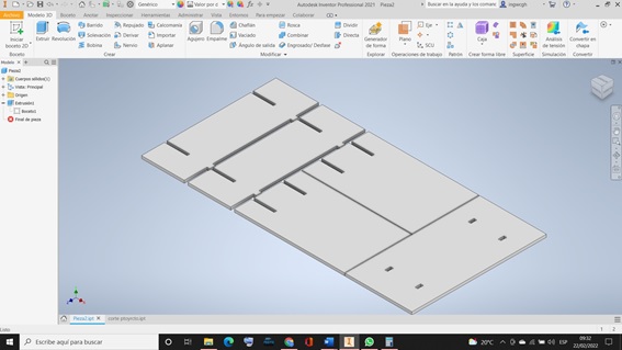
Remaining the cut shapes for each of the parts of the table.
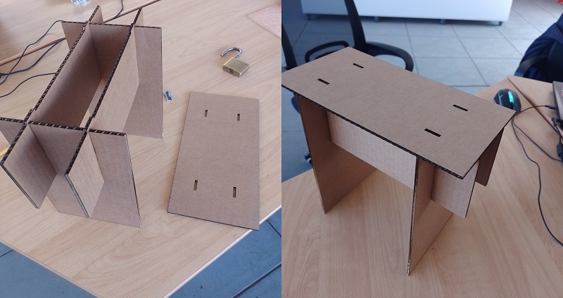
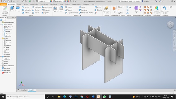
Then the assembly of each of the parts that make up the table is carried out

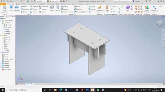
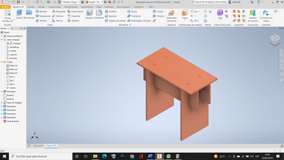
After the design is passed to the CNC laser software to give the correct cutting parameters for cardboard, where the cutting power is 50% and the speed is 10 mm/s, which has obtained a precise cut that we then join by fitting, leaving the table assembled correctly.