3. Computer Aided design
There is a great diversity of computer aided design programs, my beginnings were with Autocad in which I use to draw 2D parts, with inventor model 3D parts, where I can also simulate the efforts to which the exposed part is, fusion It is a program that I have recently started to use and I find it very interesting.
Autocad 2021
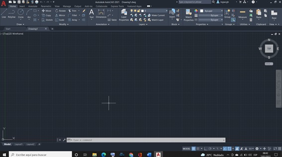
To start the 2D drawing I am going to use Autocad 2021, software that I have installed on my computer, to start working with Autocad, we must start by clicking on the program icon, once it is open it shows us a window with command icons and a black area to draw, where we can find, list with interactive icons such as drawing, modify that are the most used list for the work of drawing in 2D.
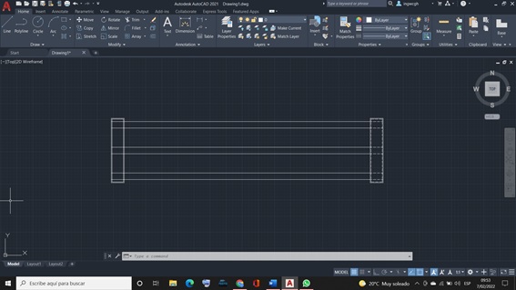
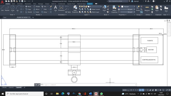
I am clicking on the line command, and I start drawing the plan view of a device that consists of 2 rails and a threaded axis in the center with two rectangles that represent the bases of the device, also when we finish the drawing we have to dimension the drawing of plan view, where we can observe a culminated device, its platform that will have a longitudinal movement, the control box is also shown.
Drawing the cutting system of the device plan view
Fusion 360
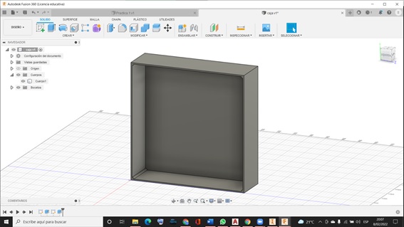
Using Fusion 360, the project box has been modeled, which will house the motor, power supply, PIC controller.
Inventor 2021
To draw in 3D I am going to use the Inventor 2021 program, the entry is similar to that of Autocad, using the icon with the letter “I”, this does not open a window where you have to configure the unit in which you are going to work, to which starts with a 2D drawing, applying the command from the drawing list and the modify list, and then applying the command from the modify list. In inventor, each of the parts has to be drawn in 2D by applying the commands from the drawing list, modify and Shorten, when the modeling of the part in 2D is finished, then we carry out accept and our drawing is put in perspective, and then we carry out extrude where given thickness, you can also give length once finished, we save.
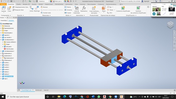
Once our parts are drawn in inventor, we assemble, for which we pull each of the parts of the machine stored on our hard drive, once we see all the parts on the screen, we fix one and then with restrictions it is assembled.
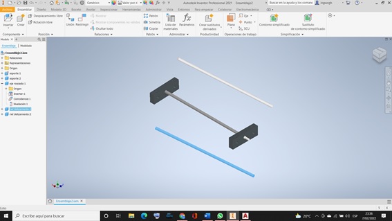
Slide shafts and worm screw assembled.
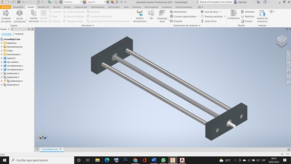
The slide rails were assembled, as well as the threaded shaft and its respective nut.
performing slip
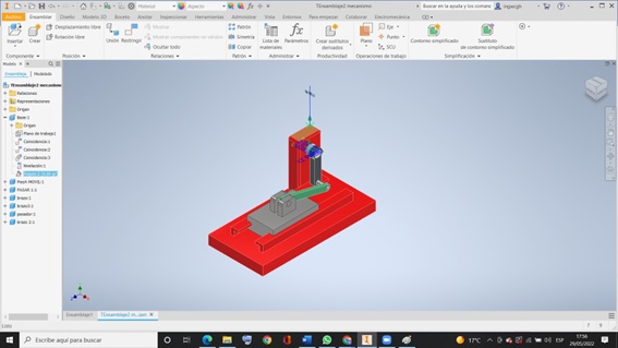
Circular motion to linear motion mechanism
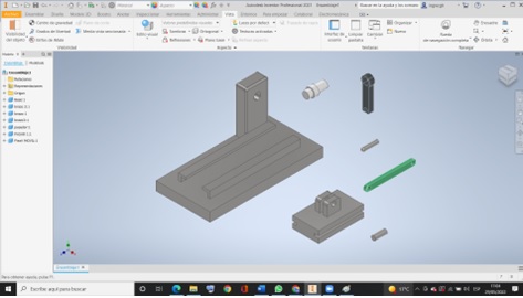
I am going to model a mechanism that has a circular movement to a linear movement, I will do this modeling in inventor 2021, to start the modeling we must start by modeling each of the parts of the mechanism that is made up of 7 parts that must later be assembled.
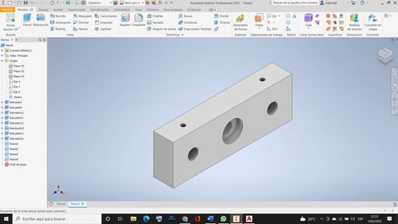
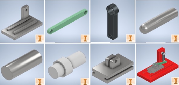
Part modeling
Where I started modeling the base, 12 cm wide by 25 cm and 12 mm thick, with 20 cm sliding rails - The green horizontal arm has been modeled with a length of 10 cm with two holes, one 10 mm and the other 8 mm. - The black vertical arm has been modeled with two holes, one to be assembled on the motor base and the other hole for the sleeve which will support the horizontal arm. - The 10 mm diameter pin that will be assembled on the slider with the horizontal arm to give the linear movement - The drive shaft with 15 mm diameter is responsible for supporting the vertical arm and also giving movement to the system. - The slider with a length of 10 cm in length and 80 in width, checks the linear movement that is generated by the motor arms.
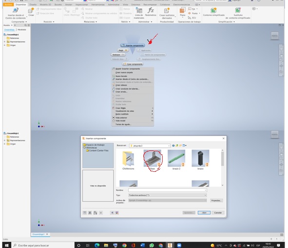
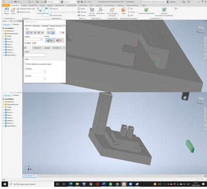
Assembly of parts To assemble you have to start with inventor’s assembly then on the screen you have to right click to insert component, for which we select the base from the folder where the parts are saved.
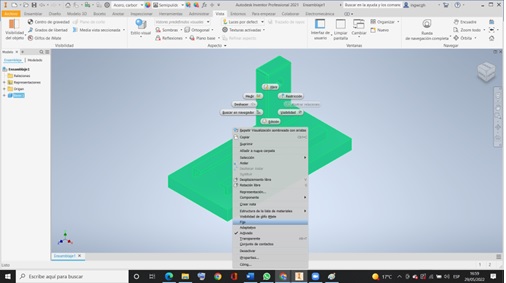
Firstly, we select the first image, for which we must fix the image in a view that is visible to be able to assemble the other components, for them you have to right click and select “Fixed”
Then you have to select the rest of the images to assemble them one by one by right clicking and select them all
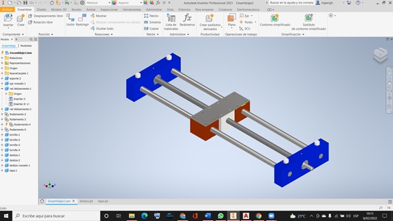
Start by assembling the slider so click on the constrain option. First I click on the slider face and then on the base and slider face and then on one of the faces of the side of the slider with side face of the rails and the slider will snap flush to the rail.
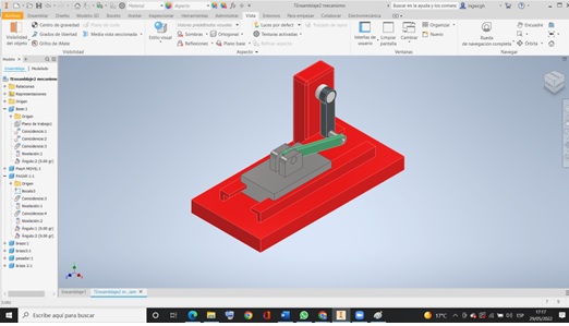
And so on, the other parts were assembled until the entire machine was assembled ready to move.
dynamic simulation
To give movement to the motor axis 360° on its axis which will rotate the vertical arm and at the same time the horizontal arm, making the slider acquire a circular movement. To achieve this you first have to constrain the drive shaft planes to the vertical arm plane, aligning them at zero degrees.
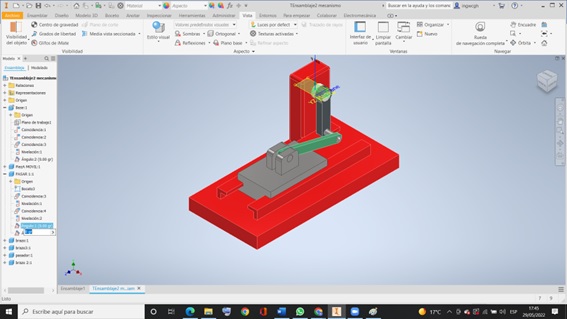
Once the axes are aligned, we go to the left where the list of all the operations carried out is presented, we perform angle restriction by clicking on the base of the support, then we select the floor plan of the axis and then on the support where the first click and you are ready to simulate.
Once the axes are aligned, we go to the left where the list of all the operations carried out is presented, we perform angle restriction by clicking on the base of the support, then we select the floor plan of the axis and then on the support where the first click and you are ready to simulate.
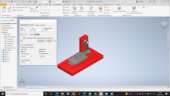
Then we press the start button, it starts the movement of the mechanism, which we can also increase the speeds.