3. Computer Aided design
Modeling on 2D
This week I worked on defining my final project idea and started to getting used to the documentation process.
Inkscape: Software that allows you to vectorize graphics and improve their quality, can be used by professional and amateur designers. I did not know the software is new to me, it is very easy to work with and educational.
Support me with a video on YouTube:
-
Inkscape it helped me a lot to use some commands.
-
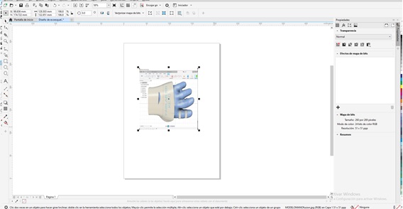
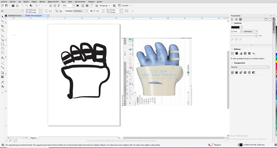
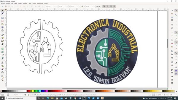
Select a referential Image: Logo of the study program of Industrial Electronics of the IES “SB”.

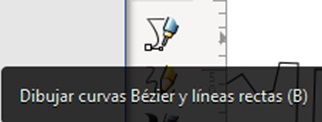
- Use the tool to draw Bézier curves and straight lines.
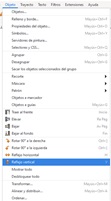
- To copy: First select the image then right click select copy
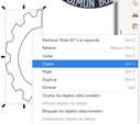
- Apply vertical symmetry: Go to objects file then go horizontal reflection
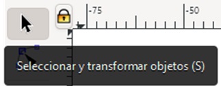
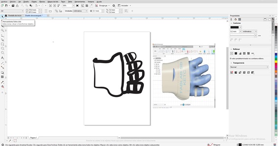
- Group:: First step: Select and transform objects
- Then right mouse click select group
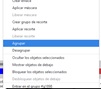
Using CorelDRAW 2019
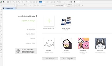
- Select and click on new document – Complete data
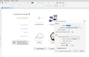
- then click ok
Now to start designing:
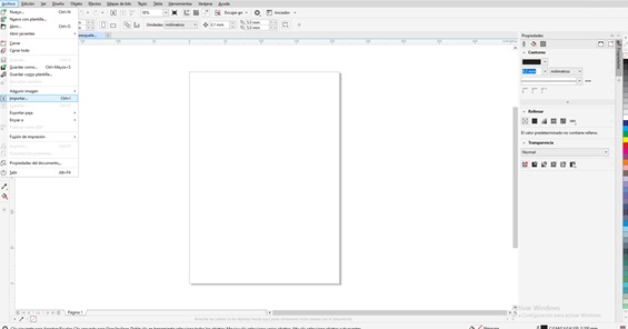
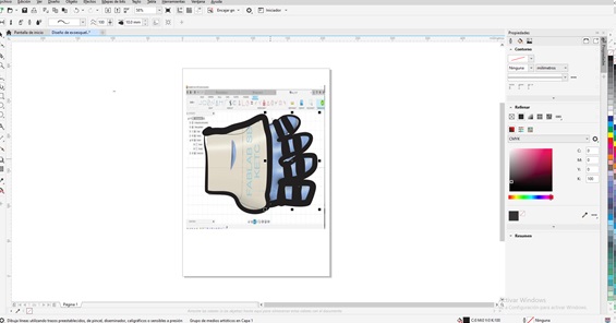
- Click file browse import - click, then browse image to import
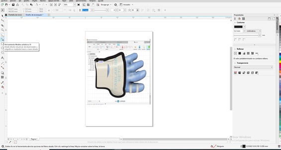
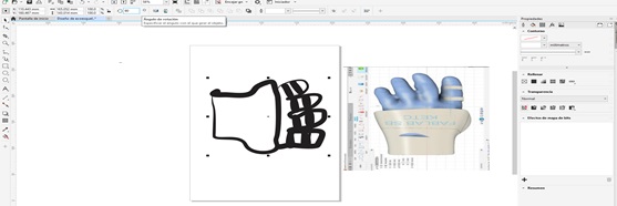
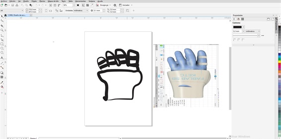
- Use artistic media tool, border the hand without considering the fingers
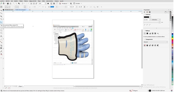
- Freehand tool, to make the edges of the fingers of the hand
- To reduce or enlarge the design you must rotate the middle mouse button
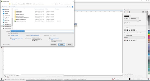
- To save the changes click on the figure of a diskette or Ctrl + S, then specify the location or path to save the design
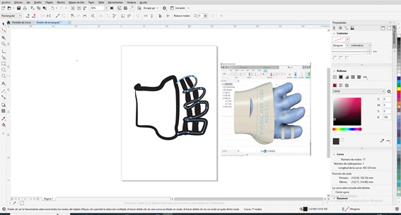
- To improve the contour click on the nodes
- Then just to select
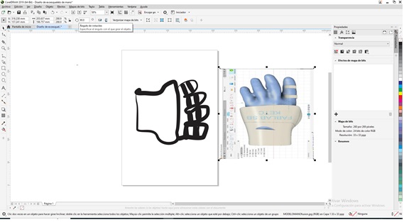
- To rotate the image click and specify the angle of rotation
- To select all the images you must left click and drag until you select everything you want, then click and specify the angle of rotation.
In my opinion, designing in 2D with Inkscape made it easier for me to work with respect to CorelDraw. In addition, I have to add that working with unlicensed programs allows us to contribute to their improvements, in the case of Inkscape.
Useful links
-
Inkscape it helped me a lot to use some commands.
-
[Inkscape]

-
[Inkscape]

-
Work done
Modeling on 3D
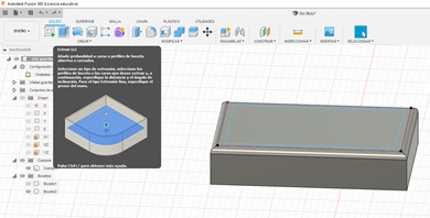
Working Fusion360 – Probable Final Project
Fusion360 is software from the Autodesk CAD, CAM family, it allows printed circuits to be made with 3D modeling based on the cloud for the design and manufacture of products, widely used by professionals and amateurs, it is very easy to use, its modeling begins with the 2D sketch creation to then build 3D solids. It is very interesting.
Fusion360: Software that allows you to vectorize graphics and improve their quality, can be used by professional and amateur designers. I did not know the software is new to me, it is very easy to work with and educational.
- Fusion360 You can download the free trial version, more information in the link.
Support me with a video on YouTube:
-
Fusion360 it helped me a lot to use some commands.
-
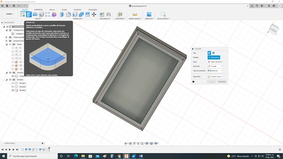
Fusion 360
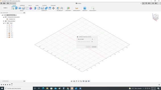
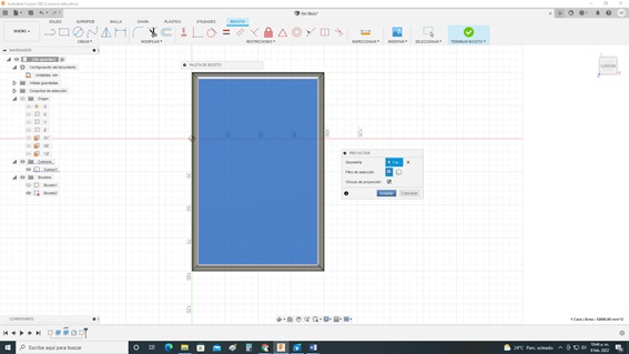
- Entering Autodesk Fusion360 Configure the units
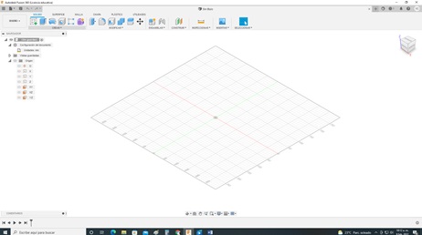
- Now select the plane to work
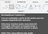
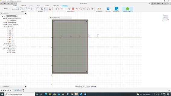
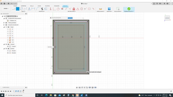
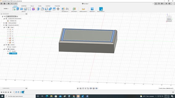
- On the sketch, create a rectangle with the following tool
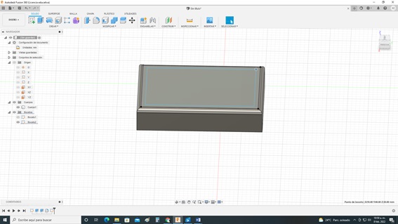
- With the extrude command a cube was generated
- With the Fillet command, the edges of the body of the solid were rounded.
- To configure the splice, select the edges and enter the required dimension
- The visualization of the changes applied by the splice
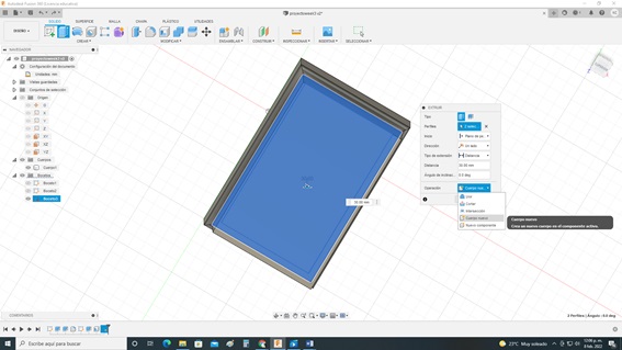
- NEW PLAN CREATE SKETCH: Select the body where the new body will be created
- Click on create a sketch
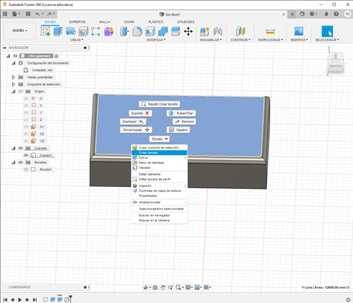
- THEN PROJECT Click create, the select project brings up a dialog box
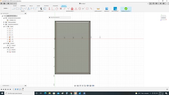
- On the sketch, create a rectangle with the following tool
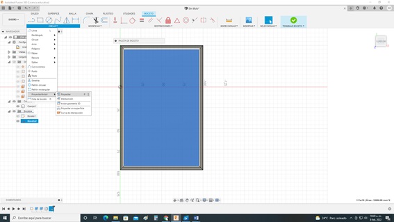
- CLICK PROJECT
- Result of projecting
- I generate two rectangles
- Finish Sketch
- Use the exclude command to
- Then select the excluded área
- Specify the distance to exclude
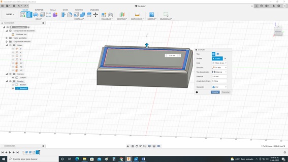
- The result of excluding
- Apply the dump command
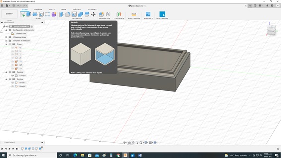
- Select shell area, specify interior thickness
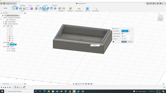
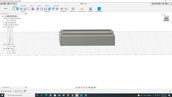
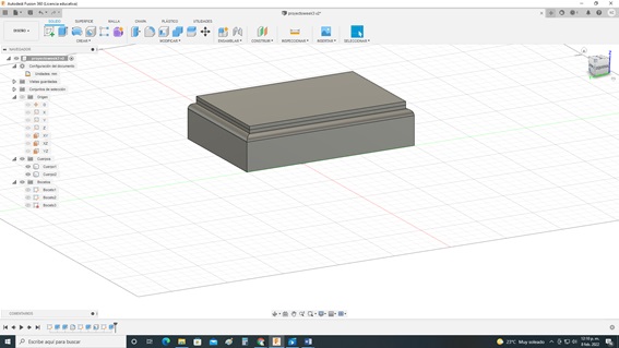
- To create the lid Create new sketch
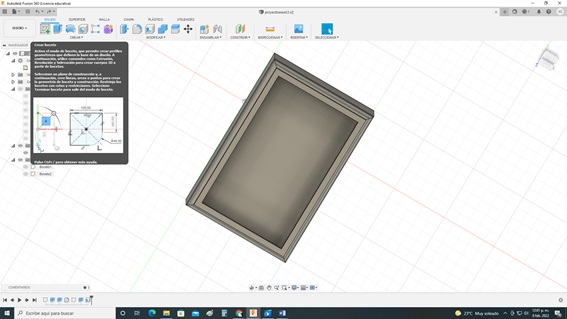
- Go to create, select project
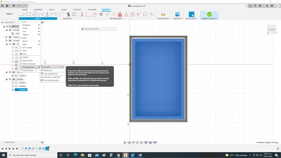
- Click exclude
- Specify the dimensions later, in this case, as a lid is being prepared, the operation to select is a new body
- Then click accept
- Create body components1
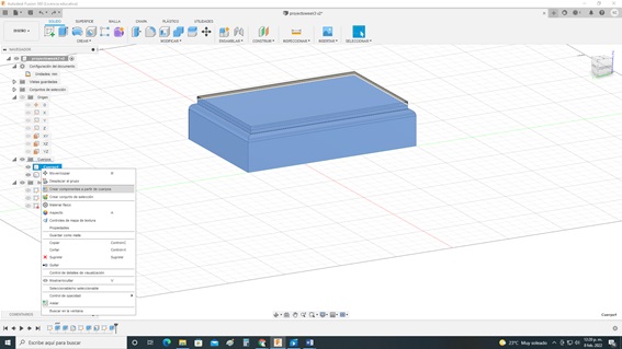
- Create body components2
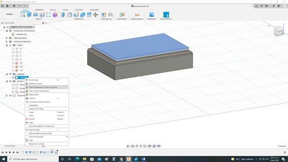
- Click on union
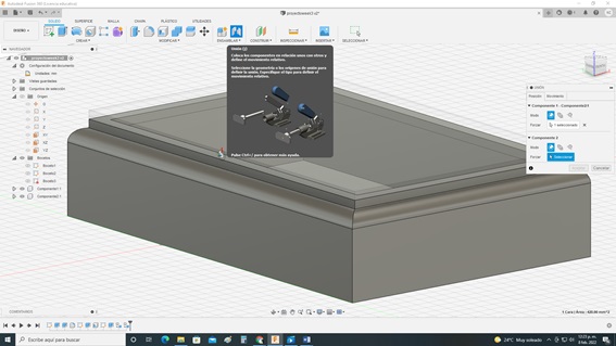
- for body movement Click on assemble union
- Component Motion Effects
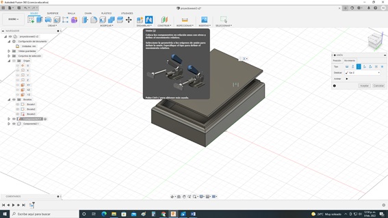
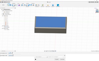
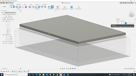
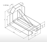
- Progress of the final project
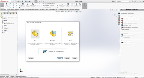
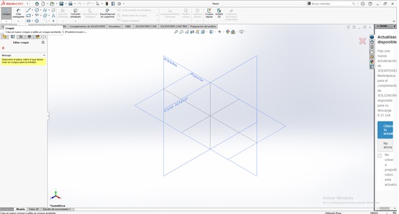
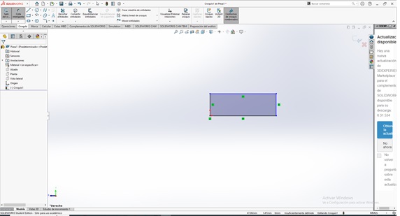
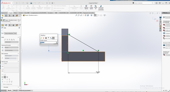
Design in SOLIDWORKS
- Design to build1
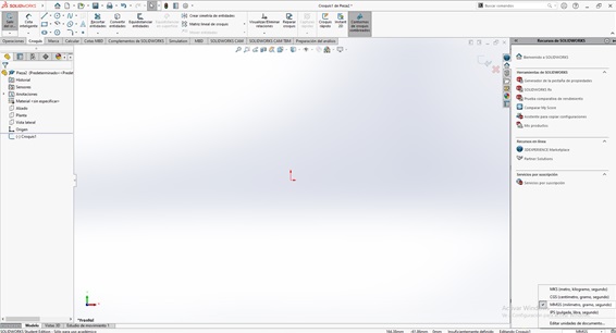
- Click on new document, select part and accept
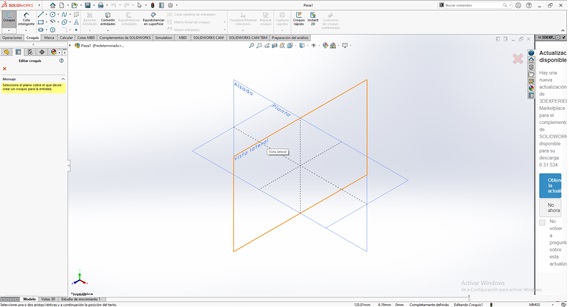
- Click on the sketch file then select sketch
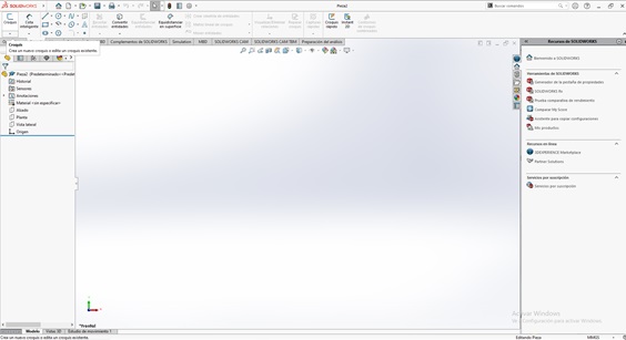
- Then select elevation (First quadrant)
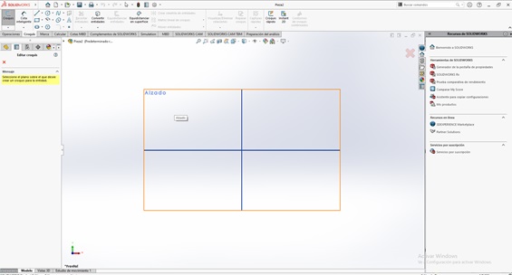
- Then verify the measurement unit system to be used in our case MMGS, it is in the lower right part of the screen.
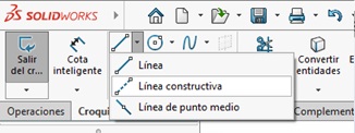
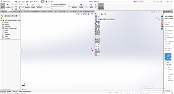
- Select construction line
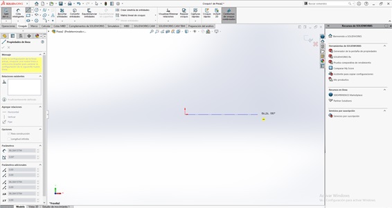
- select sketch
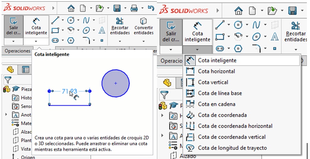
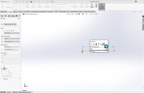
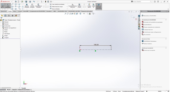
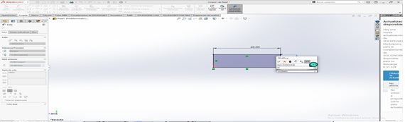
- Then click smart dimension
- Then select the side view
- then hide the plane
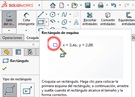
- Then select rectangle, from the point of origin
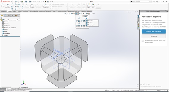
- Select Isometric View
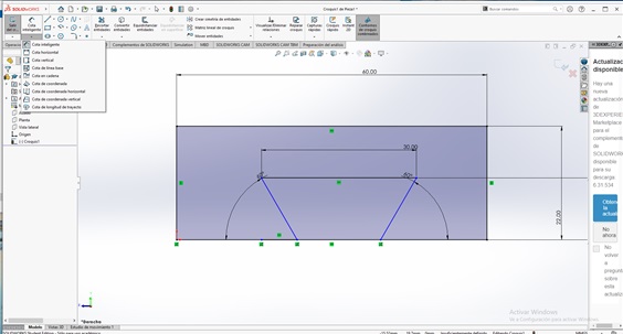
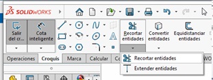
- Then clip entities
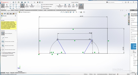
- Until fully defined
- Select the sides and place the same
- Then generate the new view
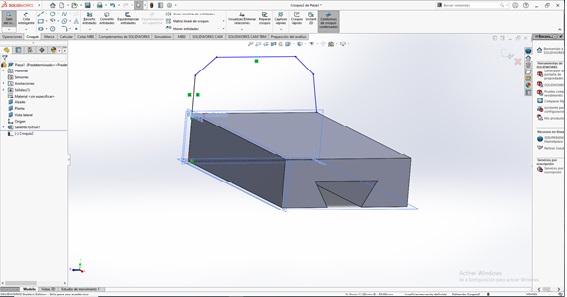
- Then place the angles of 45° and the distances of 16

- overall height 75
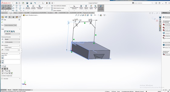
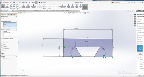
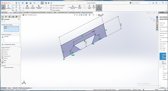
- Extrude forward 15mm
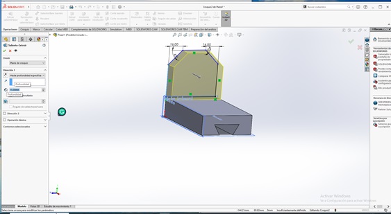
- Then select reference geometry, select plane

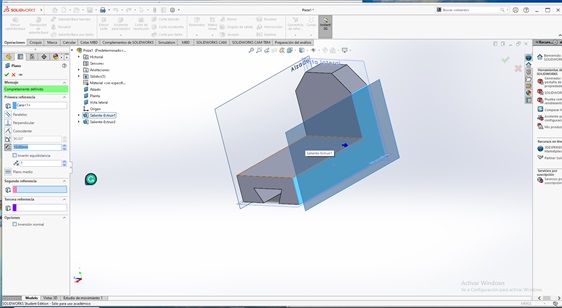
- In the middle plane build
- In the middle plane build
- Extrude 12mm from the midpoint
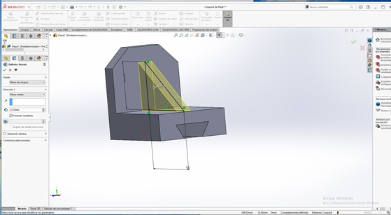
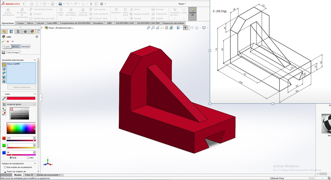
- Then change Appearance – Color
Modeling on 3D - Parameters
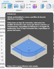
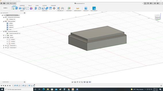
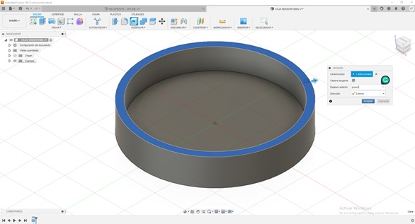
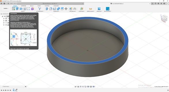
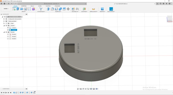
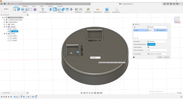
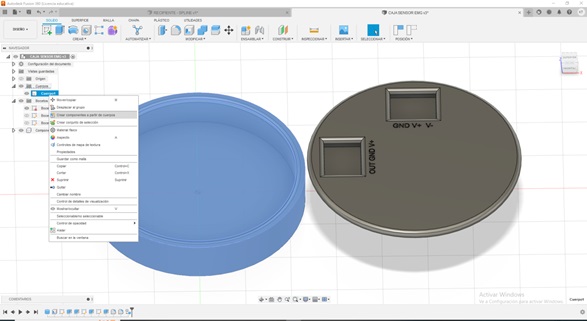
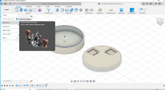
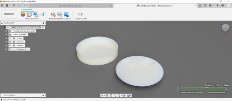
EMG SENSOR BOX
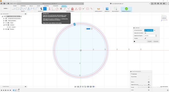
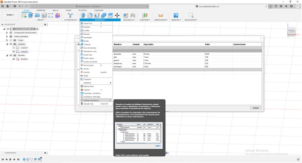
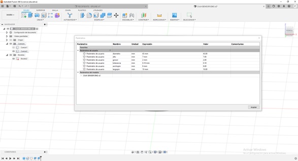
- Steps to follow to work in Fusion 360: Go to modify then select change parameters
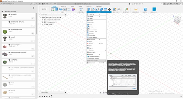
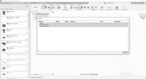
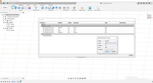
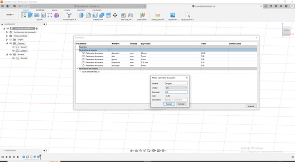
- Then click on the + to use parameters, then Add names
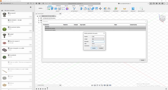
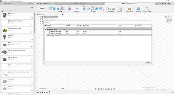
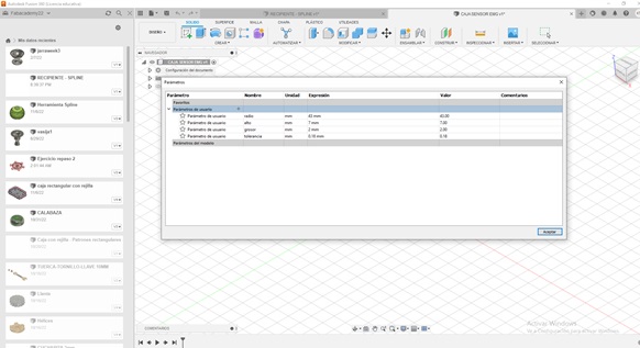
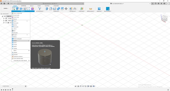
- Then accept, if you want you can also add more parameters… Then create a cylinder
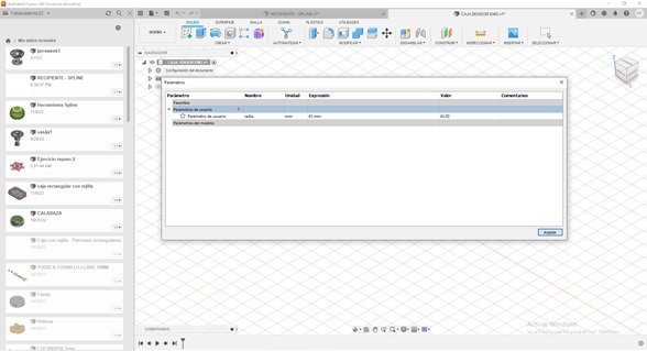
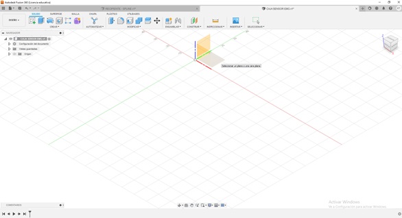
- Then click on the view and then accept
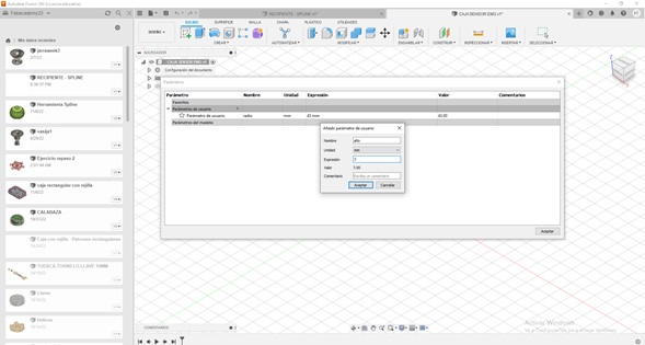
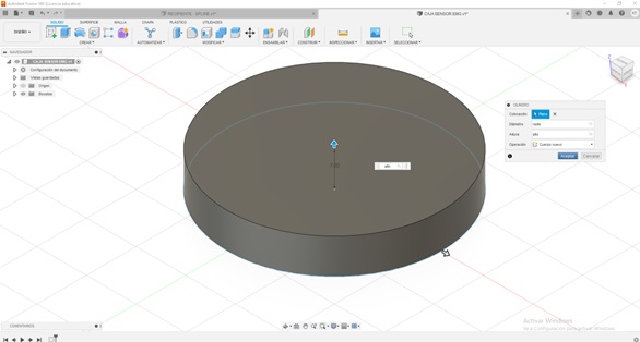
- Then click the center to input cylinder data, then put the parameter data
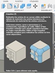
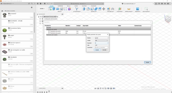
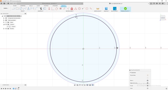
Then use the shell tool, place parameters
- Then create a new sketch on that face
- then project
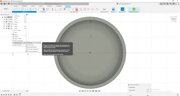
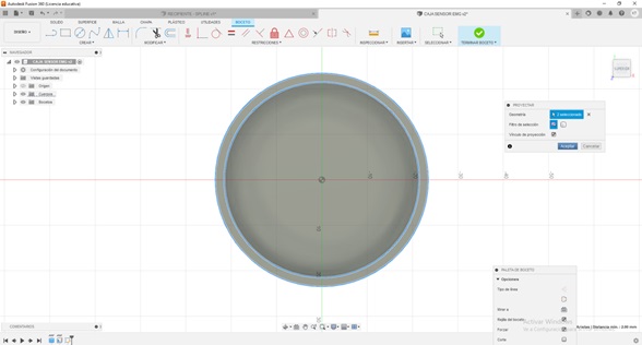
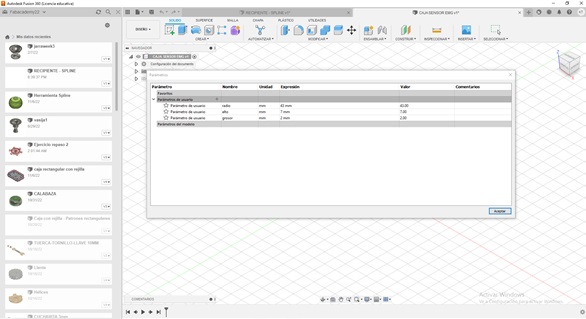
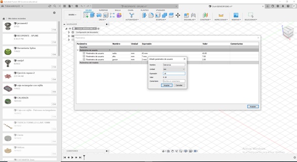
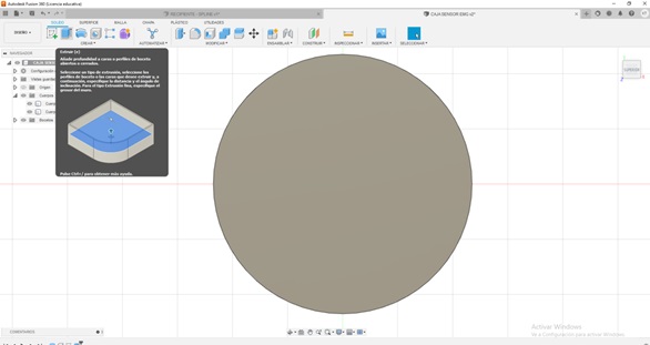
- Then hide the body, then apply the offset tool, then place the tolerance data of the parameters
- Then finish sketch or sketch
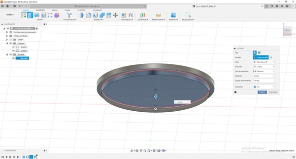
- Then extrude, placing data from the thickness parameter
- I can hide body 1, activate body 2 and activate sketch
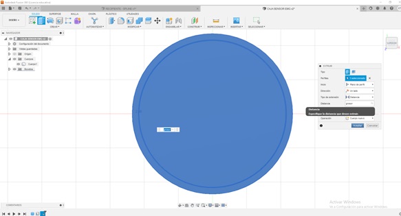
- Extrude sketch 2, in distance place the thickness parameter.
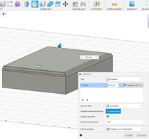
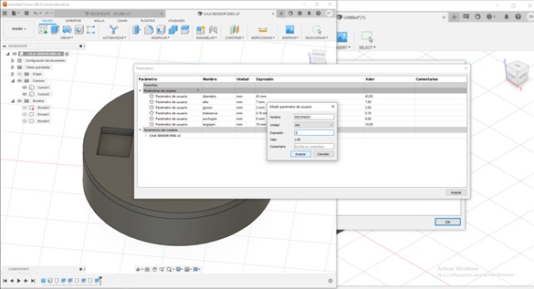
- You have to add parameters
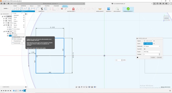
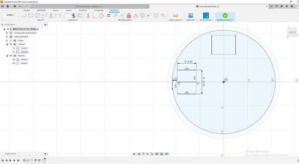
- Apply a circular pattern tool
- Add a parameter
- Then round is the fillet tool
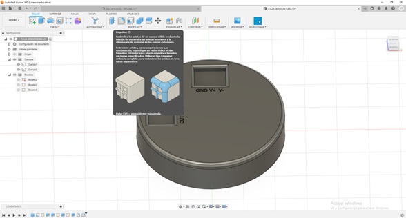
- Then the rounding /2 in the feed box
- Then right click with the mouse to displace one body from another, to generate the impression
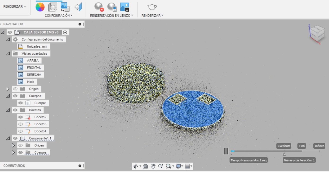
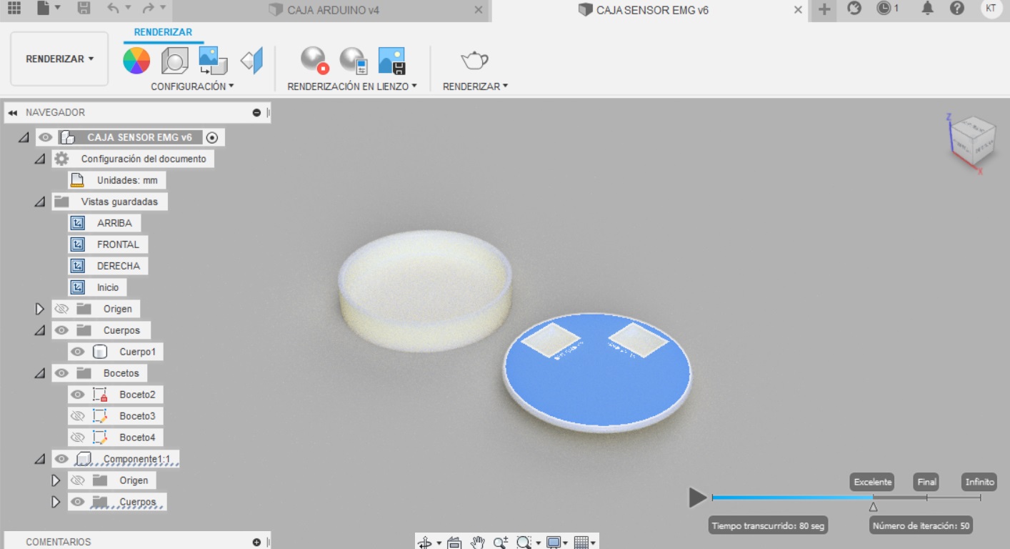
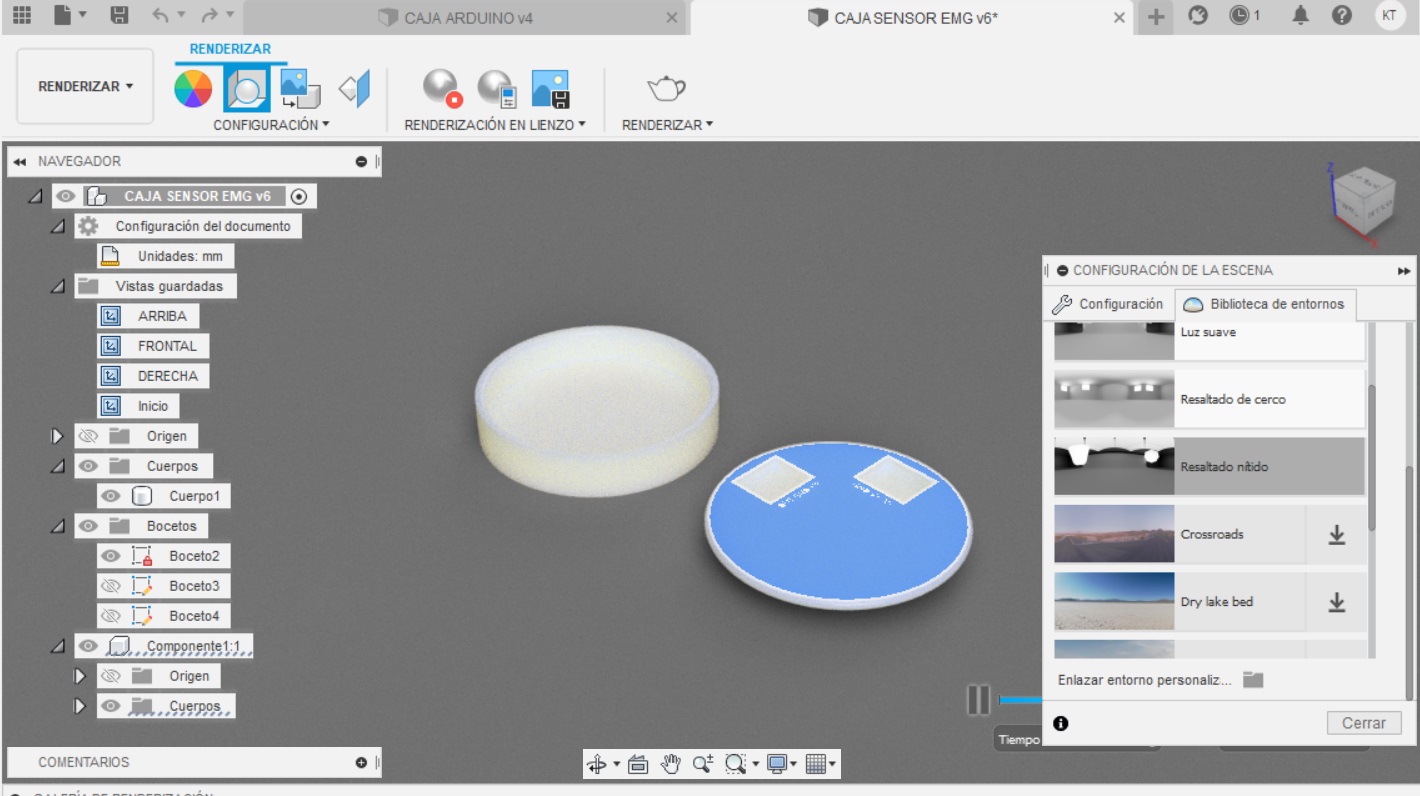
Modeling on 3D - Renderizado
- To render
Designing in 3D with Fusion 360 was interesting since I had not had the opportunity to work with this type of program, it seemed friendly to me because it is from the Autodesk family because I already knew something about AutoCAD but in 2D it brought me very close to this software with respect to the SolidWorks since it is very interesting and it seems more complete but I need to explore more about it, in my case I am working with Fusion 360 with an educational license and, in the case of SolidWorks my free license expires in 7 days so I have very little time left to explore for now.
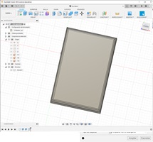
My box
-
[Fusión360]