Week 5: 3D Scanning and Printing
This week assignment is focused on 3D printing and scanning. The "3D printing" is the variety of processes in which material is deposited, joined or solidified under computer control to create a three-dimensional object adding a materials layer by layer. We are required to design and print 3D model that cannot be manufactured subtractively.
Instruction:
Design and 3D print an object (small, few cm3, limited by printer time) that could not be made subtractively.
3D scan an object (and optionally print it)
- To Do:
- Learn about 3D printers and how to operate.
- Learn about 'Subtractive and Additive' manufacturings.
- Design 3D model that cannot be manufactured using subtractive methods.
- Explore on 3D scanning and printing the scanned model.
- Group Assignment.
Background:
In the Manufacturing process of anything includes either 'Additive' or 'Subtractive' process. Additive manufacturing processes build objects by adding material layer by layer, while subtractive manufacturing removes material to create parts.
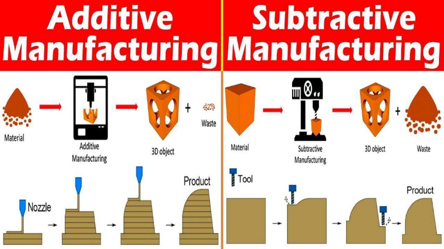
Image from google
3D printing is 'Additive' manufacturing as the process included are melting of filaments and stacking of thin melted filament on one another to form 3D objects.
- There are numbers of Advantages and Disadvantages for the 'Additive' manufacturing.
- Advantages:
- ☞ Create complex designs easily.
- ☞ Less wastage of raw materials.
- ☞ Faster route from design to production.
- Disadvantages:
- ☞ Not ideal for large quantity production as time consumption during manufacturing is high.
- ☞ It can be expensive.
- ☞ Has a limited range of materials compared to other processes.
3D Design:
This assignment is on designing 3D shape which cannot be manufactured using subtractive process. In simple, this means we need to create something where drill bit or endmill cannot reach (internal feature of object).
I planned to design planetary gear system where I will print whole system together. My design obviously goes in AutoDesk Fusion360.
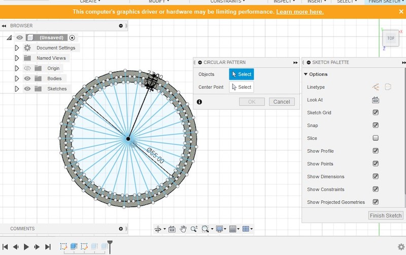
Had a hard time trying to design a gear in Fusion without any idea that there is gear generator plugin in Fusion.
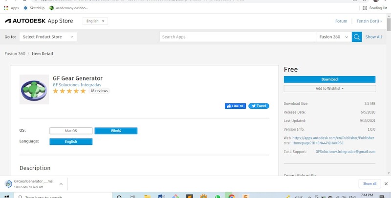
Later through the internet, I found there is actually the plug-in for gear generator. I downloaded the 'GF Gear Generator' and installed the plug-in. Installation steps are simple as just double clicking the downloaded file and plug-in gets installed and added.
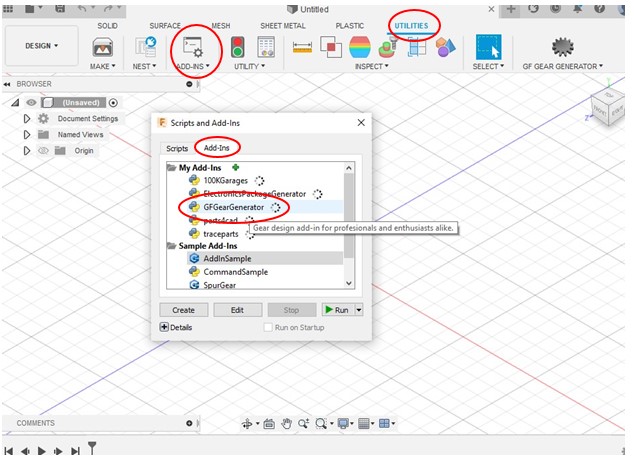
Once installed the package, you can find under 'Utilities' categories, 'Add-Ins' tab and 'Add-Ins'. Using the Add-in, you can easily create the gear with specific number of teeths, sizes and different styles. As I just needed the spur gear, I selected the spur and gave the specification as per my calculation.
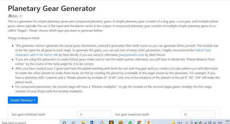
In order to create the planatery gear, I required the specific set of gears with ratio. I looked for the gear ratio generator online and found out 'Planetary Gear Generator'.
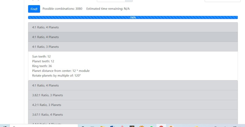
After giving the rough parameter, I got the numbers of option with different ratio and number of planet gears. I choosed the 4:1 ratio with 3 planets and I got the detail of numbers of teeths of ring, planets and sun gears.
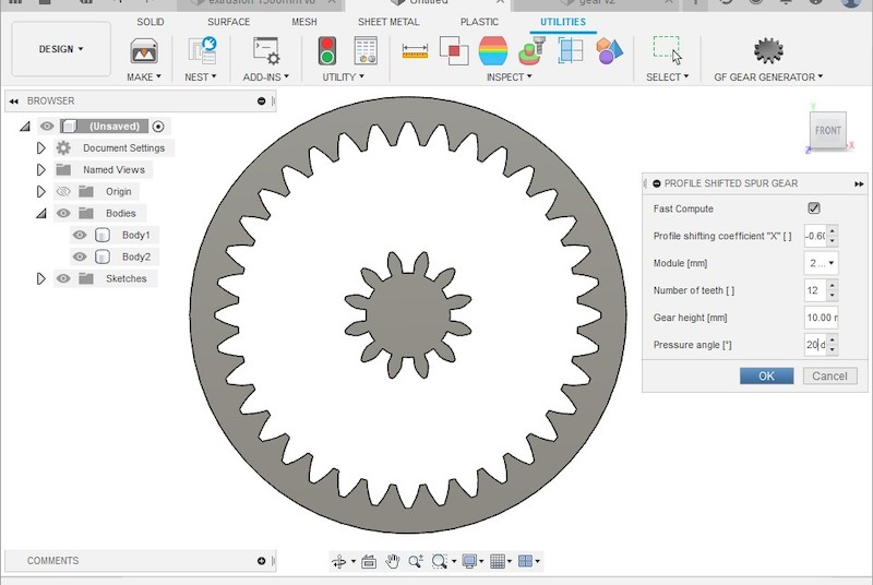
Referencing from the result I got from generator, I created the gears one by one. The ring gear needs to be 'Internal Spur Gear' while I used 'Profile Shifted Spur Gear' for my planet and sun gear. Ordinary 'Spur Gear' would have worked for Sun and Planet gears but due to 'Pressure Angle' for teeths gets much tight and would be hard for functioning. With the help of Profile shifted spur gear, I could easily manage the profile shifting of the teeths.
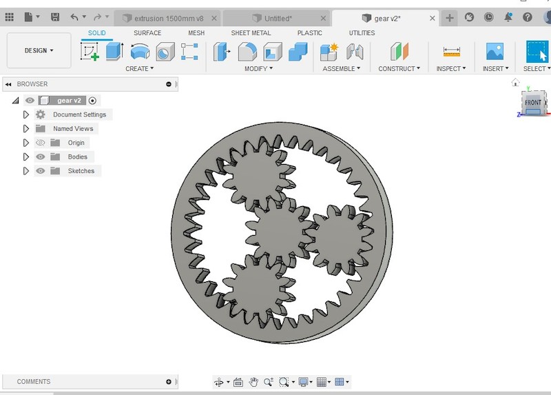
After creating the given numbers of Planet and Sun gears, I put the planet gears in place with the given angle of 120o. In order to shield the planet gears in place, I decided to sheild with external covering and I created covers on both sides.
In Planetary gear system, gears can be created with subtractive methods but all system together will be hard to be created subtractively. Simply even the covering on both side of the ring gear will be difficult to make with the teeth inside.

After completing the design, I exported the file in .stl format for printing.
Find .stl file Here
3D Printing:
Now, I need to print my model in 3D printer and see if it is working. In order to print, I have to first set the file for the printer with which filament we are using to print the model.
- 3D printing parameter as follow:
- Build Volume: 25×21×21 cm (9.84"×8.3"×8.3")
- Layer height: 0.05 - 0.35 mm
- Nozzle: 0.4mm default, wide range of other diameters/nozzles supported
- Filament diameter: 1.75 mm
- Supported materials: Wide range of thermoplastics, including PLA, PETG, ASA, ABS, PC (Polycarbonate), CPE, PVA/BVOH, PVB, HIPS, PP (Polypropylene), Flex, nGen, Nylon, Carbon filled, Woodfill and other filled materials
- Max travel speed: 200+ mm/s
- Max nozzle temperature: 300 °C / 572 °F
- Max heatbed temperature: 120 °C / 248 °F
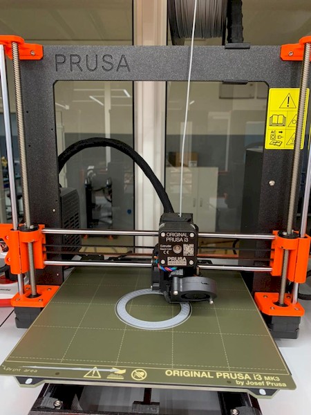
Here, I used Pursa with 1.75mm PLA filament to print my model. Created the Gcode file for the printer the set it print.
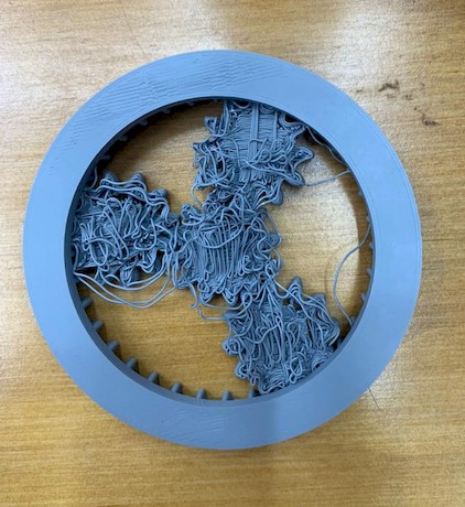
First, we tried to print without giving the support as it will be much easier for me and gear without having to remove the unwanted supports and much smoother surface if it worked. But sadly the result was above. As some parts are not on the plate, it couldn't be printed well and was wasted.
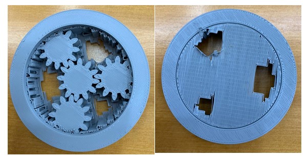
Second try with giving the supports and reult came out much better. All gear printed came out clear as expected. Only challenge left was to remove the supports. Removal of support from inside ring gear was bit challenging as it is inside.
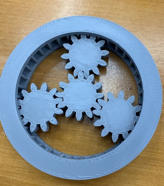
After removing the supports.
3D Scanning:
3D scanning is also the part of the assignment where we have to scan something and make it to 3D file.
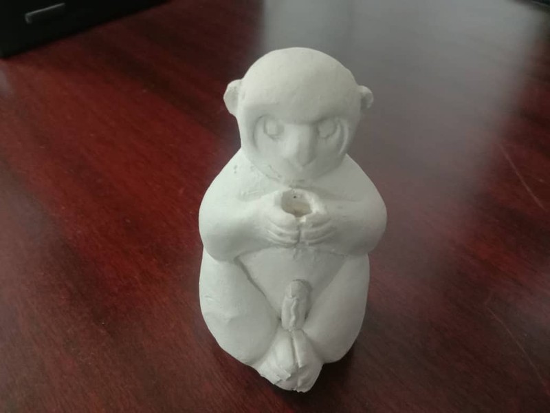
I tried to experience the scanning of this casted monkey. We used the Revopoint to scan the object.
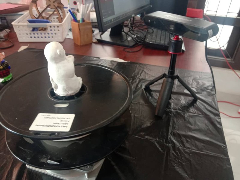
First thing is that, we required to setup item to be scanned. I made the base that can be rotated in order to ease the scanning of the item.
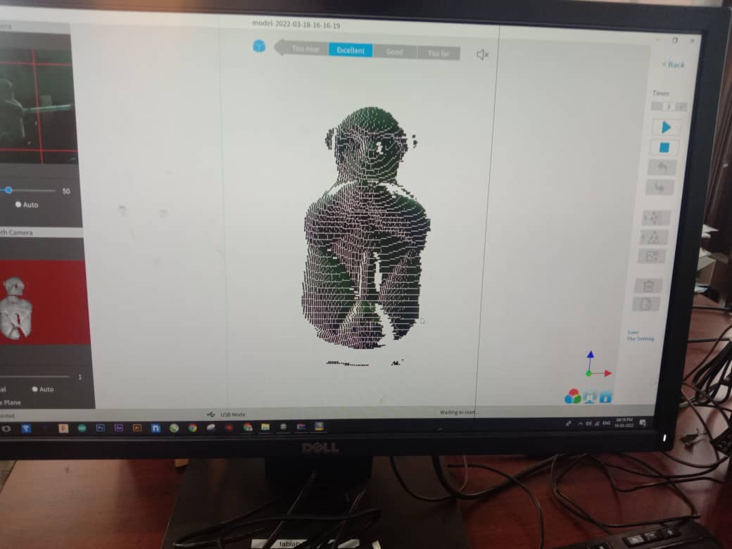
Item to be scanned should be align right in the center of the scanning camera. It requires some patient to get highlighted Excellent on the scale at the top. Once you get Excellent, you can proceed with scanning.
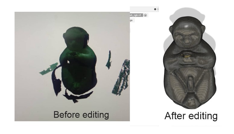
Fixing Scanned Data:
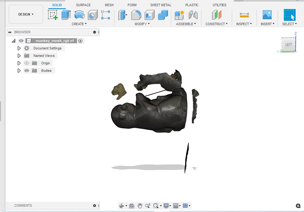
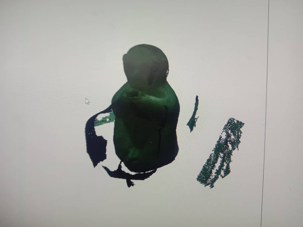
I used Fusion 360 to clean the scanned data. First I need to upload .stl file from scanned data to fusion. Than load into the work area and ready to fix the meshes.
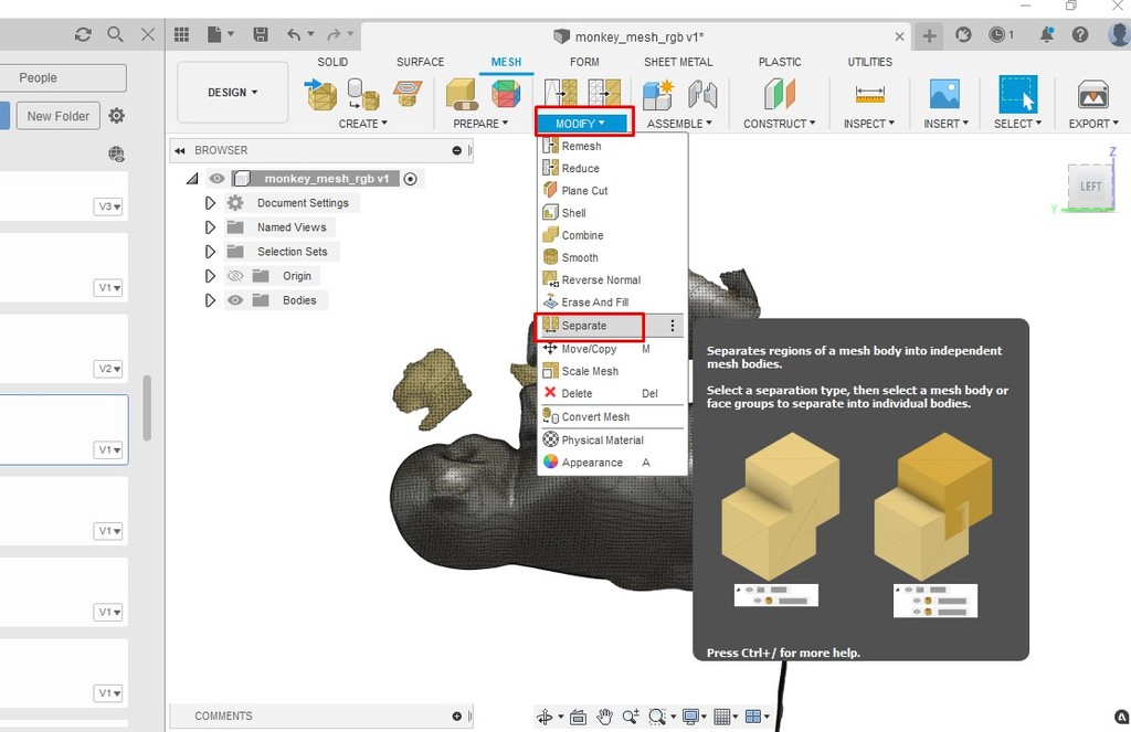
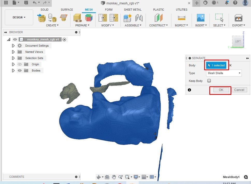
First we need to separate the different mesh in order to edit. Once separate, we can select different body indepedently. Now it's easy to delete unwanted body. I cleaned by deleting unwanted body. There wasn't much to edit other than deleting unwanted body.
Reference
- 3D printing: https://en.wikipedia.org/wiki/3D_printing
- Additive and Subtractive manufacturing: https://www.rapiddirect.com/blog/additive-vs-subtractive-manufacturing/
- Planetary gear generator: https://planetarygenerator.mateuszdrwal.com/