Week 6: Electronics Design
This week the main task is to explore and make our own PCB design with the PCB designing software. This is very important week for electronics where we are given the task to redraw 'Hello World' board.
From this week we can expect to learn PCB designing software, working principle of electronics and comprehensive PCB designing. This will help us in exploring more on electronics, especially about the fabrication of our own controller board for our final project.
Instruction:
Redraw an echo hello-world board, add (at least) a button and LED (with current-limiting resistor) check the design rules, make it, and test that it can communicate.
Extra Credit:
☞ Simulate its operation
- To Do:
- Learn about electronics and components.
- AutoDesk Eagle and fab library installation.
- Redrawing of 'Hello World' board with adding some additional components.
- Soldering the components.
- Program loading and checking.
- Group Assignment.
Electronic Components:
There are many electronic components such as transistors, resistor, controllers, capacitor, inductors and all. Types of components are even clasify as Surface Mount(SMD) components and Through Hole components.
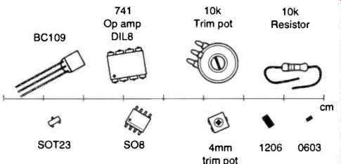
Image from google
Above one is the 'Through Hole' while lower ones are 'SMD' components. SMD components are relatively smaller in size compare with same component of through hole. SMD gives advantages of space to fabricator compare to through hole components because of it's smaller size reducing the board size by more than half.
In Fab Academy, we will mostly be using SMD components.
Resistors:
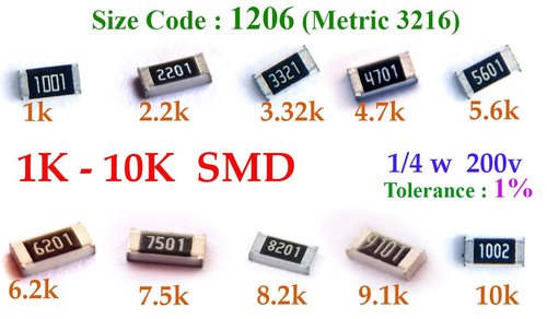
Image from google
A resistor is a two-terminal electrical component that implements electrical resistance as a circuit element. In electronic circuits, resistors are used to reduce current flow, to divide voltages, and terminate transmission lines. Resistors are one of mostly used components in electronics circuit.
Transistors:
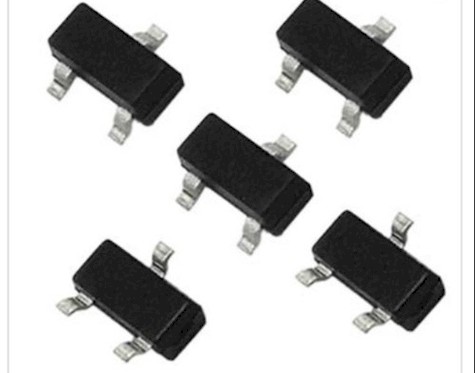
Image from google
A transistor is a semiconductor device used to amplify or switch electrical signals and power. The transistor is one of the basic building blocks of modern electronics. It is composed of semiconductor material, usually with at least three terminals for connection to an electronic circuit. From WiKi.
Capacitors:
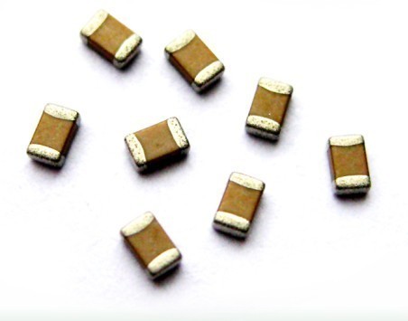
Image from google
A capacitor is a device that stores electrical energy in an electric field. It is a passive electronic component with two terminals. The effect of a capacitor is known as capacitance. While some capacitance exists between any two electrical conductors in proximity in a circuit, a capacitor is a component designed to add capacitance to a circuit. The capacitor was originally known as a condenser or condensator. From WiKi.
AutoDesk Eagle:

It is the PCB designing software owned by AutoDesk Fusion. I choosed Eagle out of other designing software because I already have access to AutoDesk license and it is also reliable and user friendly. It's environment of circuit designing are volatile and effective.
In order to design Fab circuit, we need to add fab library of eagle in the software. There will be components required for circuit designing, but installation of library will give easy access to every components required for Fab circuit designing.
Adding Library:
Searching for components we required through whole lists of eagle's components will really be hectic during circuit designing. Wide range of components even classified under manufacturers are present in the eagle library.
So, Fab lbr gives comprehensive, well selected and only required components for FabAcademy circuit designing. It will be eassy for us to find our required components from fab lbr file.
Find Fab lbr Here.
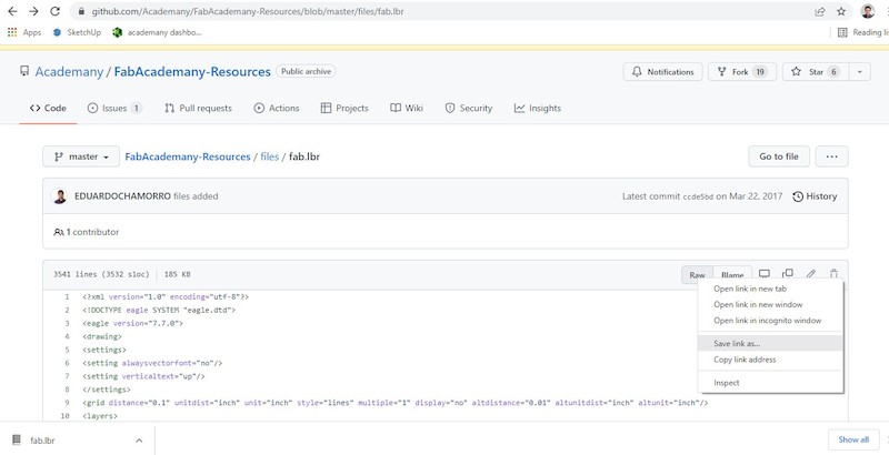
Here comes the critical thing we need to concerntrate to add fab lbr to our eagle software. Most do not give detail on how to download and add the file. In the given link above, we will just see the source code for the library. So, in order to download as library file:
Right click on Raw >> Save link as
This will download as library file in the given directory.
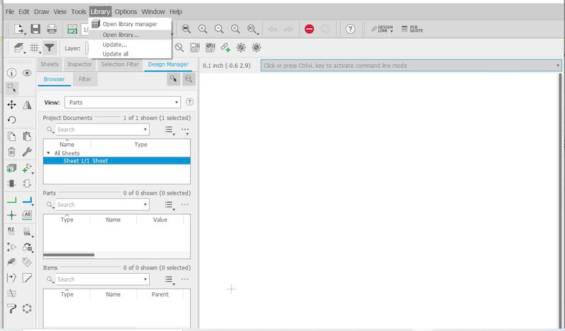
Now in order to 'add' downloaded file to library:
Open the eagle software -> From the File >> New Open new project Schematic -> On the Schematic task bar -> Click on Library -> Open Library Manager -> Available -> Find Fab -> Click Use.
Now you can find the library added
Redrawing HelloWorld Board:
Main assignment is to redraw the 'HelloWorld Board' adding atleast one resistor and a led. As I already setup my Eagle software with library of Fab Academy, now I can go with adding components required for the board and start designing the circuit.
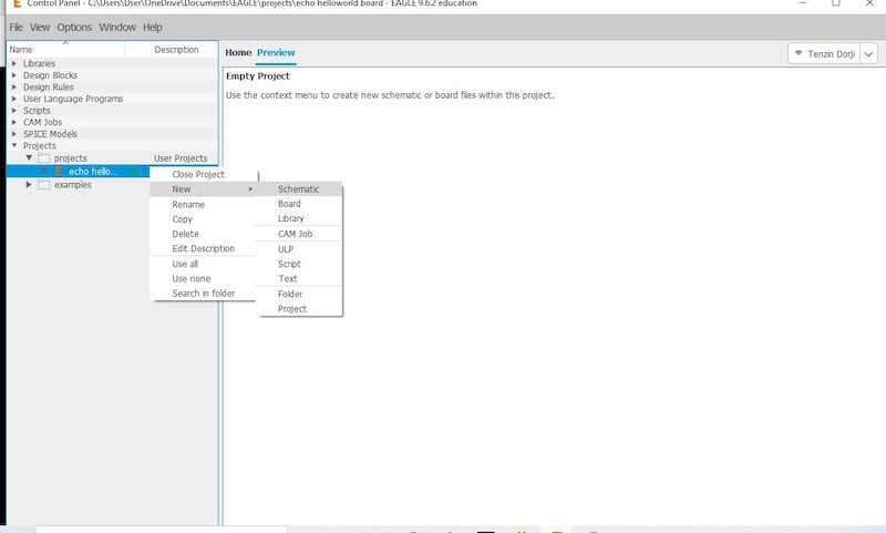
From the 'New' tab, create the new project and name it accordingly. Under the 'Project' drop down as shown above, go to 'New' and open 'Schematic' in order to create the circuit. This will let you to the new schematic drawing page.
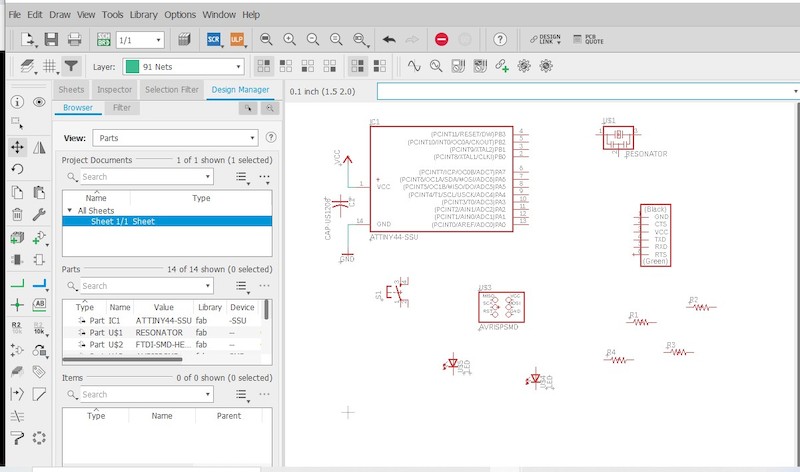
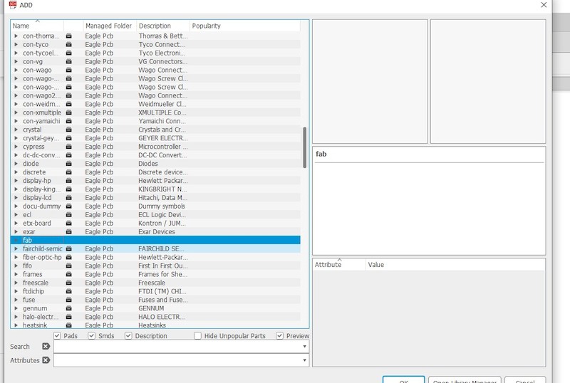
Once in the Schematic, using the 'add' comment add the components you require for developing the circuit. When you give add comment, it will lead you to many component libraries of eagle. You can choose 'Fab lbr' which you will find as 'Fab' once added in the library. From this library, you can much easily find the components you required for FabAcademy.
- Components required for the redrawing of 'HelloWorld' board are;
- ATtiny 44,
- Two LED 1206,
- Three Resistors R1206 (You can add 0ohm if needed as jumper),
- One Capacitor C1206,
- One FTDI-SMD-HEADER,
- One Omcron Switch, and
- One AVRISP Also add source of VCC and GND.
Now we have to make the connection as per the given. In the above circuit, I have also added the source LED and another LED which I can use to program later. I also added the programmable button in the circuit.
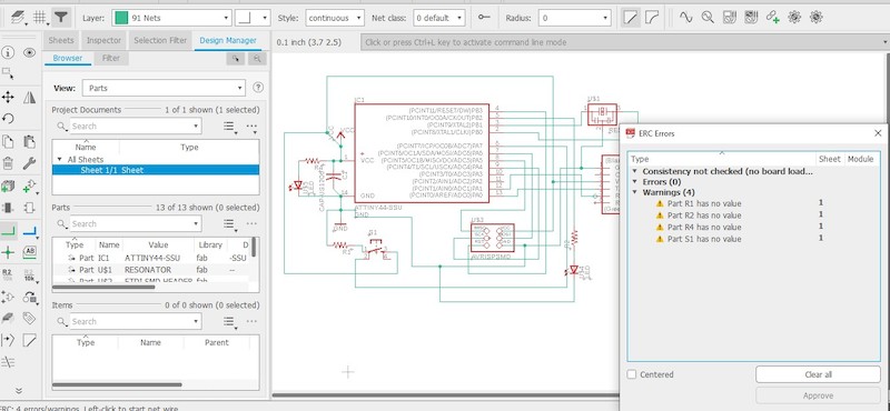
After the connection, we have to run ERC to check our circuit. Usually the cross connection and miss connection are found out from running ERC. There will be also the warning for the value of the components but we can ignore that.
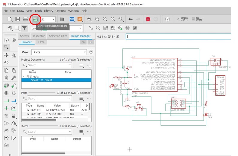
Once done with Netting, you can navigate to board by selecting 'Generate/Switch to Board' icon as shown above.
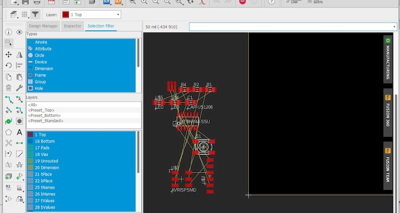
Once in the Board environment, we need to arrange and wire the circuit. Wiring requires very careful plan in order not to cross the wires on each other. In unavoidable circumstances you cacn use 0ohm to bridge the wire and crossing over other, but it is a good practice to try not using one.
In order to wire the board successfully, it is imortant to understand the design rule.
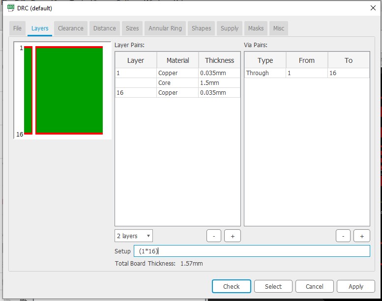
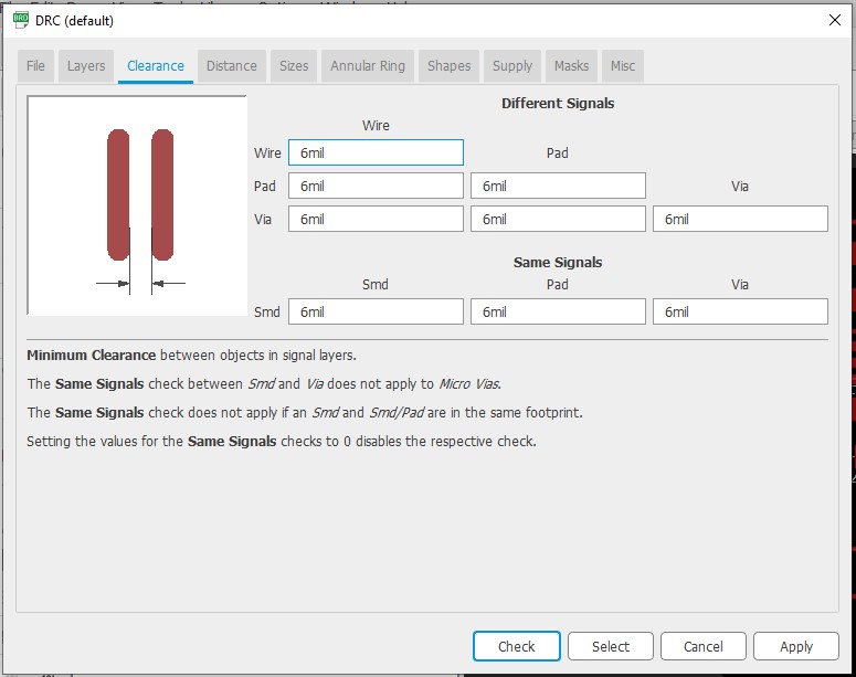
This is the basic design rule which we have to consider during the design. This usually checks the minimum size of the wire, minimum distance between the wires and components, though we have to consider the real width of the wire according to the amount of current that will pass through it.
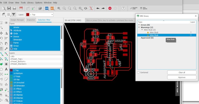
So, I tried my best and the rough completed wiring as above. I need not have to use extra 0Ohm wire to bridge. After thecompletion, I ran DRC to check the validity of my wiring. There wasn't major problem despite of some wire stubs left while deleting and adding the wires again.
You can easily delete them as it is visible when tab on the error shown.
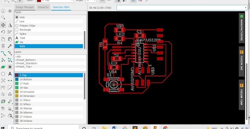
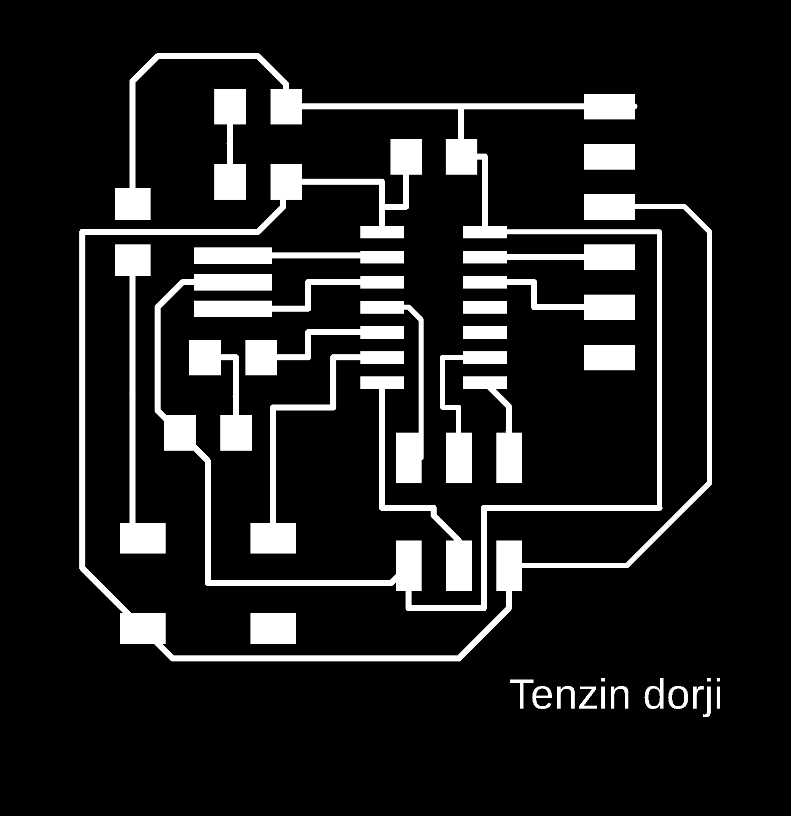
Completed wiring board after removing the warnings. Once ther is no error left, it will not show anything when you check in the DRC.
Now we are left with is to add the outline of the board that we will require to cut after the printing. For adding the outline, select the 'Dimension' from the layer and you can draw any shape as the board outline. It's important to keep safe distance between circuit wires and outline.
Error:
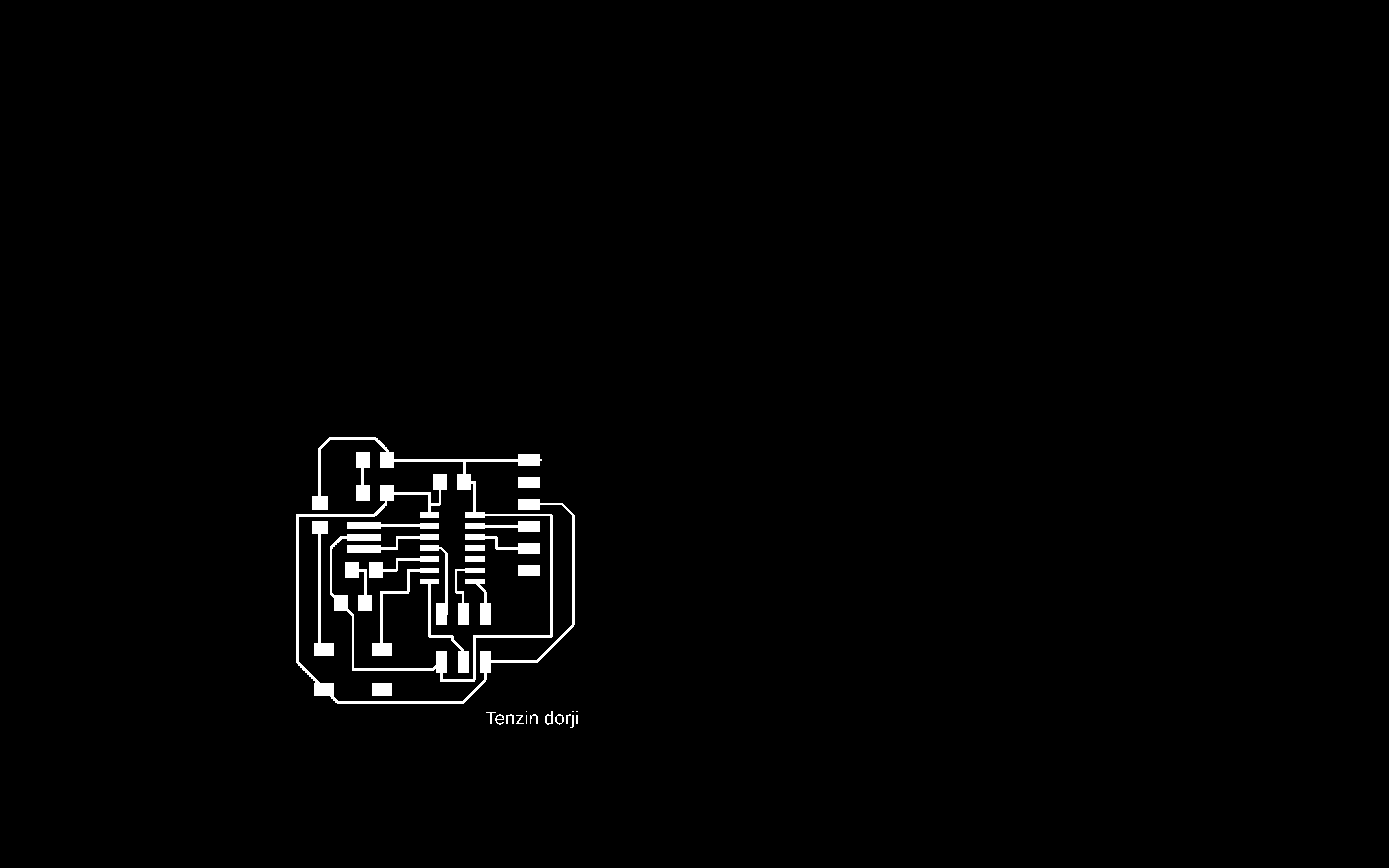
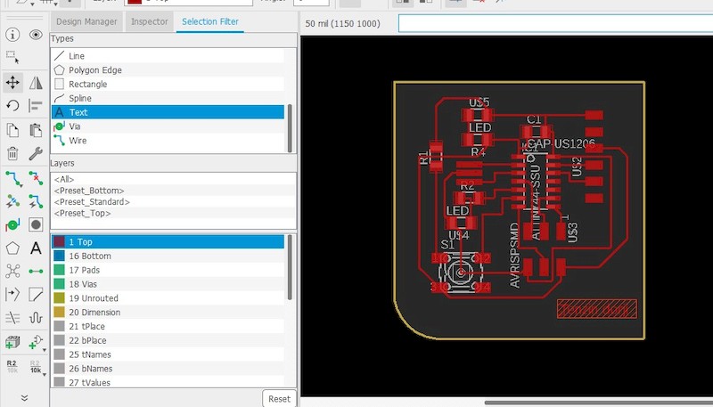
Once everything are completed, I tried to export in image form selecting monochrome. But instead of just a circuit, the exported image shows whole page. I had a tought time finding it out.
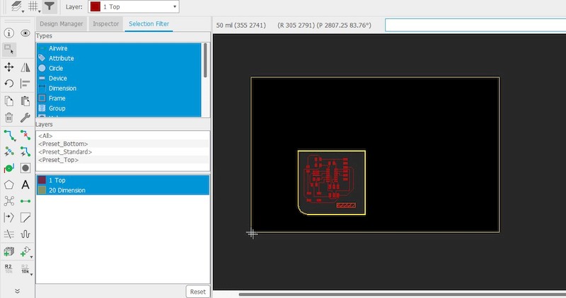
Later consulting with the local istructor and going through google found out that I haven't deleted the pre-existing outline after constructing my own outline. Selecting of whole 'Types' under 'filter' is required to edit particular outline. After deleting the outline, everything cames fine.
Find my files here:

Milling Board and Programming:
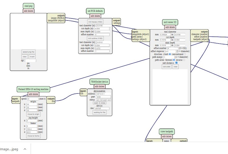
Milling process involve of making print file from 'MIT MODS' and saving. On the browser search mit mods, opening that will navigate to mod space. 'Right Click' on the space and select 'Program File', look for SRM20 and open it.
Create the file for trace using 'mill Traces' option under Set PCB Default and 'Mill Outline' option for outline cutting.
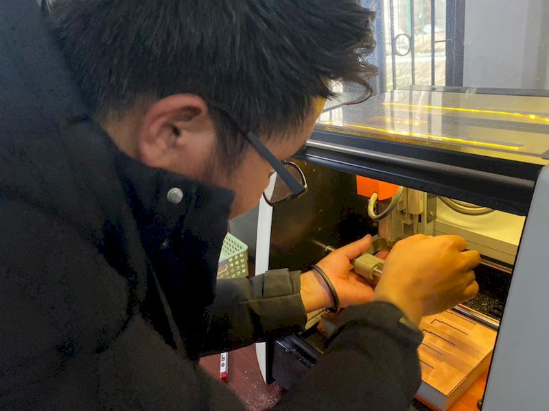
Set the milling Machine with the required end mill for tracing and mill the circuit out. After milling the circuit, change the end mill required for cutting. Need to set Z zero but keep the X and Y coordinate untouched. Cut out the outline of the board.
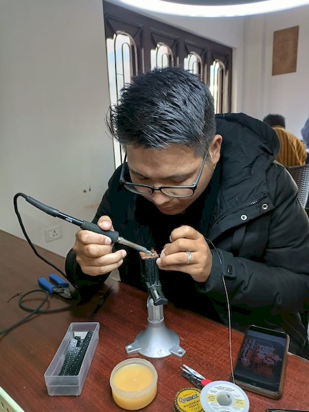
After milling, it is important process where we need to solder and place all the components togather. Soldering of SMD components are really challenging and takes much time. I made sure not to make wrong soldering. It is very important to check the anode and cathode of the components like LED and capacitor. Also need to make sure of the right orientation of the terminals of ATtinny44.
A good practice during the soldering is checking of connectivity after every soldering of single components. This will reduce making of short connectivity or loose connection. Usually trouble shooting after the completion of soldering will be hectic work as we cannot point out the fault easily.
Programming:
I used Arduino as ISP to program my board. In order to program the ATtiny board, you need a library of attiny in the arduino software. Unlike other libraries of Arduino, library for ATtiny44 cannot be found in the board manager directly.
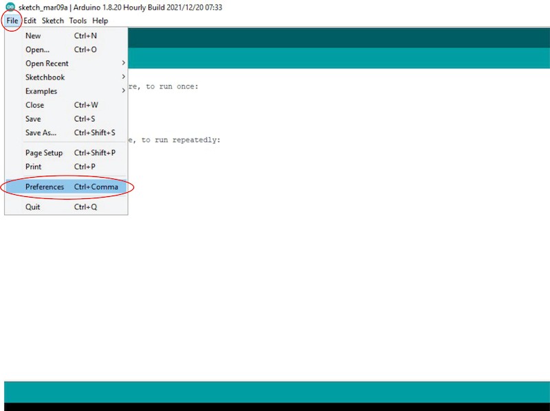
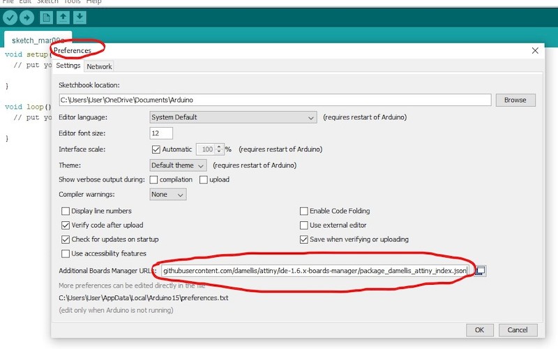
So, as shown in above images, go to 'File' and 'Preferences'. Under the Preferences group, you can find Additional Boards Manager Url: where you need to add this url https://raw.githubusercontent.com/damellis/attiny/ide-1.6.x-boards-manager/package_damellis_attiny_index.json.
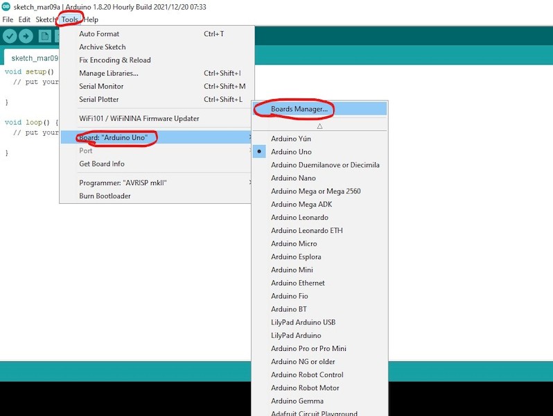
Now, 'Boards' under Tools and 'Board Manager', you can search for ATtiny library.
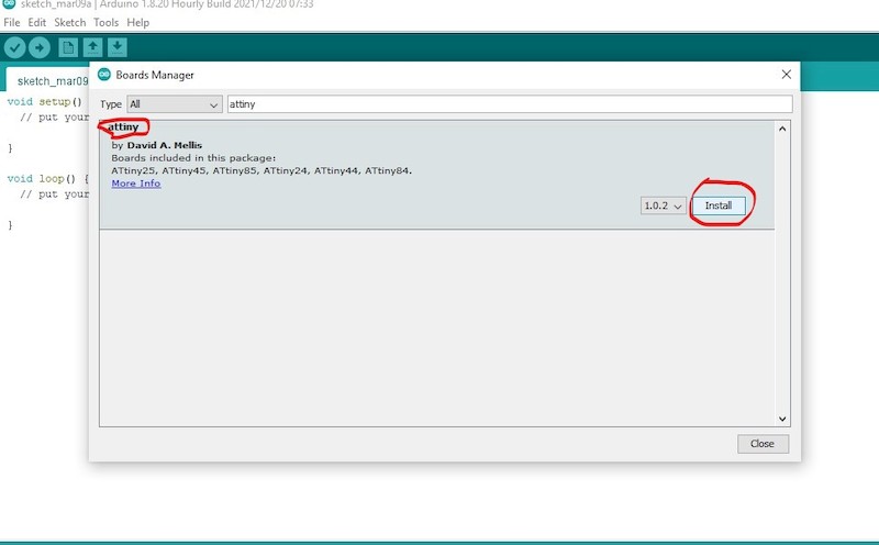
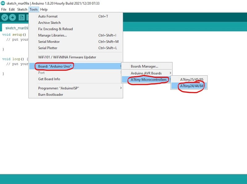
After the installation of library, now you can see the ATtiny board available under the board option. You can choose your required ATtiny board.
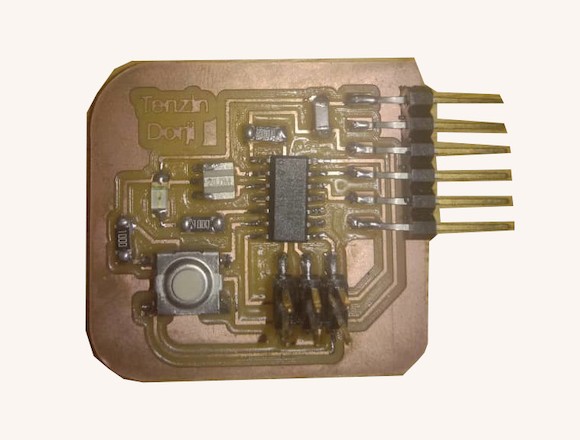
Now using ATtiny44 as a board and ArduinoISP as a programmer, I loaded the program to my HelloWorld board.
Programmed with Arduino
In order to make sure that the led is not controlled from Arduino, I tried with just supplying the power, disconnecting other wires.
Reference
- SMD and Through hole components: https://www.industrial-electronics.com/bab-411_1.html
- Additive and Subtractive manufacturing: https://www.rapiddirect.com/blog/additive-vs-subtractive-manufacturing/