Week 3: Computer Controlled Cutting
This week is more about practical. We are required to design and cut using laser machine. We also need to test the power and speed of laser machine presented in the lab. But we are also not to leave the vinyl cutting aside. Practical sounds more interesting after lots of theory and heavy work with the documentation.
Instruction:
Cut something on the vinylcutter design, lasercut, and document a parametric construction kit, accounting for the lasercutter kerf, which can be assembled in multiple ways, and for extra credit include elements that aren't flat.
- To Do:
- Design something to cut on vinyl
- Cut the design in the vinyl and experience the it
- Design parametric construction for laser machine.
- Document on parametric design you did.
- Group assignment on learning about the laser machines presented in the lab:
👉 Type of laser machine,
👉 Lasercutter's focus, power, speed, rate, kerf and joint clearance.
Vinyl Cutting
In this week assignment, one of thing we required to do is vinyl cutting. Vinyl cutter is one of the most under appreciated machine present in the fablab as mentioned by Neil. In the market, vinyl cutters are extensively used to fibricate signs and signboards. Even number plates for the cars are fibricated using vinyl in our country.
Vinyl Cutter detail:
The vinyl cutter at our lab is the Roland CAMM-1 GS-24.
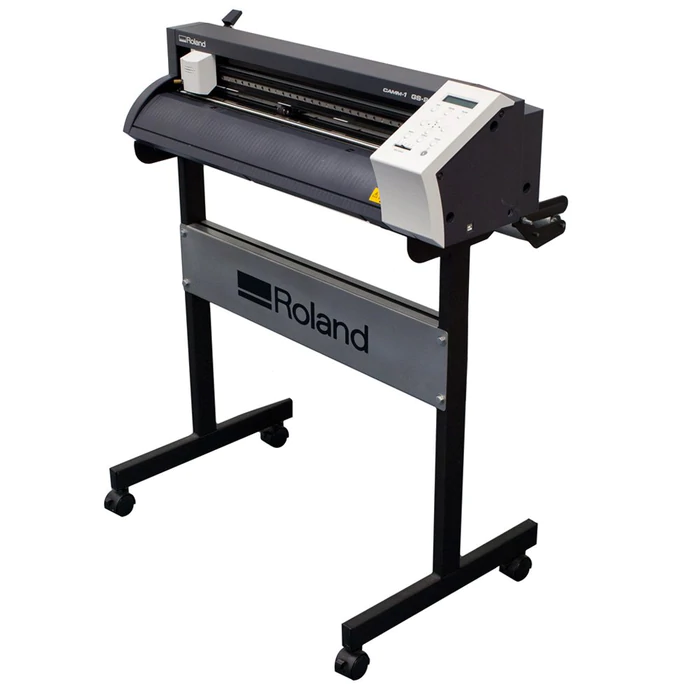
Image from google https://www.totalinksolutions.com/products/roland-gs-24
The Vinyl cutter comes with 3 types of cutting blades, each with different angle as shown below.
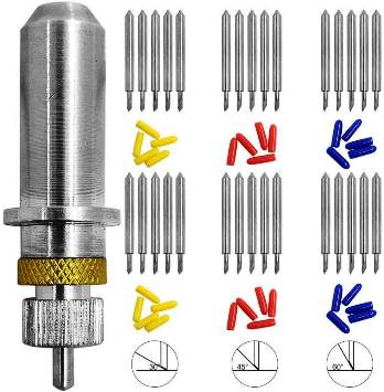
There are three types of cutting blades based on angle on inclination of 30, 45 and 60 degrees. We need to use High Power, Lower Speed and larger angle of inclination for Harder Materials like Copper and Low Power, Higher speed and lower angle of inclination for softer materials (Vinyl).
Cutting parameters:
| Max. cutting area | Width: 584 mm (22.9 in.) Length: 25 m (984 in.) |
| Max. cutting speed | 500 mm/s (all directions) |
| Cutting speed | 10 - 500 mm/sec (4 in to 19.69 in/s) (all directions) |
| Blade force | 30 - 350 gf |
Vinyl Cutting:
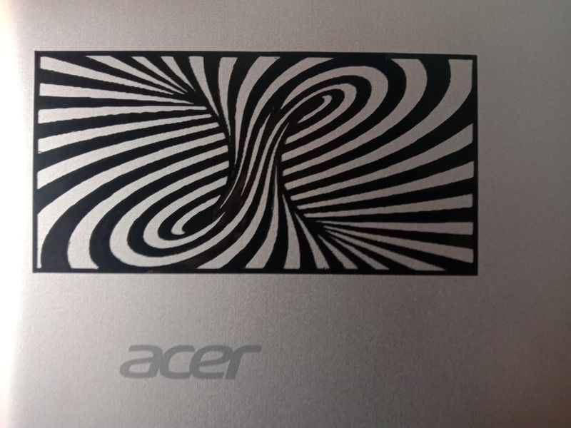
In fablab, vinyl cutter is mostly used for screen printing and making of stickers. So, for this assignment, I also tried to make a 3D illusion stricker.
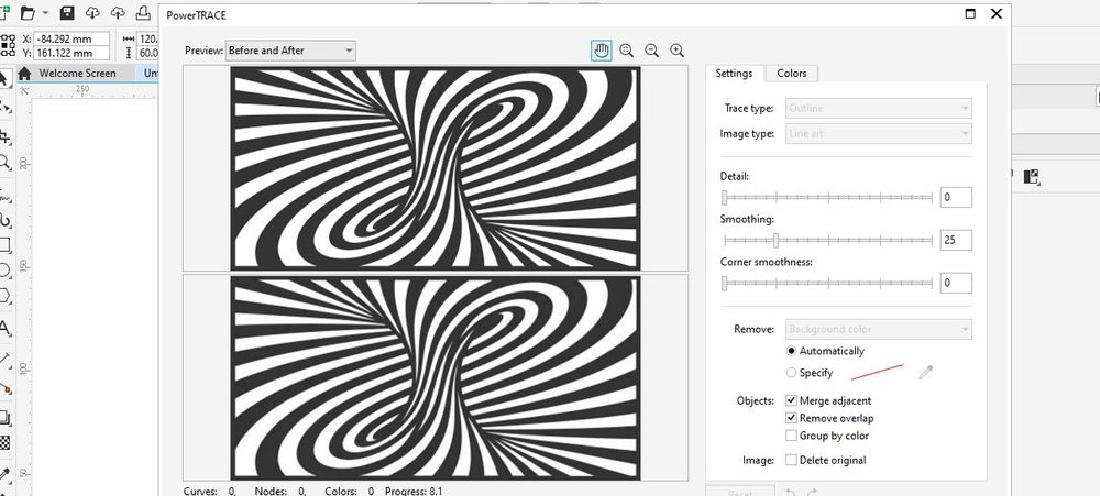
I downloaded the 3D illusion image from the internet and tried to trace bitmap. I traced the outline of image using outline trace option
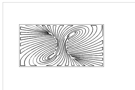
After tracing the outline, I export the image in svg format in order to open in the easycut for vinyl.
Vinyl Setting:
☞ Lossen the roller wheel using lever attached.
☞ Set the on the white dashed lines on the vinyl.
☞ Put the vinyl sheet beneath the wheels and lock the wheel using lever.
☞ Now press the Origin button on the vinyl machine and than press Enter button.
From EasyCut on desktop, on the cutter option, select the cut button and work will be set on.
- For this work as we have used the plastic sticker vinyl sheet, following settings were used:
- Cutting Force 30 gF
- Speed 20cm/sec
- Blade Cutter with an cutting angle of 45degree.

Earlier I tried with the blue color sheet. But I later found out that there is already some pattern print on it, so, I had to cancel the print. I also found out that the printing wasn't clean and talked with instructor and found out there was clotting on the cutter.
Find Original File Here
Laser Cutting
Laser Cutter:
In Fablab Mandala, we have epilog laser cutter with the cutting parameter of 609.6mm by 304.8mm with the power of 40 watt.
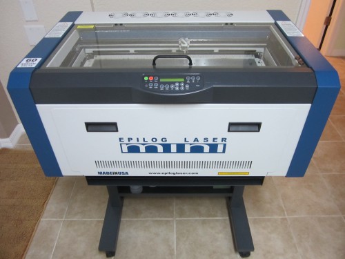
Image from https://www.laserresale.com/?fa=app.view&it=6319
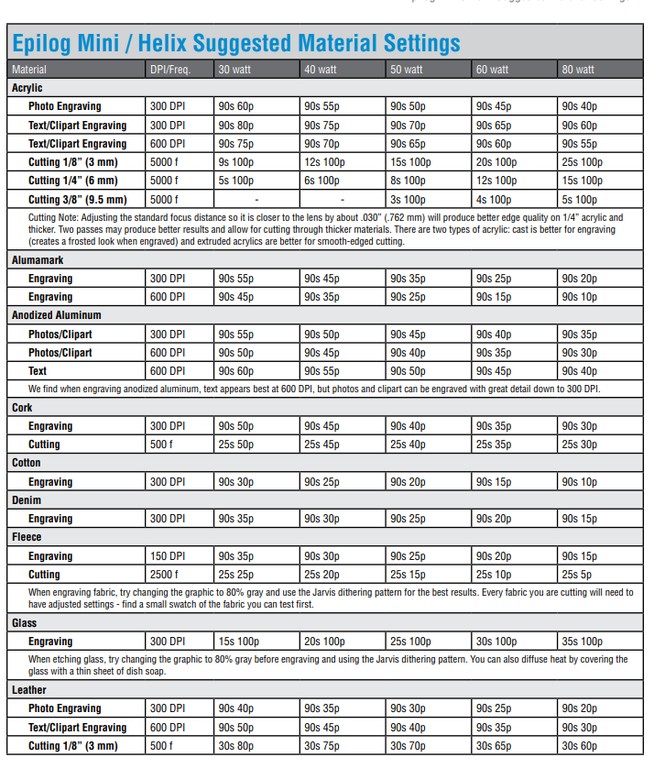
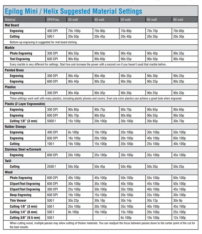
Printing parameters:
For different materials printing and cutting requires different power and speed. Attached below shows power setting for different materials:
Parametric Design:
It is the design that gives the freedom to change its features using different variables. Parametric designs are freely adaptable with the change in the size or width of the materials. Once we complete the parametric design, we can change it's size of depth or thickness easily using variables according to our requirement. Flexibility gives this technique the power to be adapted to the needs of places or people.
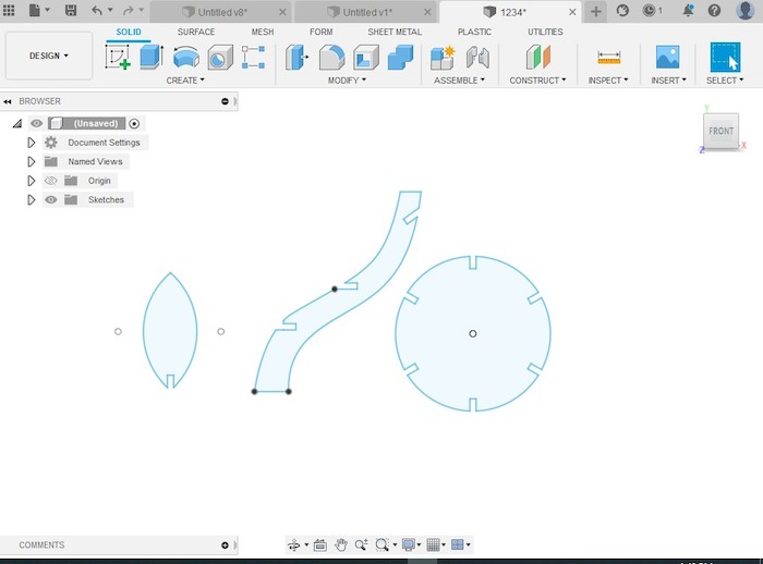
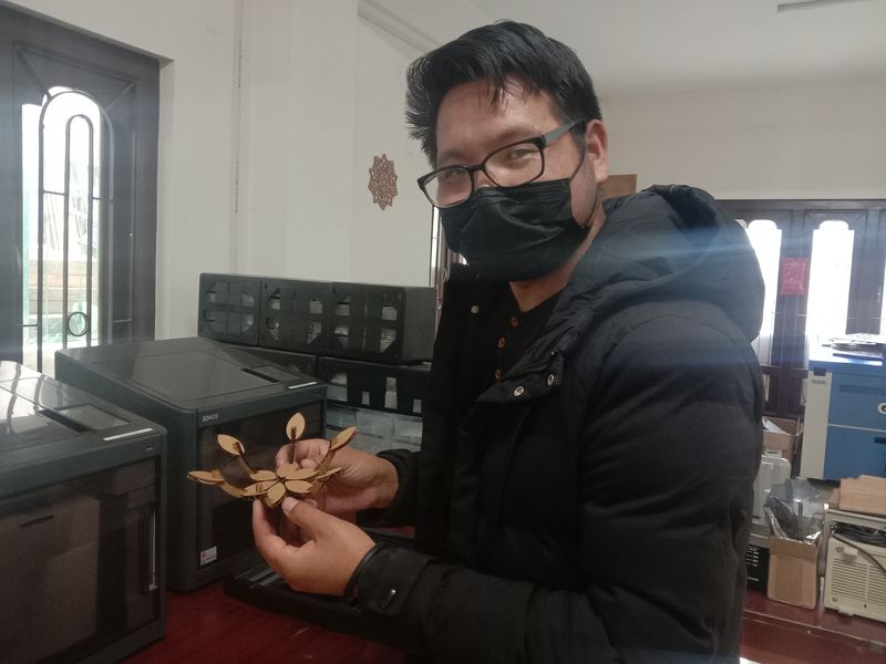
So, we are required to create a parametric design and cut in laser machine. I tried to design a plant shape on fusion which I saw in pretty good shape on internet.
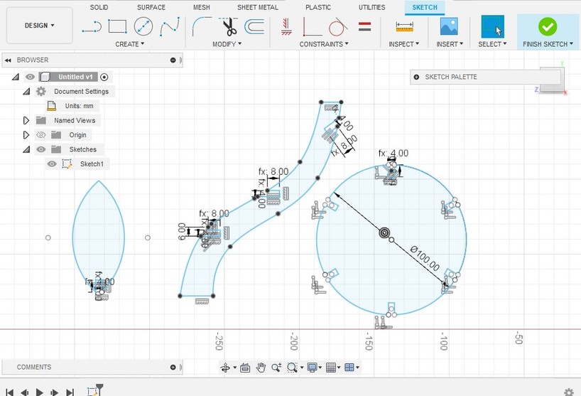
I tried to design these three items to make entire object.
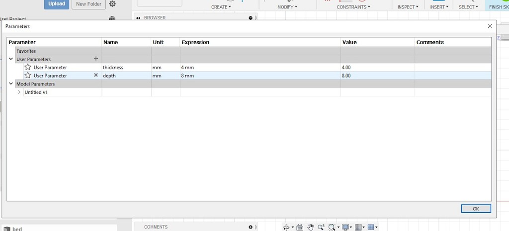
I set the pre-parameters which I later used instead of number on the dimension. I used depth parameter to set how deep the the hinges are required. I can change all the depth of design using this parameter.
And I used thickness parameter to set the thickness of the materials. It is really handy when we are not sure of how thick our materials would be. In designs, the width of the fits are usually the thickness of the material. So, using the thickness parameter set earlier, I can access easily to change it as per the thickness of the materials I will be using to fabricate it.
- Set parameter in design are:
- Thickness of materials as 4mm
- Depth of interlock as 8mm
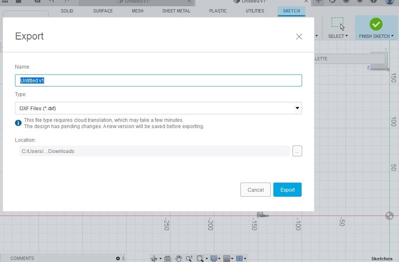
Since laser machine and CNC machines usually requires the dxf file format, I tried to export my design in dxf format. The file exported really comes out error and I couldn't get the required file I need.
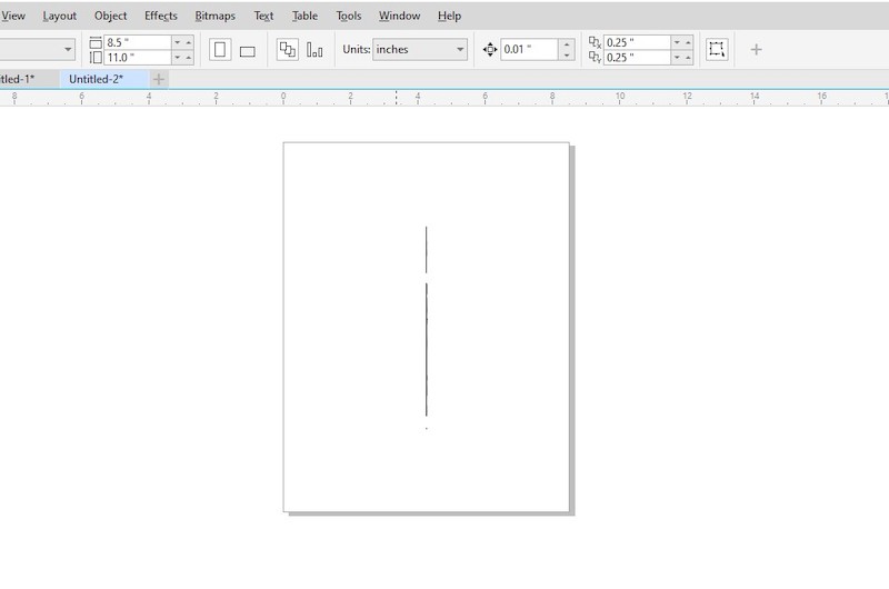
When I check the file that was exported in the coreldraw, I just got the lines, not the design. I thought it might be because of faces I haven't set in the design cube. I tried to change the face to front and than top, but still I couldn't get it right.
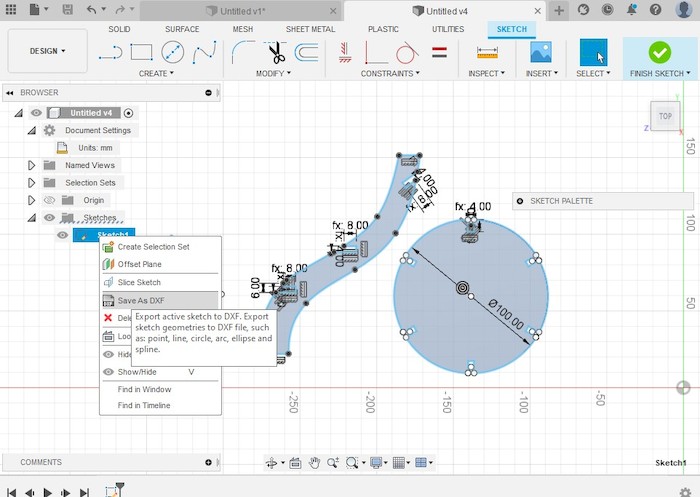
Later I found Save as DXF from the sketch in the design page. I could successfully save the design and tried checking in the coreldraw.
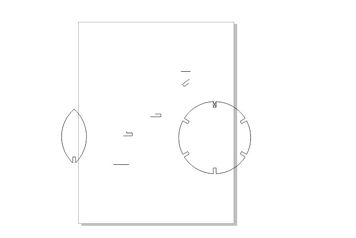
Result was satisfactory but I still lost some part of drawing. I tried again many times consulting with the local instructors.
This video helped me a lot which is shared by my instructor. I followed all the steps but the result came out same while trying to open in CorelDraw.
Later in the video there is given that they are checking the file in fusion360. So I tried loading in fusion and all the contours are in tact.
Find Original File Here
Design Cutting:
Later I resolve into editing from exported file and started my cutting.
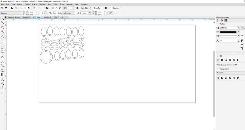
It is always wise to be mindful of our space and arrangement of our design to cut. So, I tried to use minimum space as possible as it will save the amount of materials I am using.
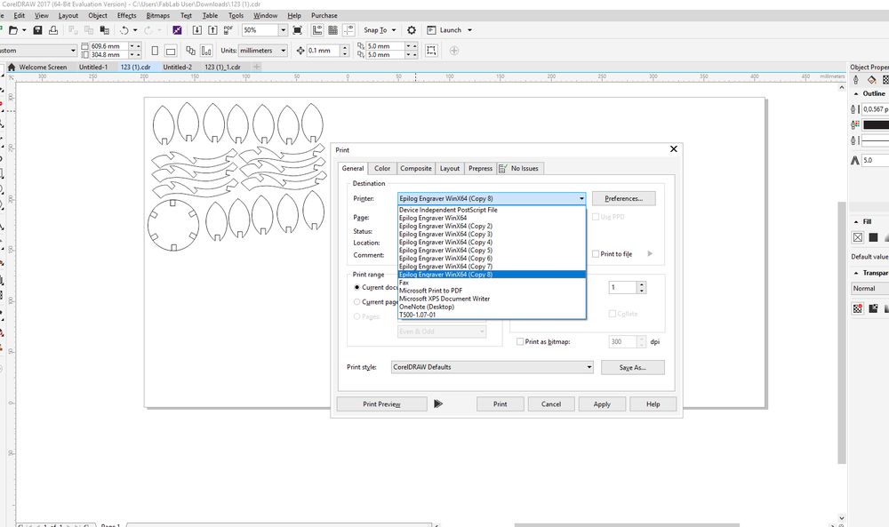
After all our file gets ready for printing, we need to set the printing parameter and environments. For that, after clicking Ctrl+P, and select the printer.
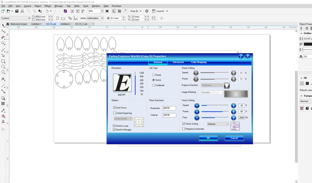
From the Preference option, we need to set the printing parameters. Set the Piece Size (mm) widthto 609.6mm and height of 304.8mm asit is the bed size of the laser machine that we are using.
From the Job Type, select the vector as I was having just cutting job and not printing. Than set the power and speed of the laser to cut my design.
In order for the good result, it is necessary to check the Auto Focus option as it will align the height of the laser head above the materials that we want to print on. Without auto focus, laser will not know where the material is and it will start to print from where it's head is leading to unfocused power to the material.
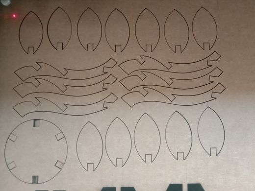
After the set up, I made a print on the laser. Cuts were clear and well cut due to my less speed and more power.
- Power and speed used for my cutting:
- Power 80%
- Speed 20% This is due to power deterioting of the laser machine. Actually the given power and speed to cut cardboard in the manual is:
- Power 45%
- Speed 20%
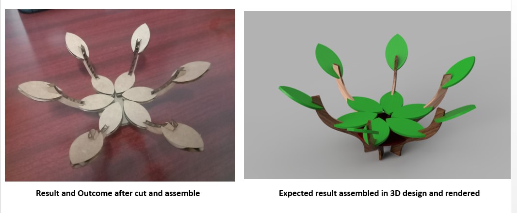
Result I got areas expected and satisfactory. This can contain fruits but as it is made of cardboard, it is weaker. And also need to add some more components as the space between two stems are further than expected.
Group Assignment find HERE.
Thank You
Reference
- You Tube video https://www.youtube.com/watch?v=CGeL6ot2mZ0
- Laser Design Idea: https://www.pinterest.com/rebeccau0194/laser-cutting/.
- Image for Vinyl Cut Download: https://za.pinterest.com/raymondjohngibb/op-art-and-optical-illusions/