PROJECT DEVELOPMENT
Step by step of this interesting journey.
Step by step of this interesting journey.
Complete your final project, tracking your progress
- what tasks have been completed, and what tasks remain?
- what's working? what's not?
- what questions need to be resolved?
- what will happen when?
- what have you learned?
I invite you to see the step by step of my final project, a compilation of knowledge and experiences applied to a final project.
The idea of design changed little by little, becoming more and more realistic around the technology and materials available.
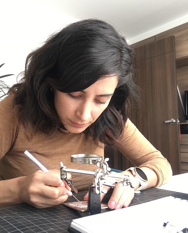
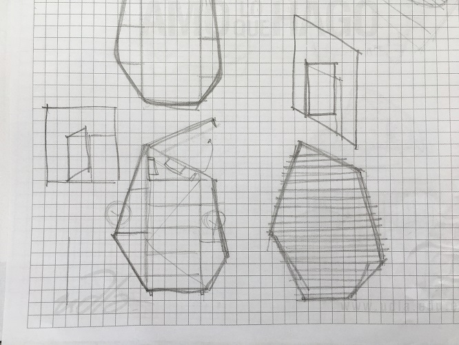
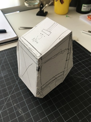
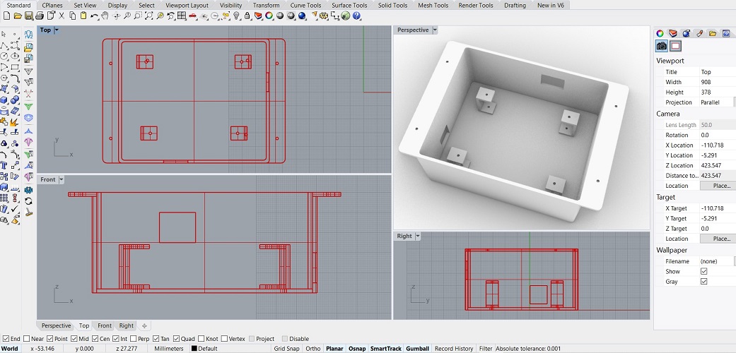
I decided to start with some sketches by testing shapes and analyzing suitable measurements for what I had in mind. Later I made a basic 3D model
using Rhino, however it was important for me to understand the object in a tangible model to analyze its shapes, cut, paste, scratch
(my designer mind takes me that way).
I made a first mockup by hand (just like in the old days) using cardboard, scissors and glue. It was very helpful in planning the scope of my project.
Obviously at the beginning I expected it to do a million things but with the spiral methodology, it became more realistic little by little.
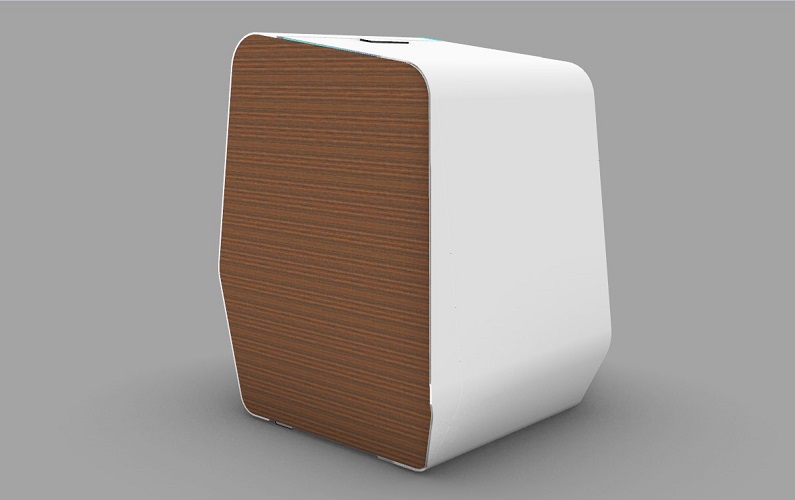
I modified the model in 3D and made a second model with cardboard and the laser cutter. The cardboard at this point still allowed me to make modifications,
scratch, cut, paste. This was the design I wanted to build for my final project.
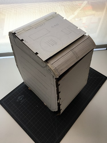
Again modifications in the 3D adapting the assemblies of the side covers, design the cover according to the components that were going to be used.
The third model already worked as my final external bin.Time to turn it real!
For laser cutting there ware two important determining factors to take into account, the thickness of the material and the format according to the capacity of the machine (60x40cm).
Fortunately, the larger pieces that are the side covers fit in the given format. I used 4mm mdf.
It was necessary to carry out a test with the texture that I wanted to engrave to try the flexibility of the material in the curved parts. For this, I made a section of
the case at a real scale and tested both the material properties and the cutting parameters.
| Test # | Min power (%) | Max power (% | Speed (mm/s) | Picture | Comments |
|---|---|---|---|---|---|
| 1 | 75 | X75 | 8 | 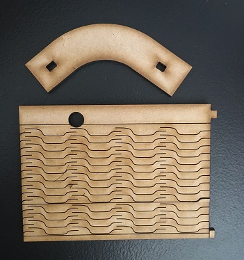 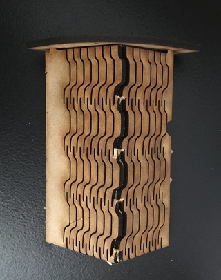
|
Looks nice, but is not flexible enough, as soon as I tryed to bend it, it broke |
| 2 | 77 | X77 | 8 | 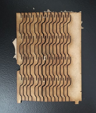 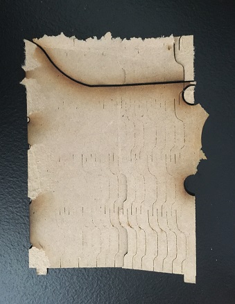
|
Not enough yet, it didn’t cut all the lines, (ignore those really black ones, those were from a previous work, I was re using some material left overs). It didn’t even cut the contour. |
| 3 | 77 | X77 | 6 | 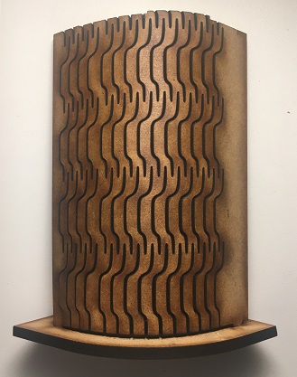
|
Works perfectly, these are the parameters I am going to use |
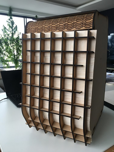
With the pieces ready, it was time to assemble them. Despite having done preliminary tests, my curved parts were not as flexible as expected. For this reason I decided to immerse them
in water for a few minutes (approximately 30) and use the side covers as support. One thing I didn't plan for was that wetting them would curl them but also increase their thickness.
For this reason I had to sand the support holes of the side covers for them to fit. Added some masking tape to support the center of the piece while it dryes over night.


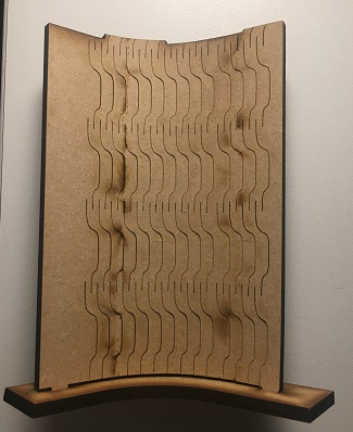
For the side cover I followed the same process, submerged it in water and placed it at 90 degrees against a wall with a weight on top so it can dry over night.
The next day I already had the necessary curvature. I joined it with the side covers and this is the result:


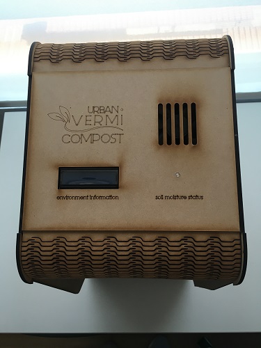
Next step, the design and production of the top cap. I made the design in illustrator taking into account the measurements of the components that I want to show, I engraved the logo and cut the rest of the piece.
The parameters I used for this piece are:
| Details | Min power (%) | Max power (% | Speed (mm/s) |
|---|---|---|---|
| Engrave | 20 | 20 | 40 |
| Cut | 77 | 77 | 6 |

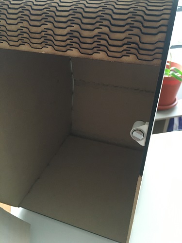
It was important to protect my board and its components from possible splashes of water, as well as to contain the cables in one place.
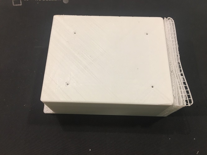
The design is planned to accommodate the protection case at the back of the bin, in the curvature. For this I designed a box with lateral
perforations through which the power cables and the sensors and actuator's cables will come out. I added some perforated side tabs to screw
this box to the external bin.
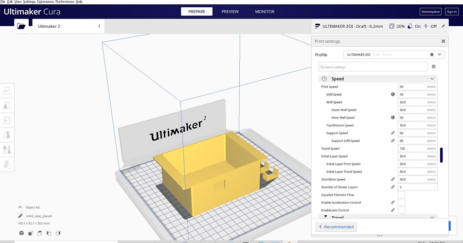
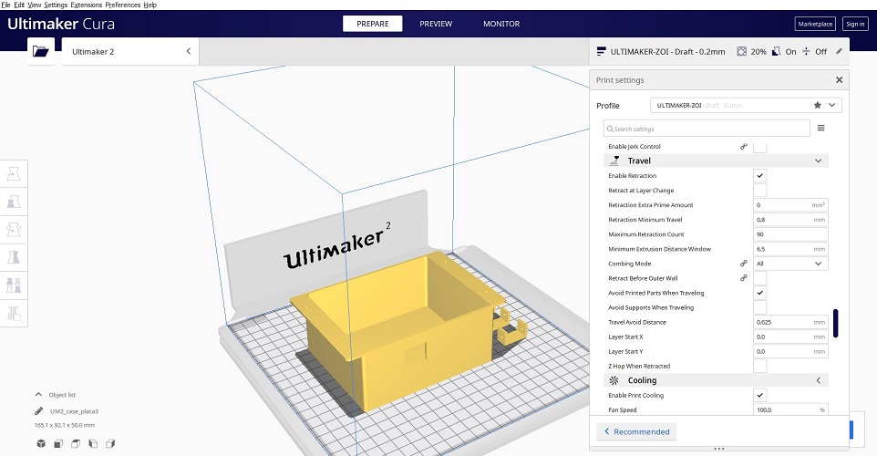
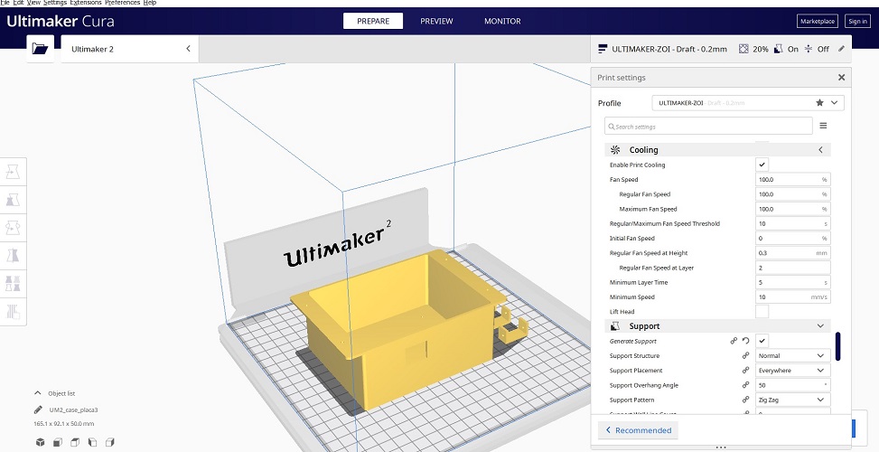
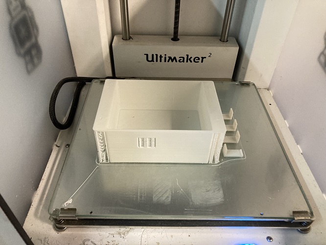
To print this piece I used the Ultimaker 2 with the following parameters, the process lasted around 8 hours.
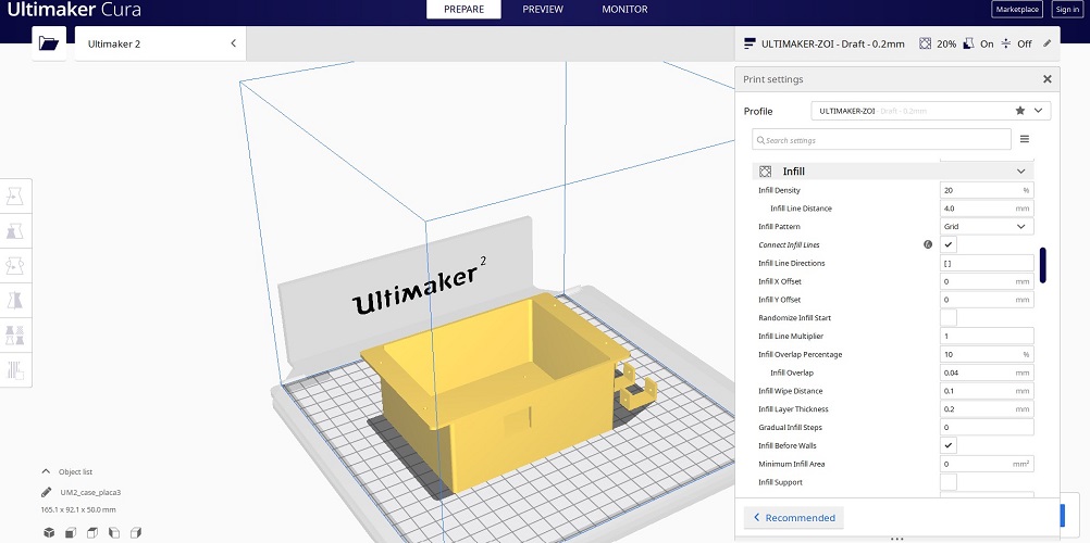
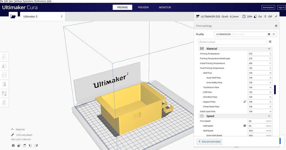
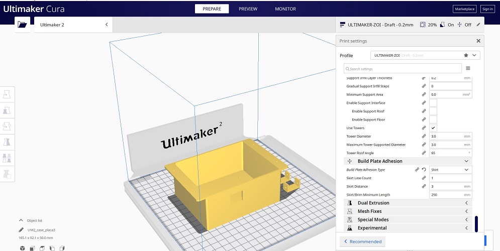
This is the result, the bridges were easy to remove.
As part of wild card week, I had planned to do a layer-by-layer process with sheets of balsa wood. Initially it was a process discussed with my tutor,
but after doing it, it seems that I did not meet the requirements of that week.
Anyway, I decided to continue with what was planned to test an alternative
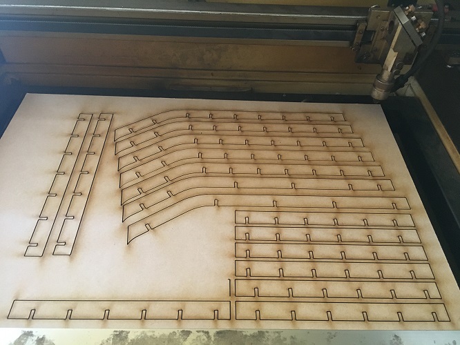
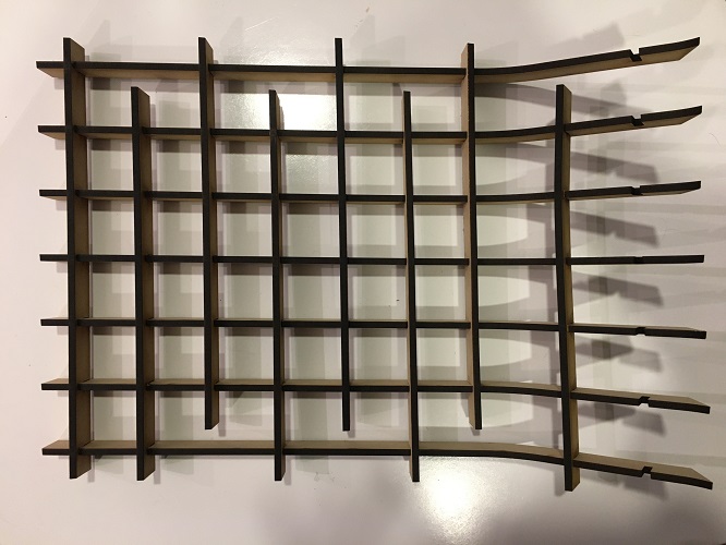
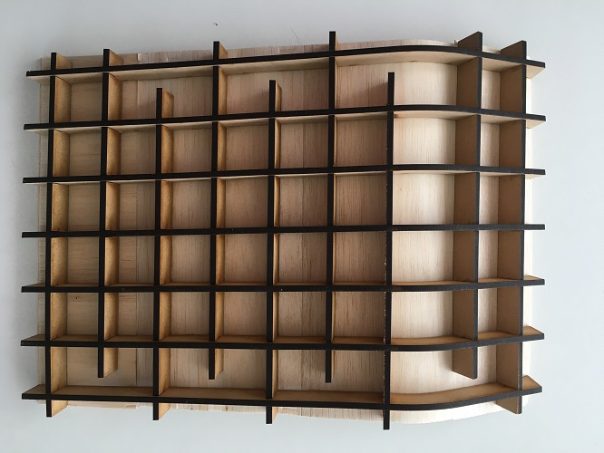
to wood bending that could be interesting in future projects. For this, I made a base structure that supports the wood sheets, it had to have some relationship
with the exterior case, for which I made interlocking slats that allowed to maintain this curvature of the front door.
I used the laser cutter for these slats and assembled them using a rubber mallet.
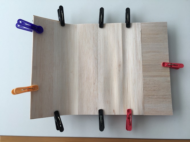
The next step was to cut the sheets of wood to the required size and glue them one by one using carpentry glue, which was dissolved with water in a 2:1 relation
so that the humidity allows the sheets to bend easily. I held the pieces with clamps and let it dry overnight. When removing the clamps, this was the result:
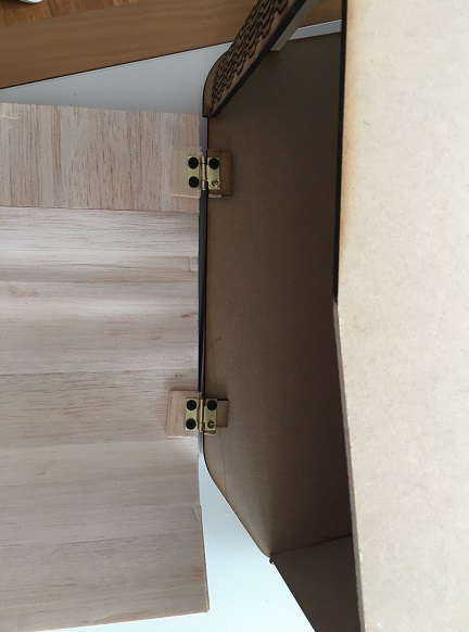
To install it in the external bin, I used small metal hinges that can be found in any hardware store and that can be adjusted with small screws.
I also added a magnetic stop that will keep the door closed.
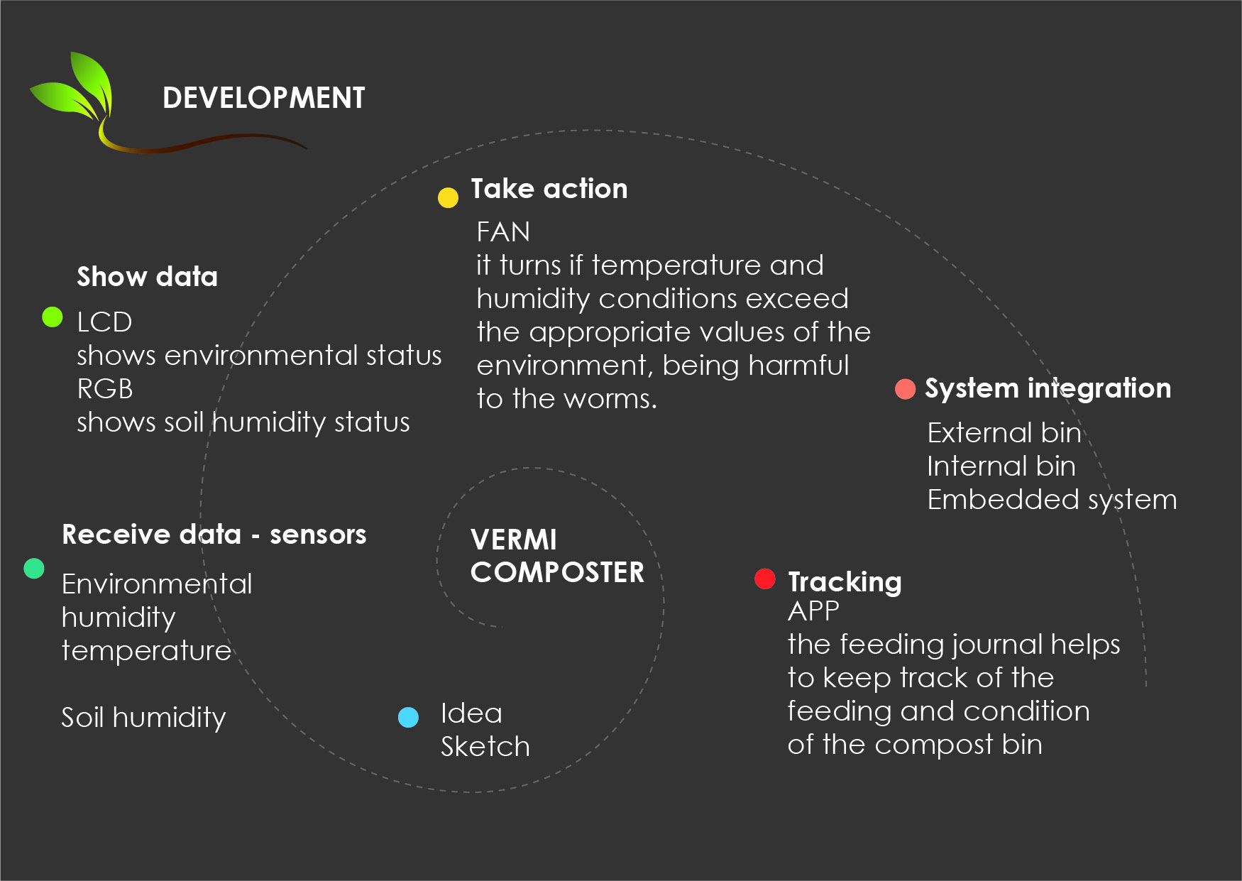
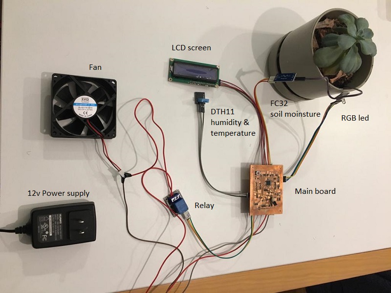
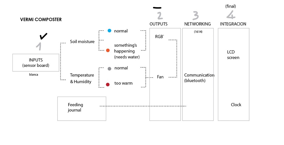
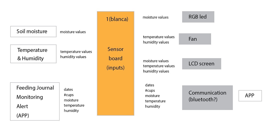
The following diagram shows how the systems should work.
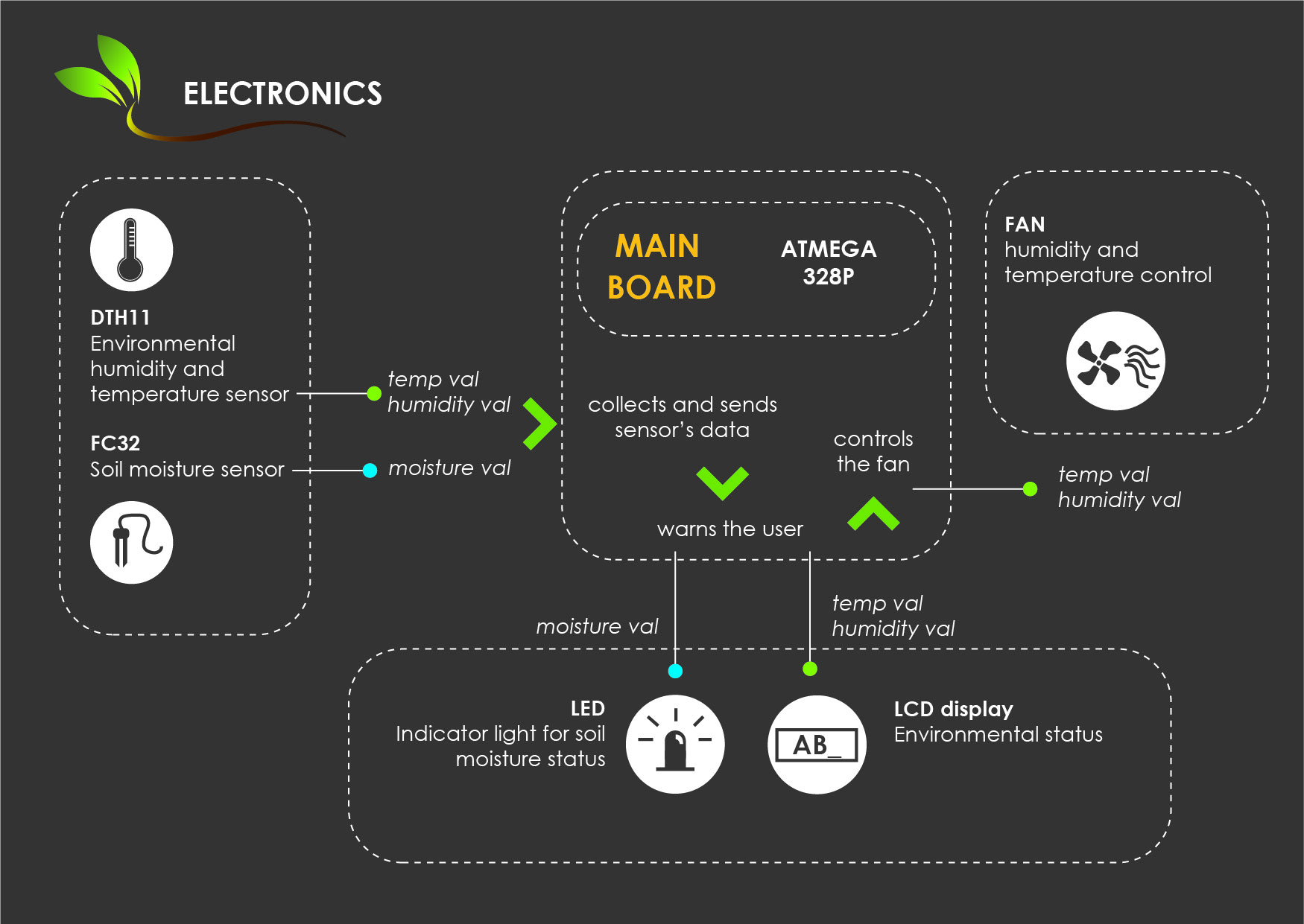
There are two sensors that must be integrated into the system. The first one, the soil moisture sensor, takes these values and has two options that will be
displayed on the rgb led: red and green, if the parameters are within 80% which is adequate to maintain a healthy life of the worms, then the green light
will be displayed. The moment this light turns red means that the soil is dry and needs watering.
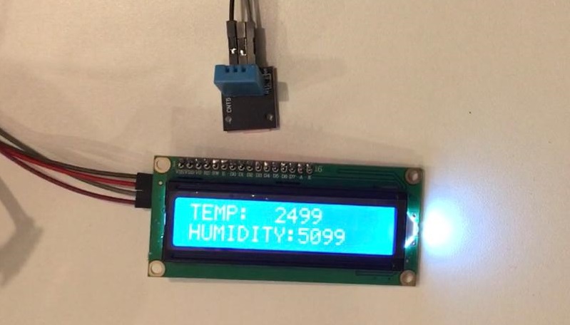
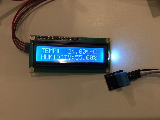
The second Dht11 sensor measures the temperature and humidity status of the environment and is constantly sending this data to the LCD screen.
Temperature is measured in Celsius degrees and humidity in%. It is important to differentiate between the humidity of the soil and the environment,
it is not the same, since the soil retains more humidity due to the work that worms do when processing organic waste and that it generates its own humidity.
If the ambient temperature is too high, it can affect the life of the worms in the compost bin. In case of exceeding 35 degrees the fan will automatically turn on,
when it returns to regular temperature (less than 35C) the fan will turn off. It also turns on if the humidity exceeds the limits which is 90%.
Also, remains a possibility in the future for the compost bin to send data to the feeding diary via bluetooth, to complement the monitoring of the life
of the worms in the application, so far you can just write information about its status by yourself.
Base my design on the boards created in the weeks of inputs and outputs
where you can find more details.Also, files can be found at the end of this document.
This is the schematic and board design I used for my board, made on EAGLE.
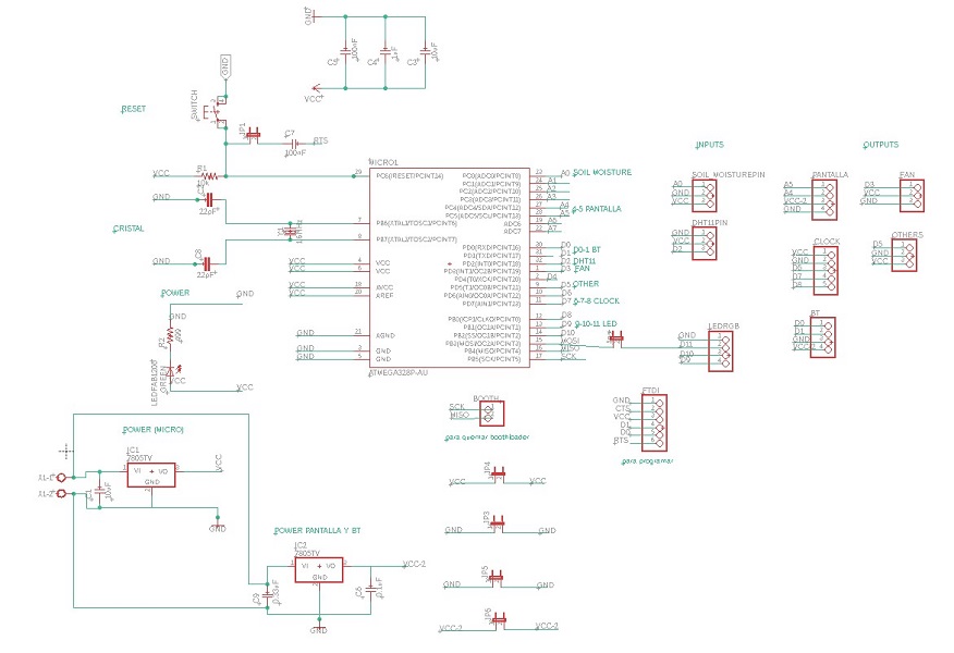

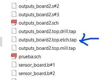
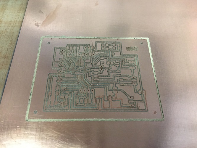
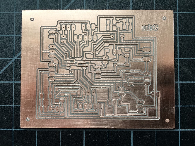
The next step is the production of the board. These files will be available at the end of this document.
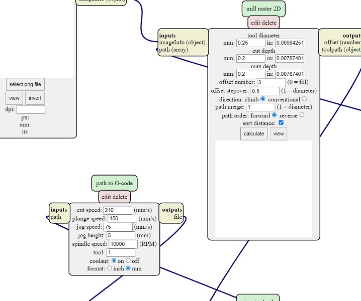
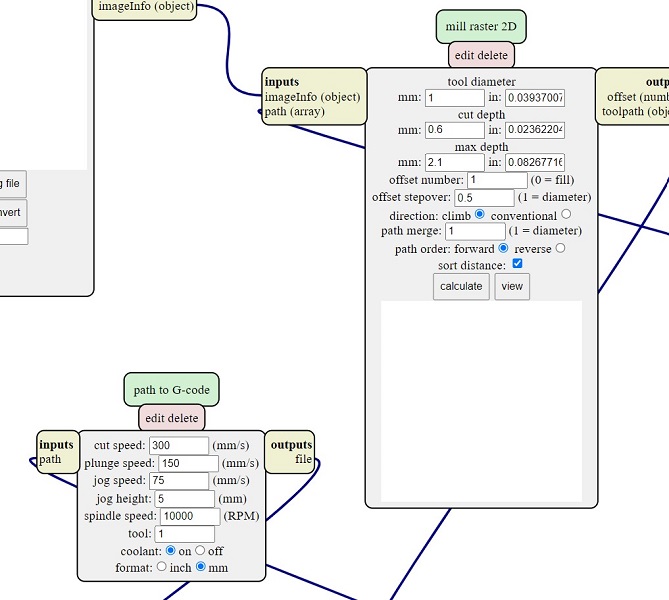
I used 3 different codes and these are the parameters I used:
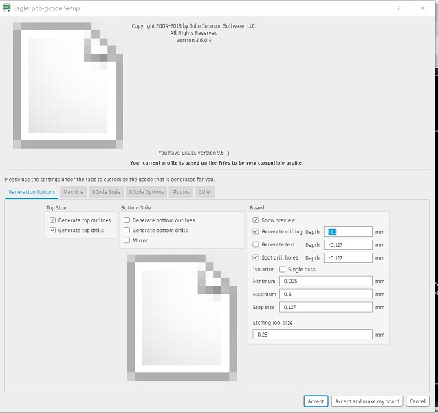
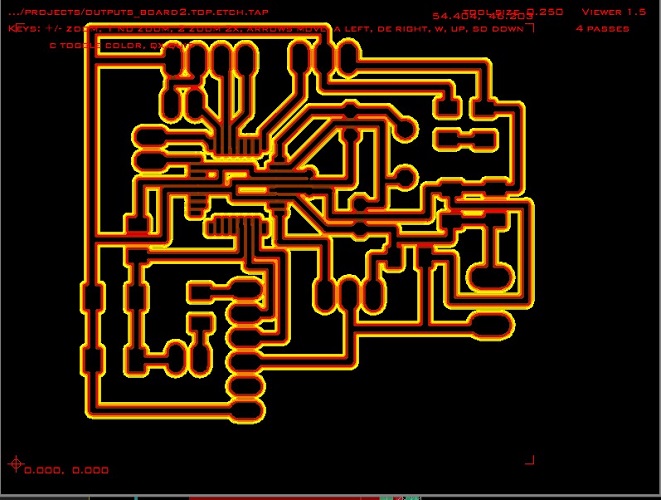
This is the result, for further information of the worflow of the cnc milling machine for electronic boards you can check my electronics design week
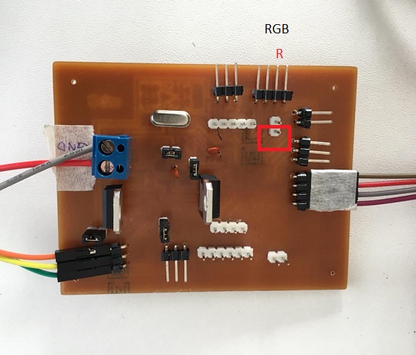
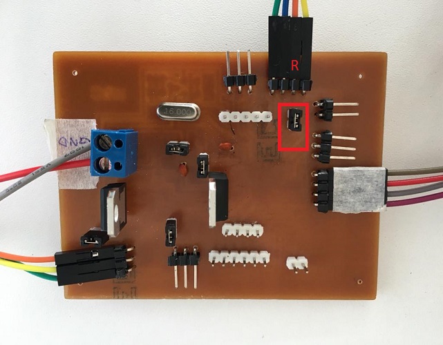
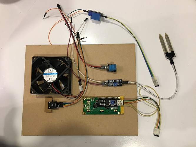
Next, I soldered the components. Here you can find the detail:
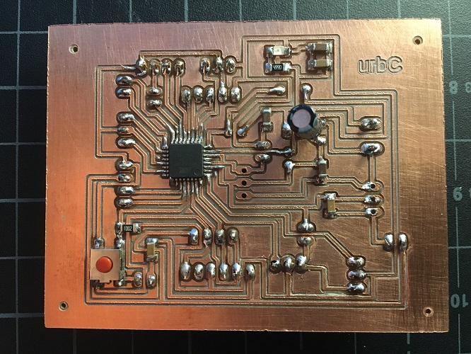
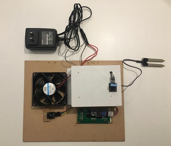
First make all the connections, soil humidity sensor, humidity and ambient temperature sensor (inputs), RGB led, screen and fan (outputs).
To power the system use an external 12V source.
This part was the most challenging for me. Diego helped my a lot troughout the process, to understand and generate my own code.
To program the board I used the programmer developed in the electronics produccion week, the FabATinyISP,
which can be programmed via their SPI ports in conjunction with the RESET pin, using a SPI protocol. The 6 pins needed are:
MISO, SCK, RST, VCC, MOSI, GND. Data is sent in series, this means there is a serial communication protocol.
I used Arduino IDE to create the code which you can download at the bottom of this site.
//-- Libreries
#include //DHT and LCD libraries
#include
//-- Pins LCD and sensor
#define I2C_ADDR 0x27
#define BACKLIGHT_PIN 3
#define En_pin 2
#define Rw_pin 1
#define Rs_pin 0
#define D4_pin 4
#define D5_pin 5
#define D6_pin 6
#define D7_pin 7
#define DHT11_PIN 2 //Declaring where the DHT signal pin is wired
//-- LCD functions
LiquidCrystal_I2C lcd(I2C_ADDR, En_pin, Rw_pin, Rs_pin, D4_pin, D5_pin, D6_pin, D7_pin);
//-- Environment sensor functions
dht DHT; //Declaring the DHT as a dht type to use it later
//-- LED pins declaration
int redpin = 11; //select the pin for the red LED
int bluepin = 10; // select the pin for the blue LED
int greenpin = 9; // select the pin for the green LED
//--FC32 pin declaration - soil moisture
int msensor = A0;
//--FAN pin declaration
int fan = 3;
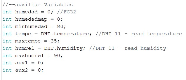
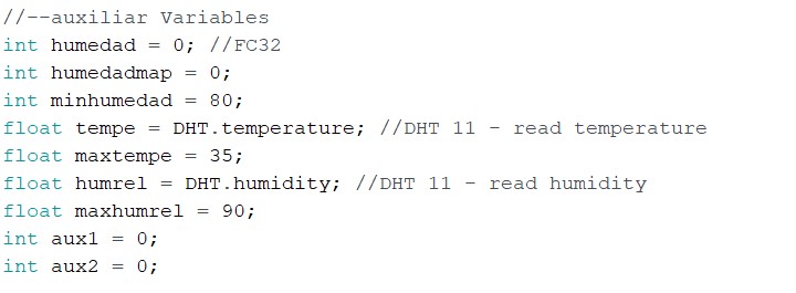
//--auxiliar Variables
int humedad = 0; //FC32
int humedadmap = 0;
int minhumedad = 80;
float tempe = DHT.temperature; //DHT 11 - read temperature
float maxtempe = 35;
float humrel = DHT.humidity; //DHT 11 - read humidity
float maxhumrel = 90;
int aux1 = 0;
int aux2 = 0;
// initial configuracion
void setup() {
Serial.begin(9600);
// for led
pinMode(redpin, OUTPUT);
pinMode(bluepin, OUTPUT);
pinMode(greenpin, OUTPUT);
// for screen
lcd.begin (16, 2);
lcd.setBacklightPin(BACKLIGHT_PIN, POSITIVE);
lcd.setBacklight(HIGH); //Lighting backlight
lcd.home ();
// for fan
pinMode(fan, OUTPUT);
digitalWrite (fan, LOW);
}
// what is gooing to be done
void loop() {
//LEER VALORES
//FC32
humedad = analogRead(msensor);
humedadmap = map(humedad, 550, 10, 0 , 100); //hace regla de 3
/*
Serial.print("Humedad: ");
Serial.print (humedad);
Serial.println("% ");
delay (1000);
*/
//DTH11
int chk = DHT.read11(DHT11_PIN);
tempe = DHT.temperature;
humrel = DHT.humidity;
/*
Serial.print("Tem= ");
Serial.println(DHT.temperature);
Serial.print("Humidity= ");
Serial.println(DHT.humidity);
delay(1000);
*/
//FC32 compare
if (humedadmap <= minhumedad)
{
digitalWrite(redpin, HIGH);
digitalWrite(greenpin, LOW);
digitalWrite(bluepin, LOW);
delay(500);
}
else {
// if ((humedadmap >= 0) && (humedadmap < minhumedad))
digitalWrite(redpin, LOW);
digitalWrite(greenpin, HIGH);
digitalWrite(bluepin, LOW);
delay(500);
}
//SEND DHT11 VALUES TO LCD
lcd.setCursor(0, 0); //Setting the position where you want to start writing the message (0,0) is top left
lcd.print("TEMP:"); //Message to display
lcd.setCursor(7, 0); //Start writing on the position (7,1)
lcd.print(tempe);
lcd.println(" C ");
lcd.setCursor(0, 1); //Setting the position where you want to start writing the message (0,0) is top left
lcd.print("HUMIDITY:"); //Message to display
lcd.setCursor(9, 1); //Start writing on the position (9,1)
lcd.print(humrel);
lcd.println("% ");
delay(4000); //Display time
// DHT11 compare - ACTIVATE FAN
if ((tempe >= maxtempe) || (humrel >= maxhumrel))
{
digitalWrite(fan, HIGH);
delay(3000);
}
if ((tempe < maxtempe) || (humrel < maxhumrel))
{
digitalWrite(fan, LOW);
delay(3000);
}
}
This video shows the final result, all systems working together!. Sensors react to external stimuli of humidity and temperature, screen is showing values, the led is reacting to soil humidity
and the fan is turning on and off depending on the humidity and temperature values permitted.
Once I uploaded the code, and start trying the system, a couple of things came up.
I want an application where you can keep a constant record of the state of the compost bin. For this I based my design in this tutorial
How to make a diary and
app inventor to create it, added my project logo and you can write information about the
compost bin, how much you fed the worms, when and all the observations you have about your system.
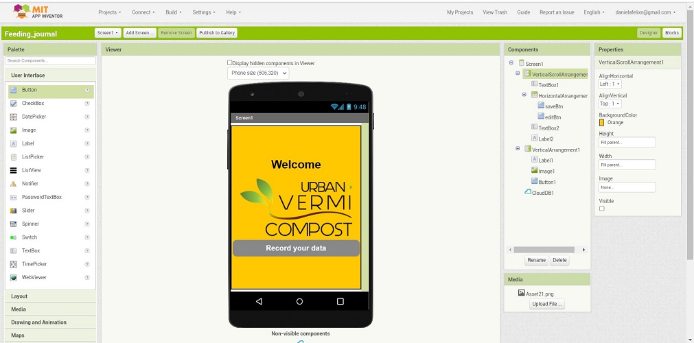
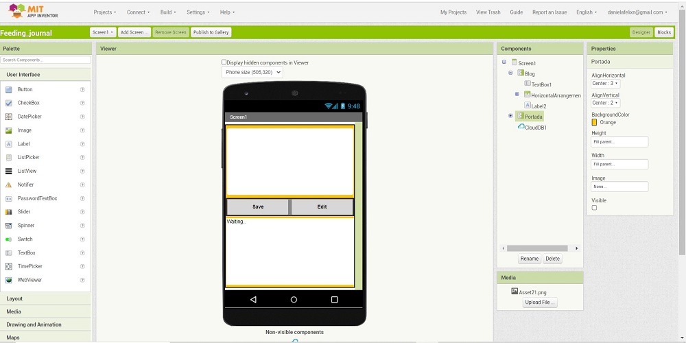

This is the final result, you can download it to you phone and have it avaliable all the time.
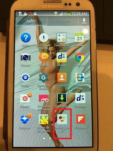
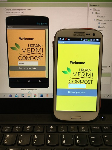
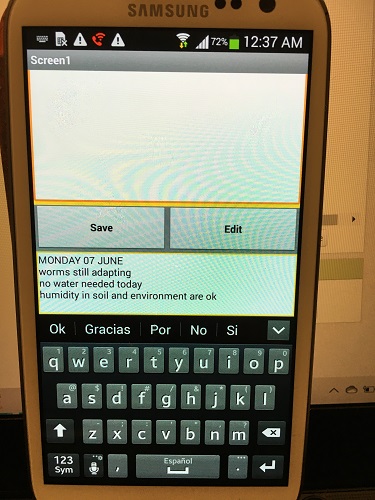
Here you can download the .apk file of this app to try it yourself.
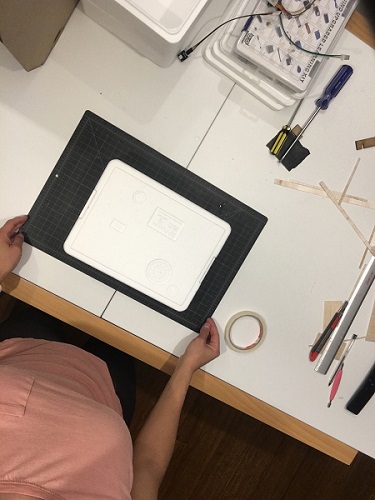
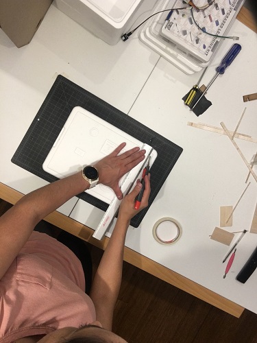
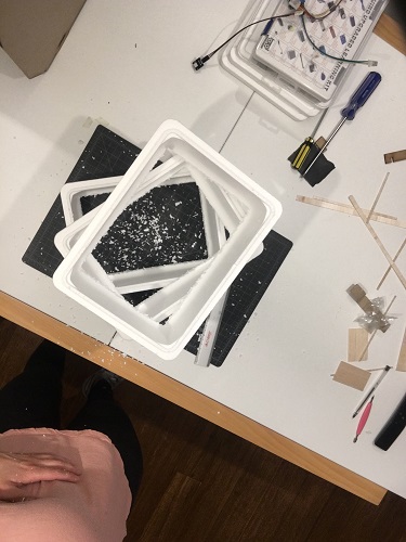
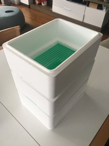
This step is designed to be able to adapt to any low cost material, even any container which is already avaliable at home (there are many tutorials that shows hoe to do DIY composters).
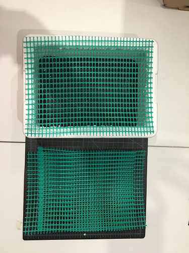
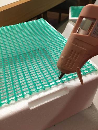
In this case I have used 3 Polystyrene containers (avaliable at a local harware store - really cheap), remove the base and glue a perforated mesh of at least
0.5x0.5 cm so that the worms can move from one tray to another. To glue the mesh I have used hot silicone. They can be applied one on top of the other and it
is recommended to leave an additional one at the base to collect the liquid waste known as liquid humus that has a high nutritional value.
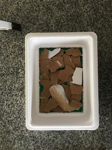
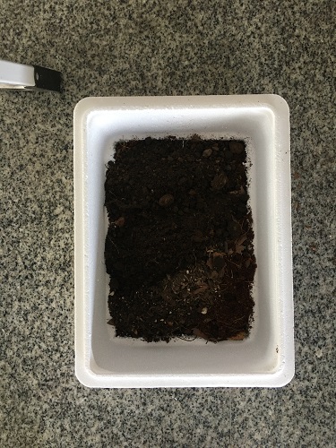
In order for the compost bin to be a pleasant home for worms, it must be prepared. Place a layer of cardboard on the base (it can be recycled, I used the lid of a pizza box),
add the soil (it does not need to be of good quality since the worms will be in charge of transforming it into soil with a high nutritional level).
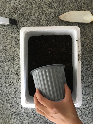
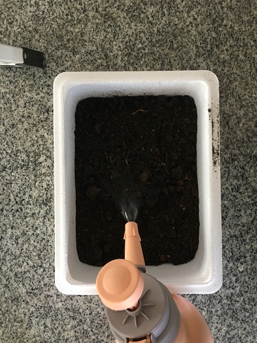
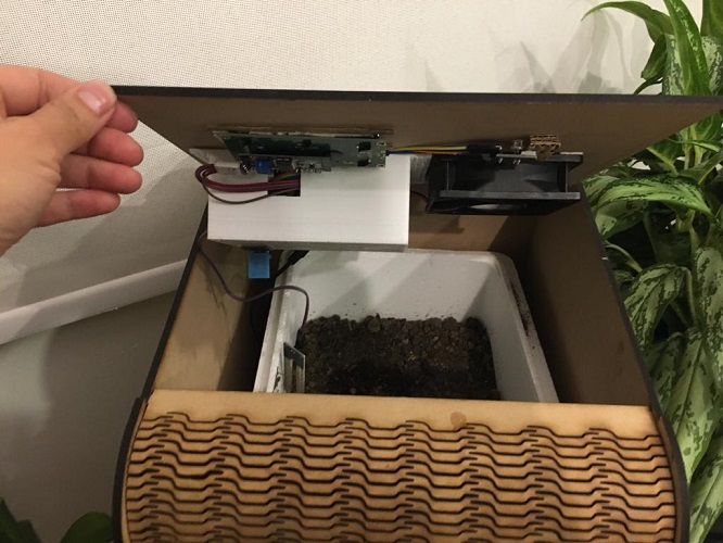
At this time the separate parts are ready. I placed the bin inside, connected the sensors to the board, it's time to see how the system works.
On the lid there are all the modules for the user to interact. They are placed and contained in the board protection case.
Once installed on the external bin it looks like this:
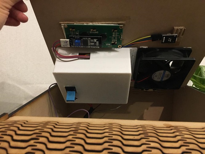
Everything is ready!! time to try if it works, I connect the power and this is what happened.
Great! it is working! I'll keep track of my vermicomposter and also add this information to my journal app.
These are the files from my final project:
In planning my project I have designated at least 3 weeks for its execution. It has been a very intense and stressful three weeks, combined with work and lockdown
restrictions.
It's been interesting to see how so many decisions are made in the manufacturing process. The initial idea was very ambitious and as I progressed through the
process I understood the spiral methodology, starting small and moving forward as the project develops.
I started very conservatively, making small-scale models using thick paper and cardboard, which allowed me to land my design ideas.
During the process I had to make corrections in the design, constant trial and error, cuts, scraps, arrangements, paste, re-cut, redraw, review previous notes,
sleep dreaming of possible solutions. I really enjoyed the manual process, it was fun and entertaining to build things.
The most frustrating part for me has been the electronics, I am very excited to see that the sensors and actuators work but in the production of the board,
many errors that are difficult and very tedious to correct tend to be generated. In addition to being my weakest field, programming has cost me a lot,
it is a language that is difficult for me to unify in order for all systems work, one moment they work perfectly, the next I am looking for a solution on
YouTube and forums, which becomes frustrating when the final delivery time is approaching minute by minute.
During the weekly assignments I wanted to test the techniques to develop products that were not related to my final project and I focused on testing and
experimentation projects. This meant that in the end I had to develop everything, which involved additional time and effort. To my past self, I would
recommend focusing on the final project from the beginning and follow a programming course.
I would love to develop new things and spend some extra time applying all these skills, but I found out that working and studying at the same time is not an
easy task.