Electronic designs typically contain a selection of highly complex functions—such
as processors, controllers, and memory—interfaced to each other by a plethora of
simple functions such as primitive logic gates. The simple interfacing functions
are often referred to as the glue logic because they “glue” everything together.
CHECK LIST
Group assignment
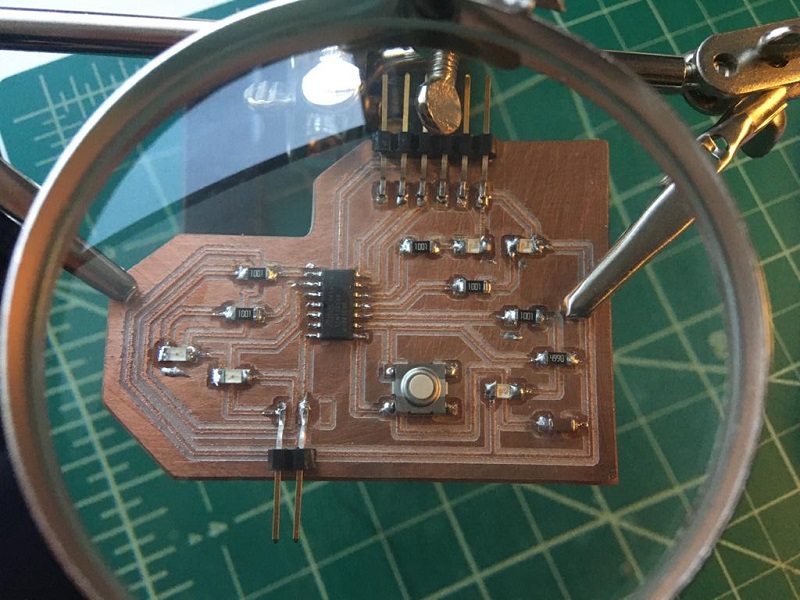
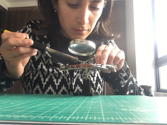
Use the test equipment in your lab to observe the operation of a
microcontroller circuit board (in minimum, check operating voltage
on the board with multimeter or voltmeter and use oscilloscope to
check noise of operating voltage and interpret a data signal)
Document your work (in a group or individually)
Individual assignments
Redraw one of the echo hello-world boards or something equivalent,
add (at least) a button and LED (with current-limiting resistor) or
equivalent input and output, check the design rules, make it, test it.
GROUP ASSIGNMENT
Find out the details of our common work al ZOI
Here.
OSCILLOSCOPOE
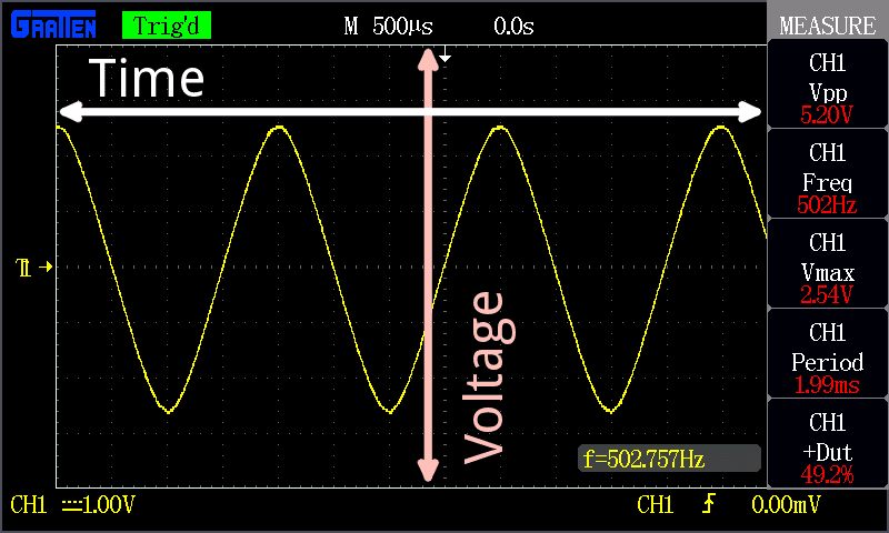
Oscilloscopes (or scopes) display voltage signals as waveforms,
visual representations of the variation of voltage over time. The signals are plotted on
a graph, which shows how the signal changes. The vertical (Y) access represents the
voltage magnitude and the horizontal (X) axis represents time.
The graph on an oscilloscope can reveal important information:
Voltage signal shape when operating as intended
Current signal shape when using a current clamp suitable for using on an oscilloscope
Signal anomalies
Amplitude modulation of an oscillating signal and any variations in frequency
Whether a signal includes noise and changes to the noise
For this task we used
For more information about how to use a oscilloscope you can go to this website.
Click Here.
Multimeter
A digital multimeter is a test tool used to measure two or more electrical values—principally
voltage (volts), current (amps) and resistance (ohms). It is a standard diagnostic tool for
technicians in the electrical/electronic industries.
For his task I used an auto-range digital multimeter which has multiple functions:
DC voltage measuring (auto ranging)
AC voltage measuring (auto ranging)
DC current measuring
AC currente measuring
Temperature measuring
Resistance measuring
Capacitance measuring
Diode testing
Transistor testing
Audible continuity testing
In this case I needed the contiuity test, but first needed to understand the basic concepts.
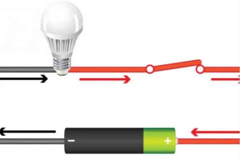
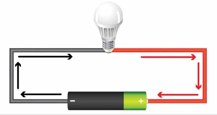
Continuity is the presence of a complete path for current flow. A circuit is complete when its switch is closed.
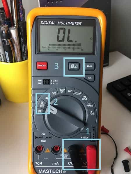
There are 3 steps to set the multimeter to test continuity:
Connect the black test lead to the COM jack and the red test lead to the V/Ω jack. NOTE: the polarity of red test lead connection is possitive "+"
Set the function swith to position and push the V/ button
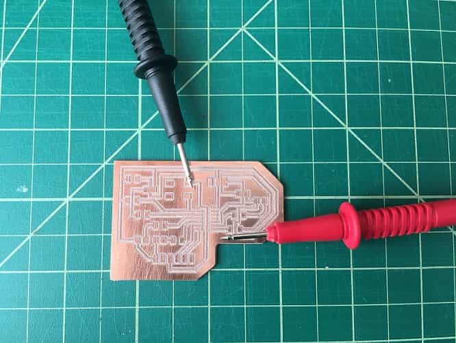
Connect test leads to two point of the cirucuit under measurement. If continuity exist
(for example, the resistance is lower than 30Ω) the built-in buzzer will sound.
Continuity testing overview
A digital multimeter’s Continuity Test mode can be used to test switches, fuses, electrical connections, conductors and other components. A good fuse, for example, should have continuity.
A DMM emits an audible response (a beep) when it detects a complete path.
The beep, an audible indicator, permits technicians to focus on testing procedures without looking at the multimeter display.
When testing for continuity, a multimeter beeps based on the resistance of the component being tested. That resistance is determined by the range setting of the multimeter. Examples:
If the range is set to 400.0 Ω, a multimeter typically beeps if the component has a resistance of 40 Ω or less.
If the range is set 4.000 kΩ, a multimeter typically beeps if the component has a resistance of 200 Ω or less.
The lowest range setting should be used when testing circuit components that should have low-resistance value such as electrical connections or switch contacts.Continuity is the presence of a complete path for current flow. A circuit is complete when its switch is closed.
For more information about how to use a multimeter you can go to this website.
Click Here.
I used the multimeter to check the traces on my board and the polarity of the leds I used.
BUILDING A HELLO WORLD
It might be something obvious for many people, but I don't really know
what a hello world is.
A "Hello, World!" program generally is a computer program that outputs or
displays the message "Hello, World!". Such a program is very simple in
most programming languages, and is often used to illustrate the basic
syntax of a programming language. It is often the first program written
by people learning to code. It can also be used as a sanity test to make
sure that a computer language is correctly installed, and that the
operator understands how to use it.
basic concepts
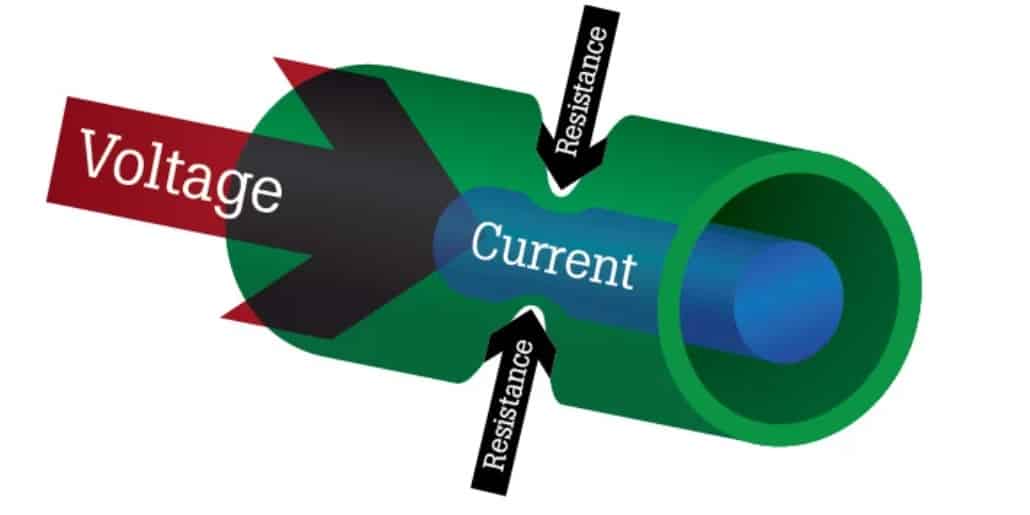
Electric current:
is the rate at which electrons flow past a point in a complete electrical circuit. At its most basic, current = flow.
"Es la cantidad de electricidad que recorre un conductor"
Voltage: is the pressure from an electrical circuit's power
source that pushes charged electrons (current) through a conducting loop,
enabling them to do work such as illuminating a light.
"Es la fuerza que genera la corriente."
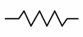
Resistance:
is a measure of the opposition to current flow in an electrical circuit,
measured in ohms, symbolized by Ω.
"Es la oposición a la corriente que presenta un material, componente o circuito."
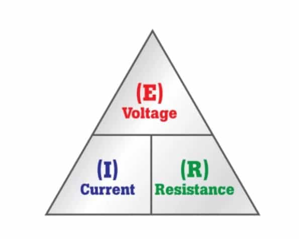
Ohms law:
is a formula used to calculate the relationship between voltage, current and resistance in an electrical circuit.
E = I x R
voltage = current x resistance, or volts = amps x ohms, or V = A x Ω.
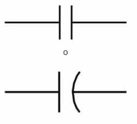
Capacitor: is a tool consisting of two conductive plates, each of which hosts an
opposite charge. These plates are separated by a dielectric or other form of insulator, which helps them maintain an electric charge.
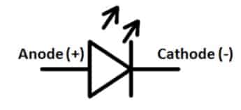
LED: light-emitting diode: a semiconductor diode that emits light when conducting current and is used in electronic displays, indoor and outdoor lighting, etc.
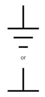
GND: ground or earth is the reference point in an electrical circuit from which voltages are measured, a common return path for electric current, or a direct physical connection to the earth.
You can place the black point (-) of the multimeter to ground and the red point to VCC (+)
in a loaded circuit to measure voltage.
VCC: (Common Collector Voltage) is the positive supply voltage for an integrated circuit
Found this interesting web site which describes and explains the function of the basic electronic components.Also, the pictures used for this basic concepts were taken from this sites: Definiciones de componentes electrónicos.
Also this complete guide from Fab Academy Electronics design.
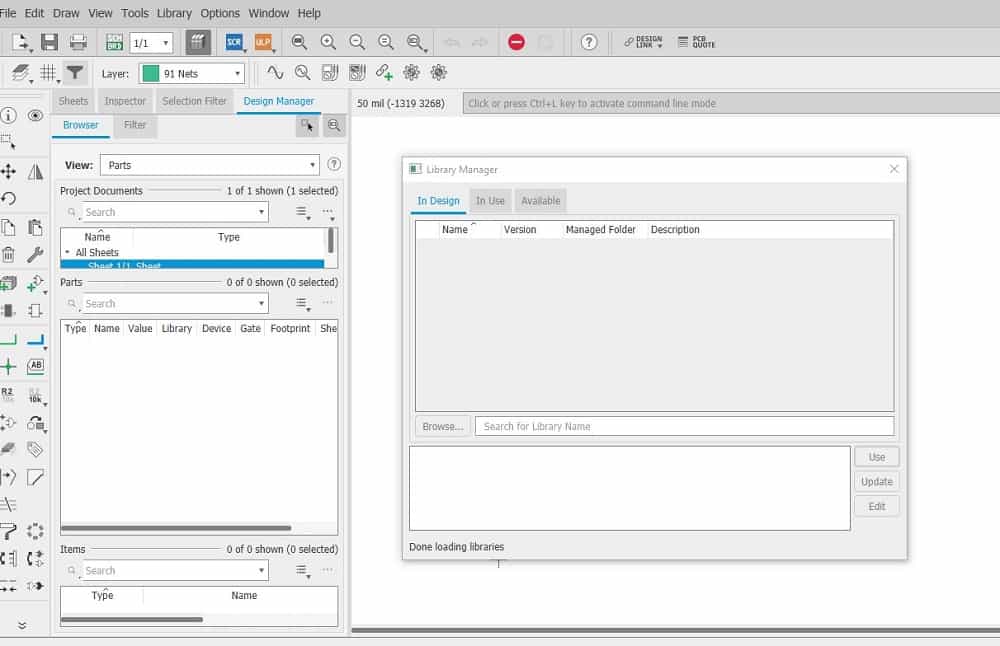
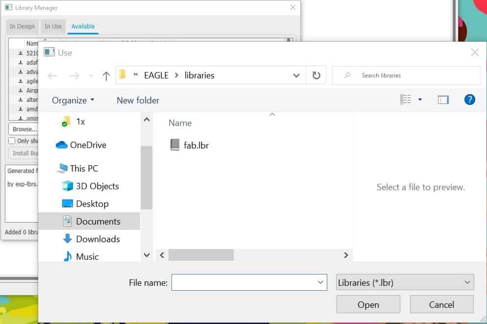
To download eagle and instal the fab component library you can go to my
pre fab page and fllow the instructions at the Electronics design section.
For this week assignment I designed a board based on
Adrian's Hello Train
from last year. I find this assignment pretty hard to do from scratch so I ratter follow
instrcutions until I understand all the concepts and processes involved.
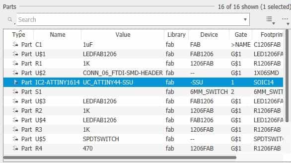
I checked his BOM which has the following components and started from there since
I already understand how to insert and connect them on Eagle:
1 - Attiny 1614
1 - Capacitor 1 µF
1 - Button
5 - Resistance 1k
1 - Resistance 499Ω
1 - 2x1 Pin
1 - 6x1 Pin
3 - Led (white) / There weren't avaliable at the lab inventory so I used blue leds
2 - Led (red)
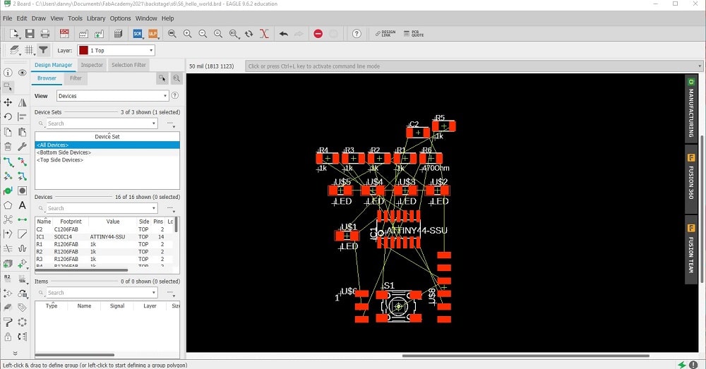
schematic
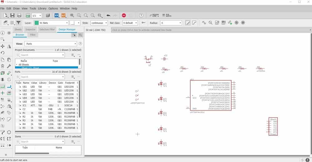
To start with the schematic I inserted the components from the fab library and checked the avaliability on the lab's inventory
to make sure I have all the components to built it later.
Found most of them but got really confused with the Attiny since I only found the Attiny 44, but on Adrian's
page he suggest the Attiny1614. I decided to go with it despite this condition. I wasn't really sure
that what I was doing would work but still wanted to do it to remind myself the process.
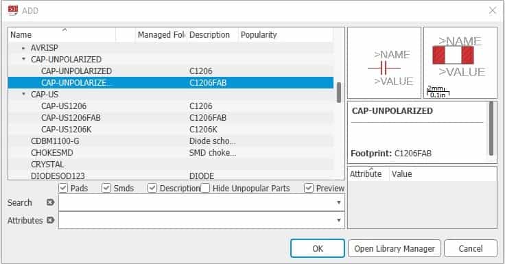
To upload the components write add or go to the "add component" icon located on the left bar.
With the components ready I wired them using labels to name them and add values to resitances.
This is the result:
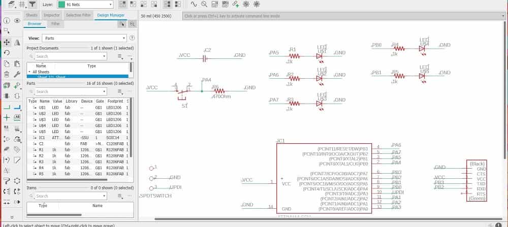
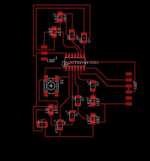
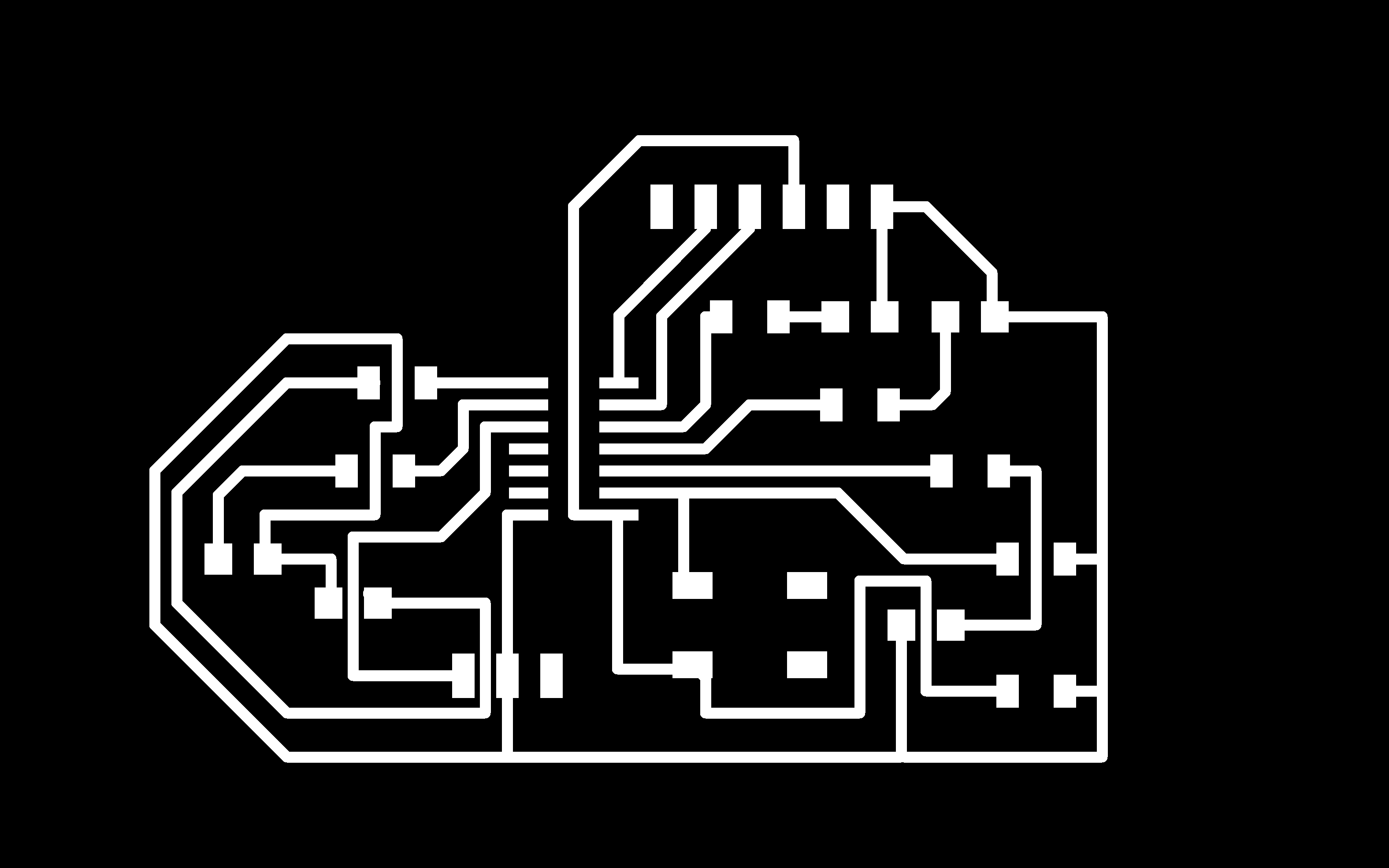
THE BOARD
Now is time to arrange the components on the board. Once on this window, all the components are placed in no
specific order. There are some things to have on mind for this step:
Yellow lines shows the connection between components
Make sure you are on the top layer unless you have components through the board, in that case you can alternate on the bottom layer also
Check the thickness of the traces, (used 24 for this board) if they are too thin they might be too delicate when you mill your board or
if they are too thick they might not fit within components
If you have an specific design on mind, place the main components where you want them to be and then connect the rest
Check the desing rules avaliable on Eagle configuration window.
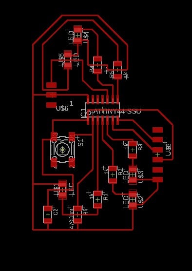
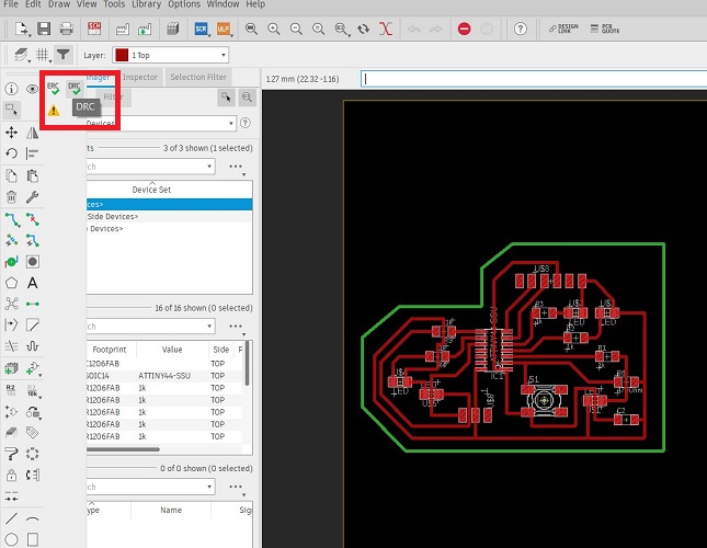
I enjoy arranging the components on the board. Once you are done you can check if there are errors.
For this go to "errors" located on the left bar with an attention symbol!. Luckily for me there were no errors.
CHANGING TRACE WIDHT
In case you have the traces made but for some reason you need to change the width, you can leave
the traces layer on, select all of them, on the text bar write down change width 24 (or the width you need),
press enter, right click on the drawing and change group.
MOVE ALL THE COMPONENTS AT ONCE
Make sure all the layers are on, select them, in the text bar write move, press enter, right click,
move group.
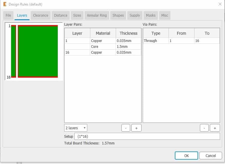
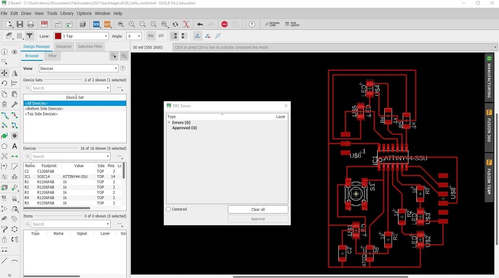
DESIGN RULES
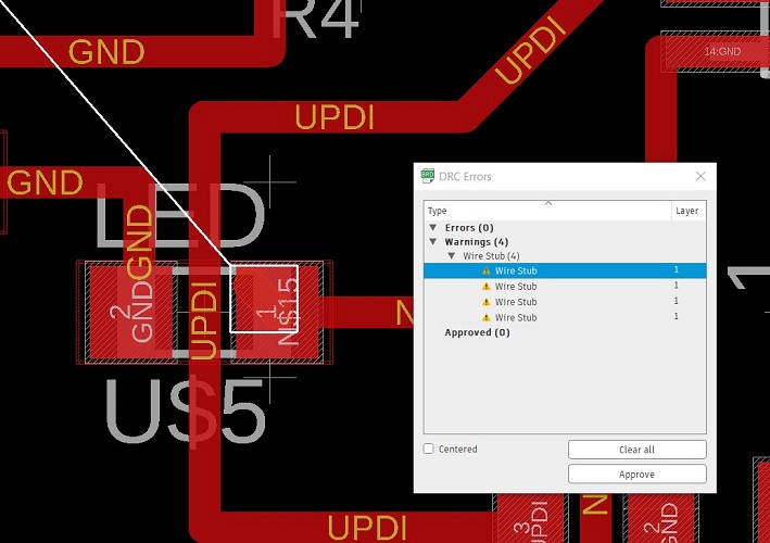
Eagle has an interesting option called DRC (design rule check) which warns you about clearance and design issues that could affect your board production.
In this case, based on the milling tool that will be used I set 0.4mm to make sure I wont have trouble later.
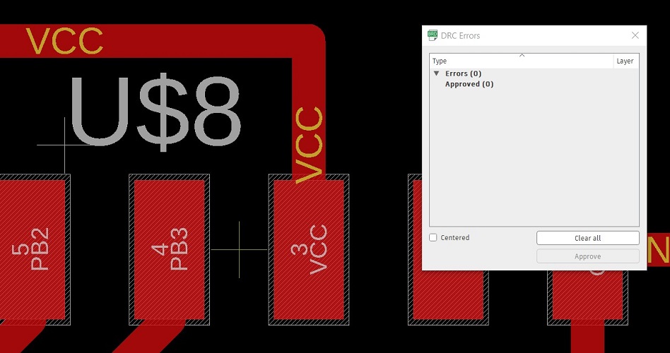
Also, if you press check, this window will pop up and some errors will be evident, in this case I had some trouble wiring, specially with double wires, errase the ones that are
not necessary or wire them again. Once this errors are cleared, the window will show 0 errors.
Here you can download the Design Rules Check File
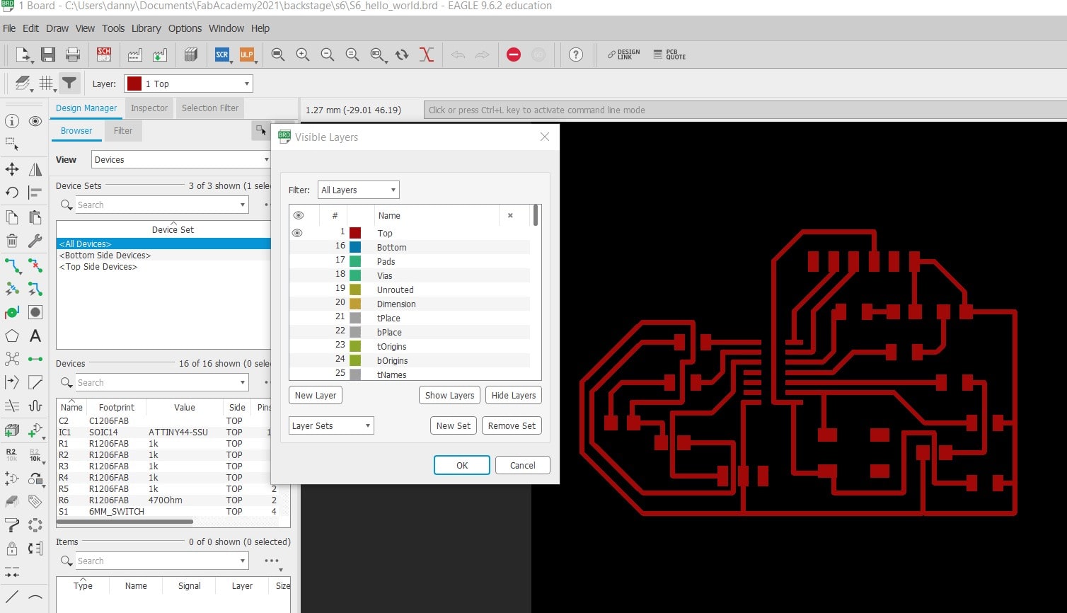
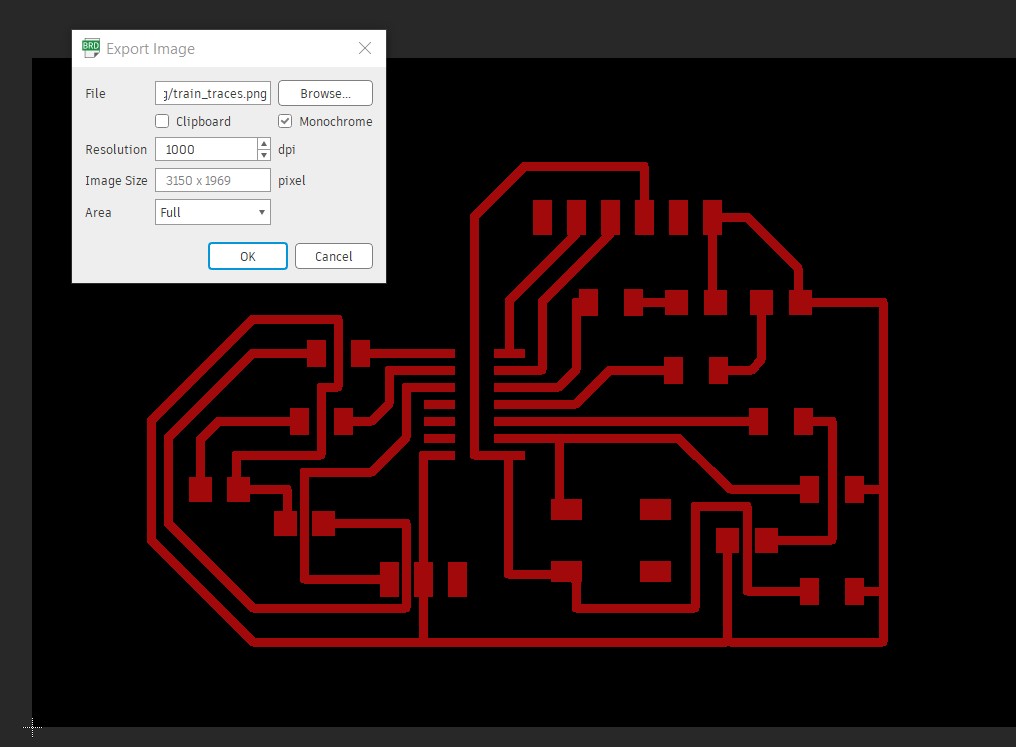
EXPORTING PNG
For the traces: turn all the layers off and leave only the traces layer on. Go to file,
export, image. In the properties box mark monochrome and at least 1000dpi, in browse select were
you want to save this file. For the border: same process as the traces, just leave the border layer on.
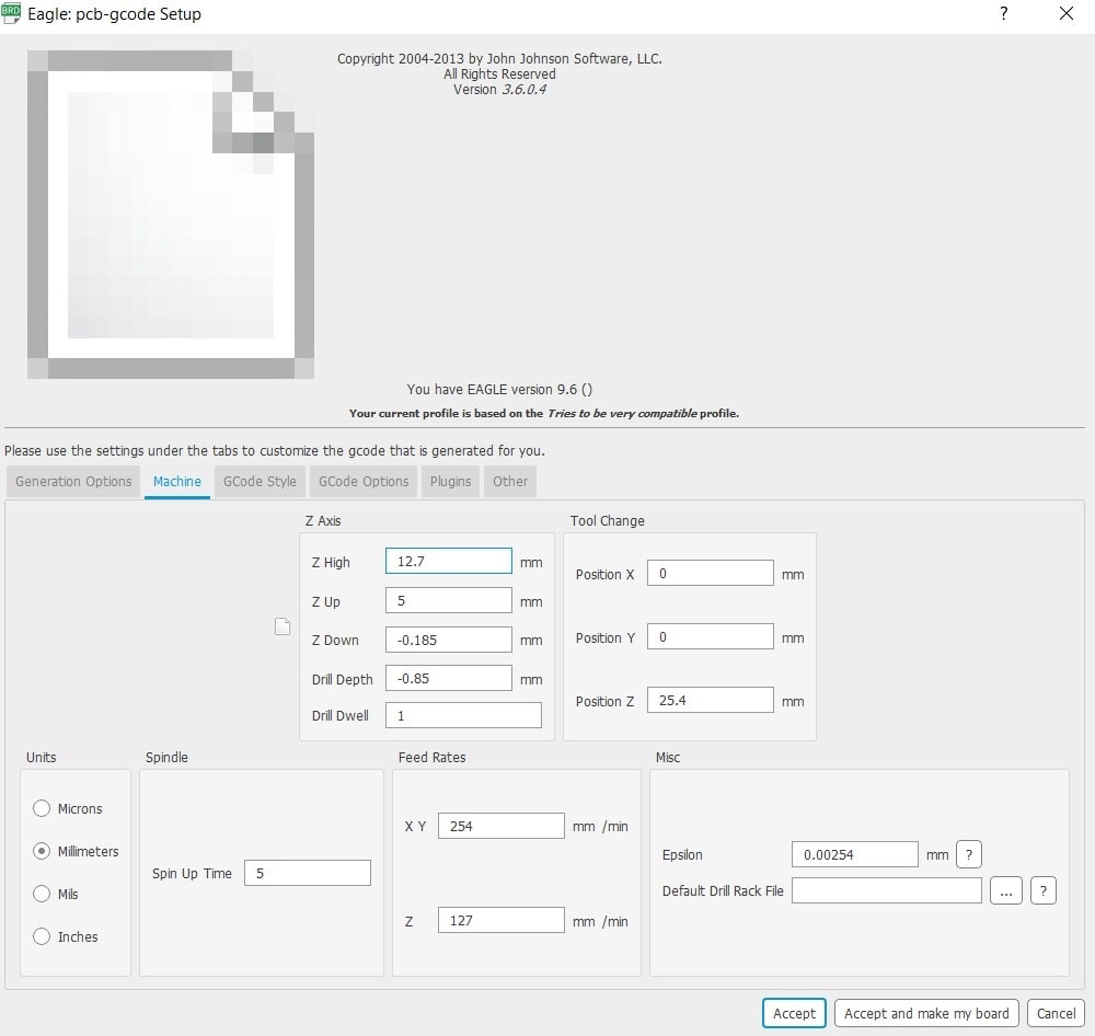
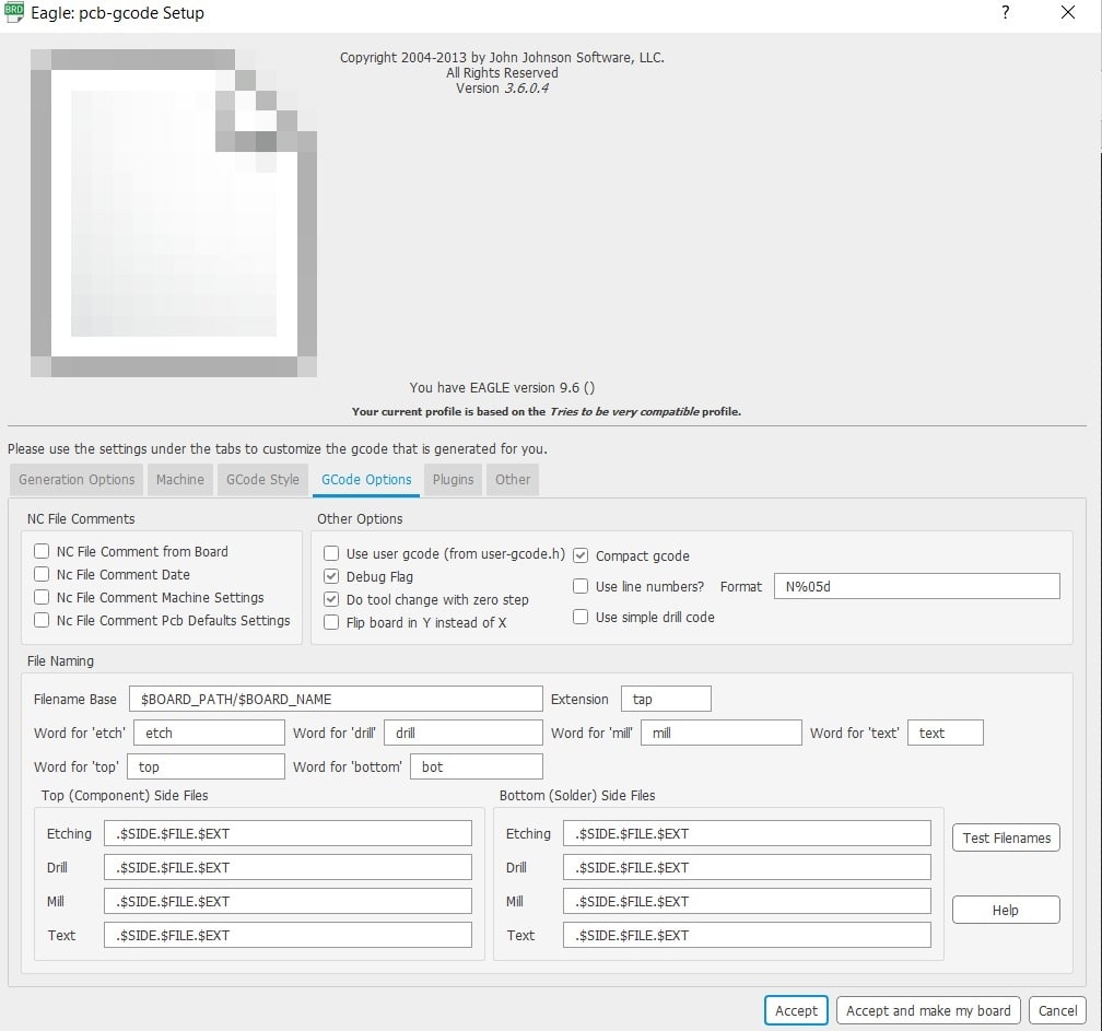
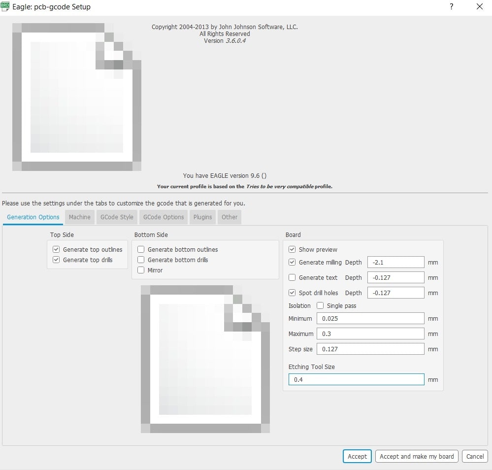
MILLING FILE FROM EAGLE
Eagle has the tools to generate its own file for the milling machine. First you have to dowload the UPL
avaliable
on this
and install it on the computer. Then press ULP and the next window will come out, fill the parameters using the
following parameteres:
You will get a .etch.tap file wich you will later use for milling.
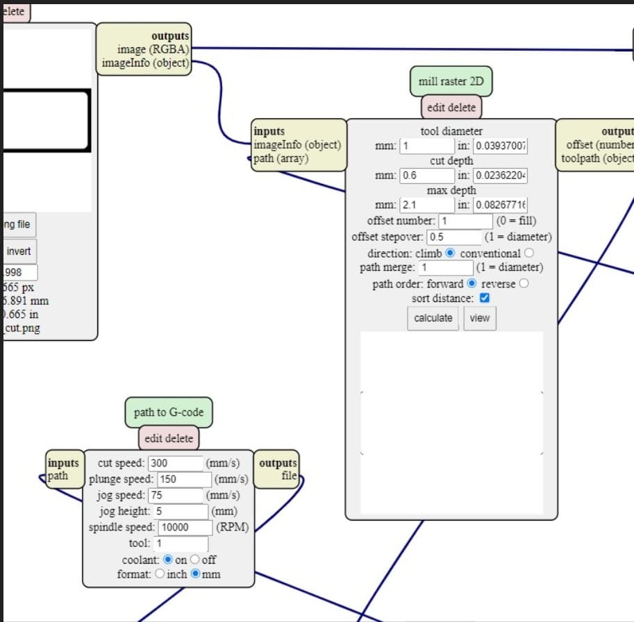
MILLING FILE FROM mods
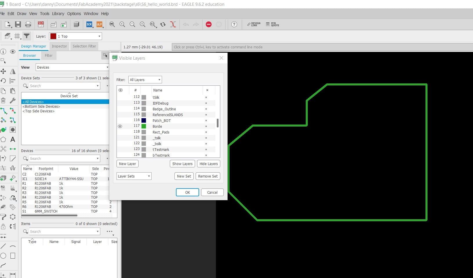
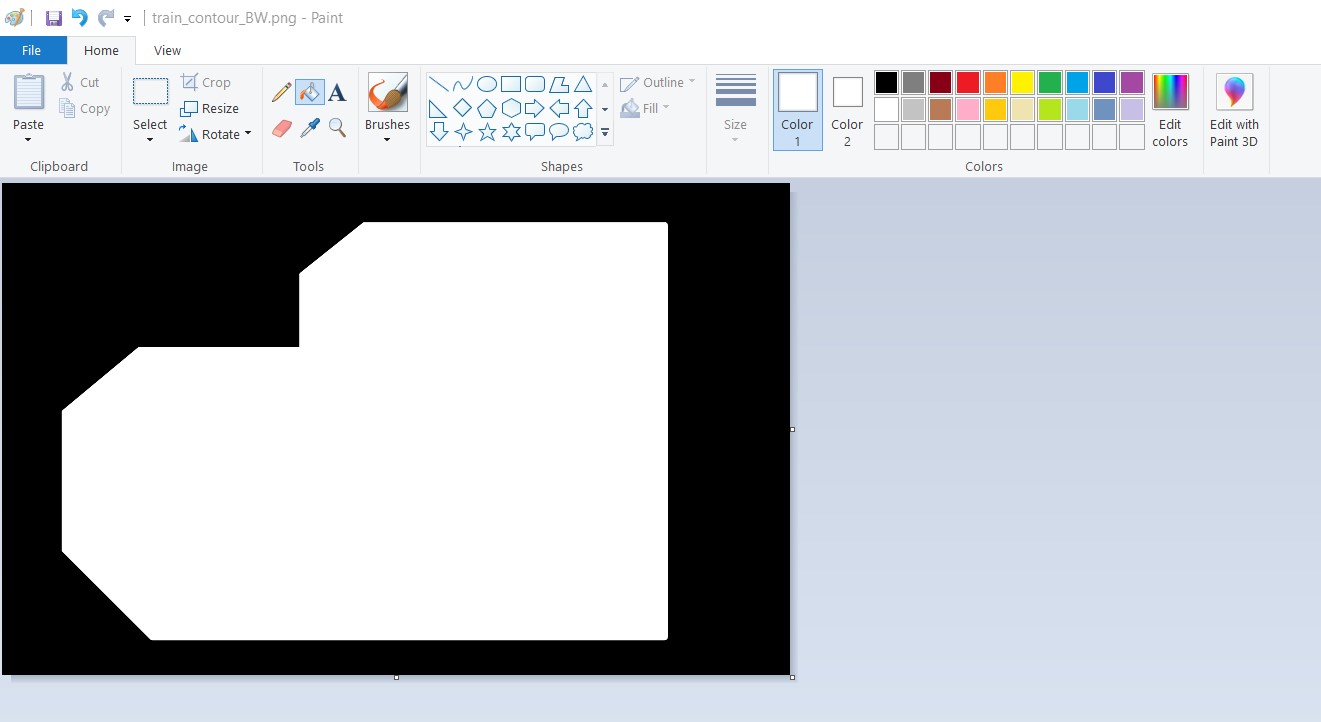
The border is not possible to export on Eagle, so I used mods. It is importat on this point to
edit the png image to fill inside the border, otherwise mods does not recognize it.
It is necesarry to invert the colors in the contour image, for this I use pain, an easy and quick tool to achieve what I need.
The following pictures shows the parameter used on mods:
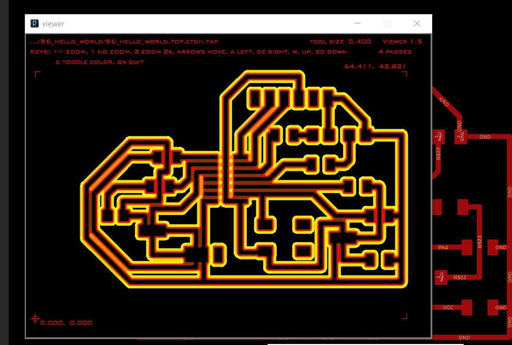
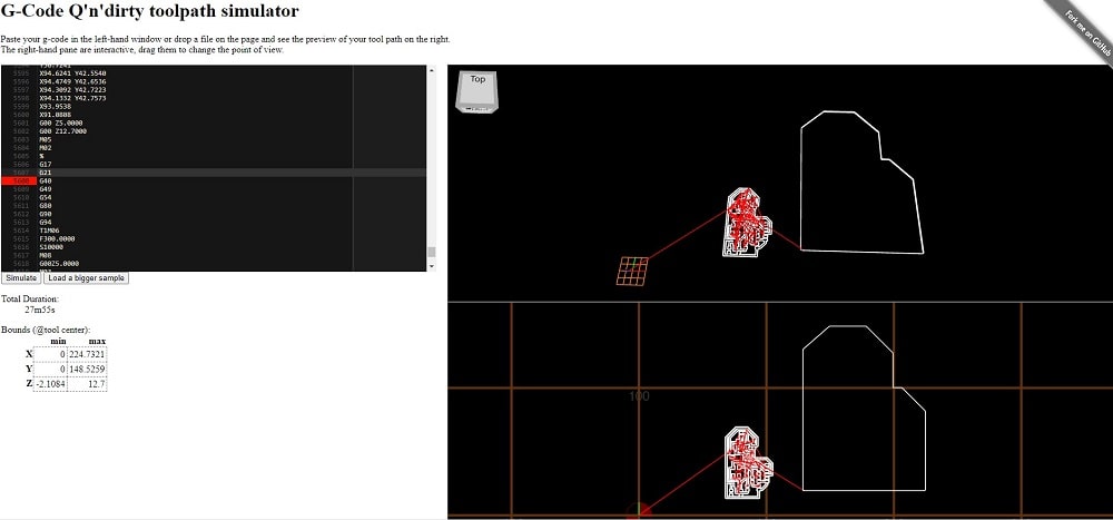
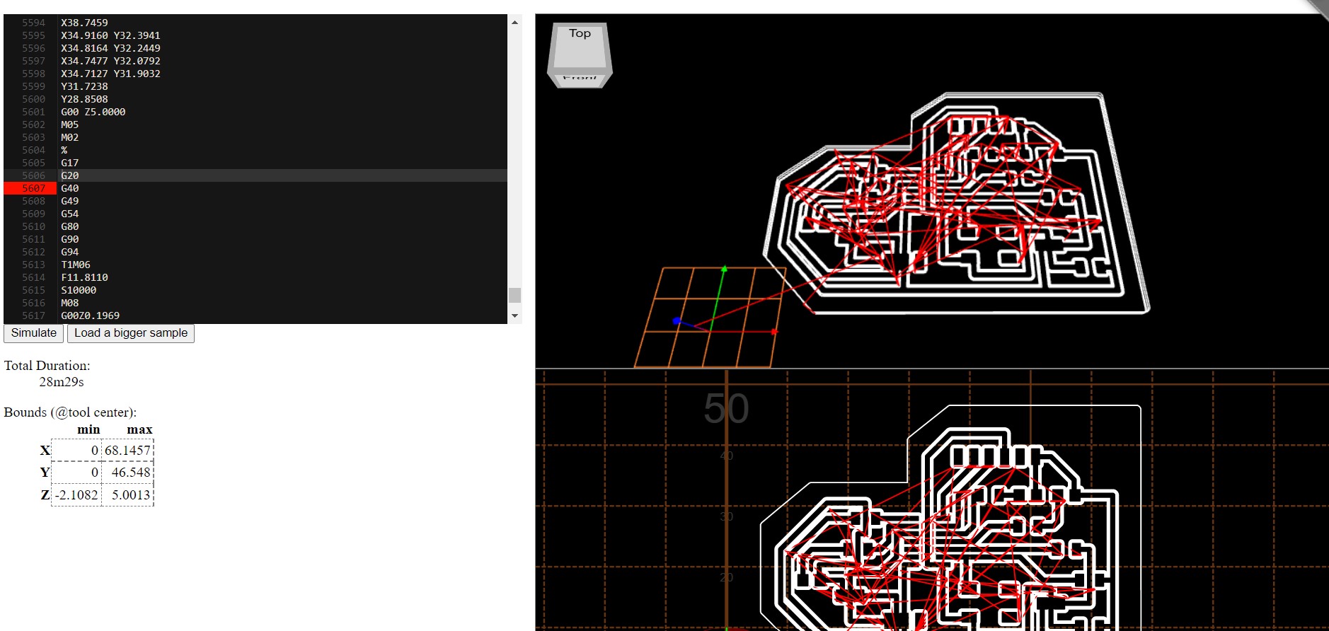
G-CODE SIMULATOR
To make sure the files were right before milling I used the G-code simulator on line and found out
the scale of the border wasn't right.
Fixed it, by generating the files again, something was wrong when I changed the color of the contour using paint, but once I re-did this step itworked. Ready to go!
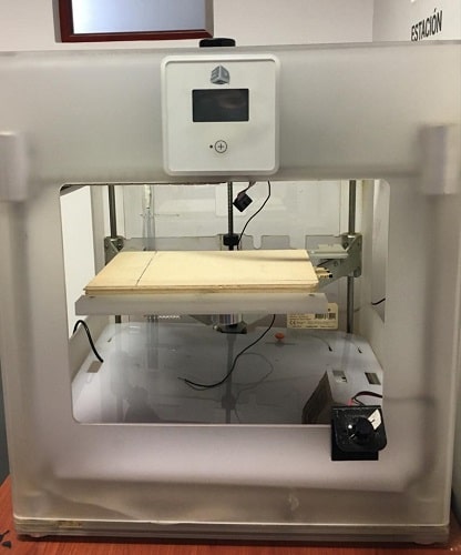
The machine used for this is one fabricated at the lab and hacked there.
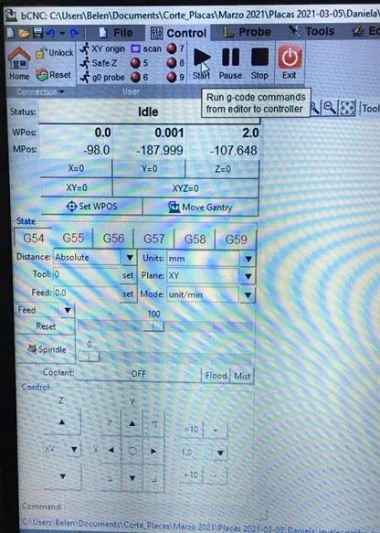
WORKFLOW
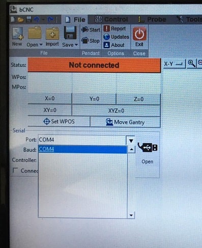
The software used for millin is bCNC.
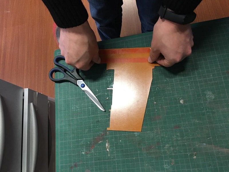
Prepare the cooper plate with a metalc fiber
Add doble faced tape and paste it on the milling wood board
Make sure to paste the plate respecting the x and y axes marked on the milling board
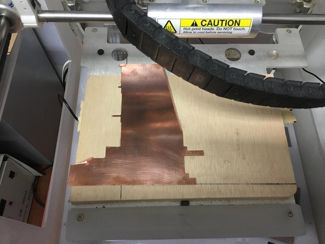
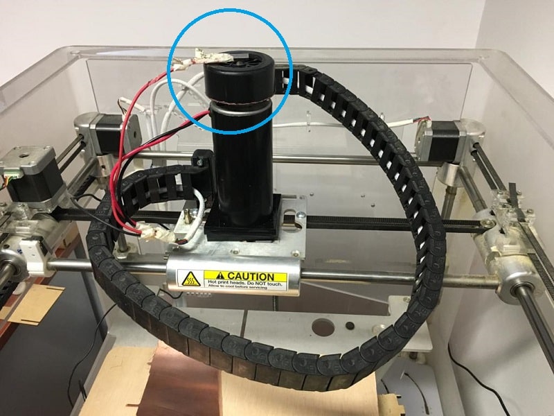
Place the sensor on the copper plate and the magnet on top
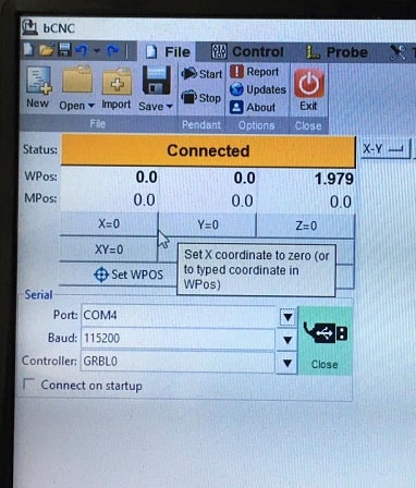
File> serial> Band> COM4> Open
Connect the machine to the computer usb
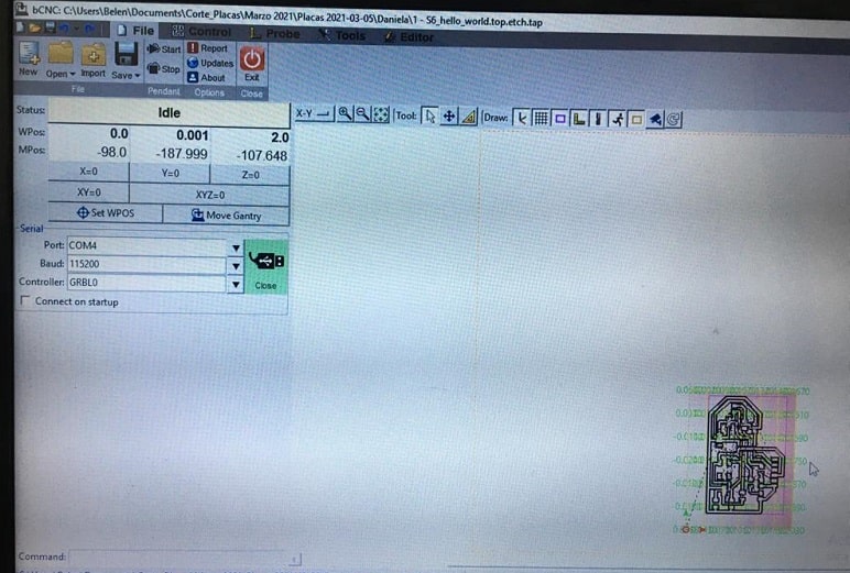
Open file
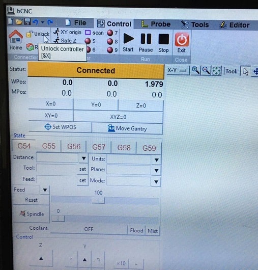
CONTROL: unlock controler
Set x, y and z axes on the milling machine using the arrows and when you are ready press x=0 y=0 z=0
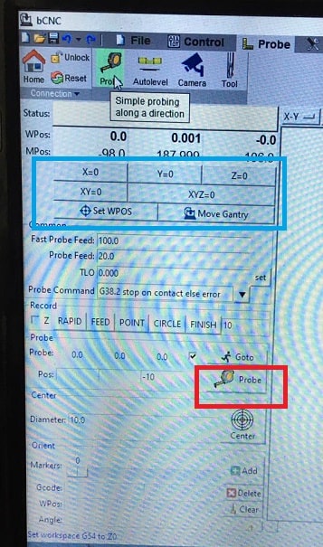
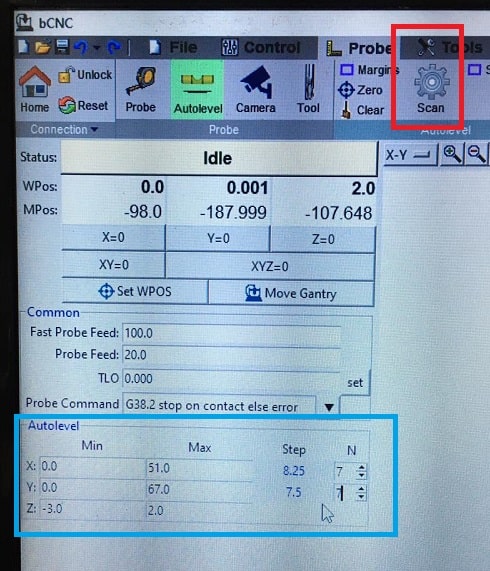
PROBE
AUTOLEVEL: you can copy the parameter on min and max from the gcode simulator
Steps: 7 and 7 for this exercise. This means there will be 49points (7x) where the end mill makes contact.
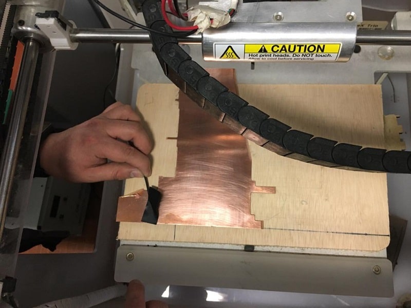
Scan and after a couple of minutes when the scan is done, press probe
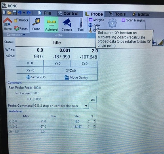
File: save the .probe
Press zero to set the origin
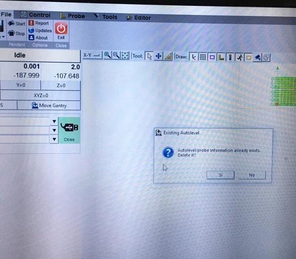
Load .probe file and traces file
A mesage about an existing .probe file will come out: replace it!
Disconect the magnet on top
Turn on the spinner
CONTROL: start
For the border: load file
Press start. In case you need to stop you can press pause or stop in the control pannel
Some Thought about the milling
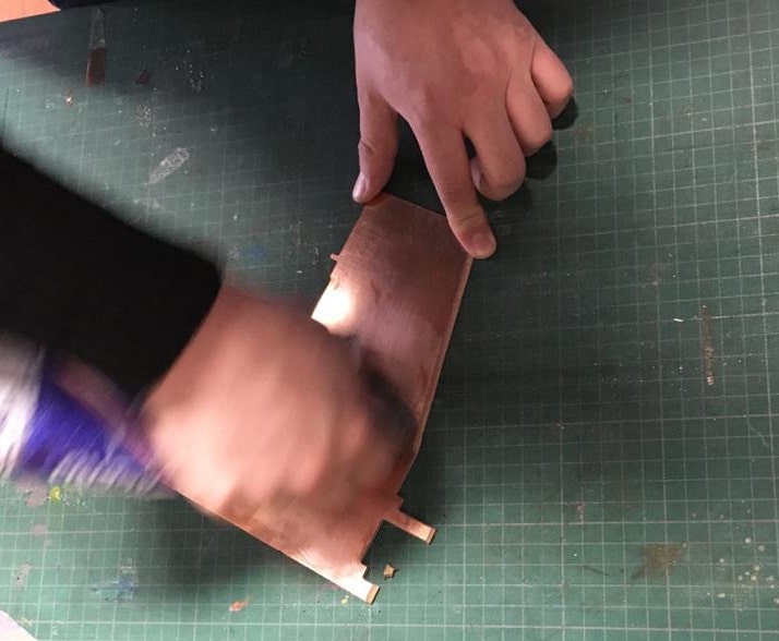
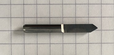
The mill used to engrave and cut the board was the same, a triangular 3mm mill.
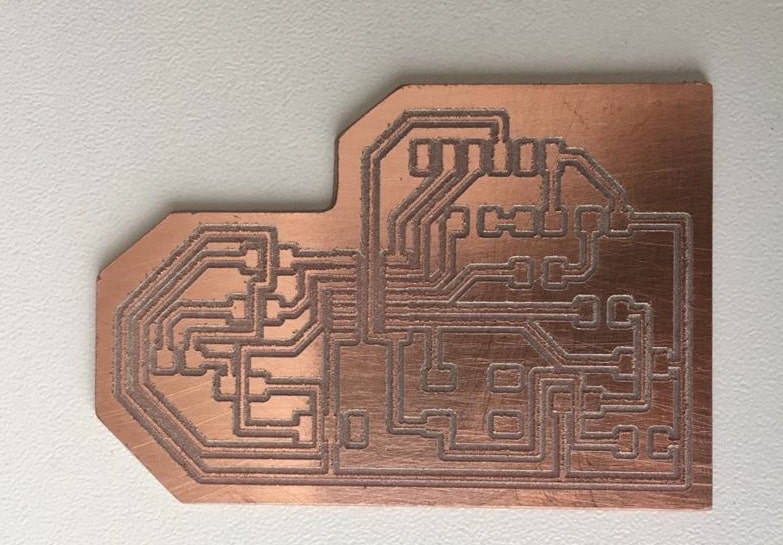
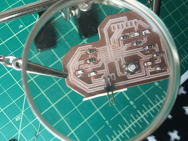
The final result of my board. The edges are not very clean, this is because the mill is not sharp enough.
This can cause conductivity failures later, so it is necessary to sand it or pass a metal mesh to clean these threads. It is important to ensure that the contours of the tracks are free of any copper residue.
COMPONENTS AND SOLDERING
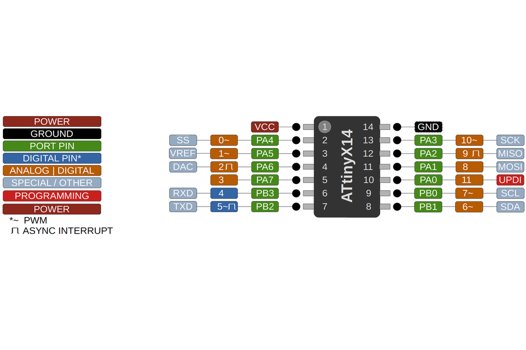
Something important I learned this week is that the micros have predetermined pins and functions.
In this case the pint out for the Attiny1614 is the following and it gave me a further understanding of this
component. Also my classmates recommended me to check the data sheet in case I have more doubths.
For further information about this micro you can visit this site where you will find the Attiny1614 data sheet
Most of the components were avaliable at the lab, still have to figure out what to do with the attiny 1614.
After searching at a couple of local vendors, finally found the Attiny1614. This is the final result of my board
According to the web site there are two ways to install the megaTinyCore on the Arduino IDE:
Installation via the Arduino Board Manager
Manual Installation
I chose the first option, and followed these steps:
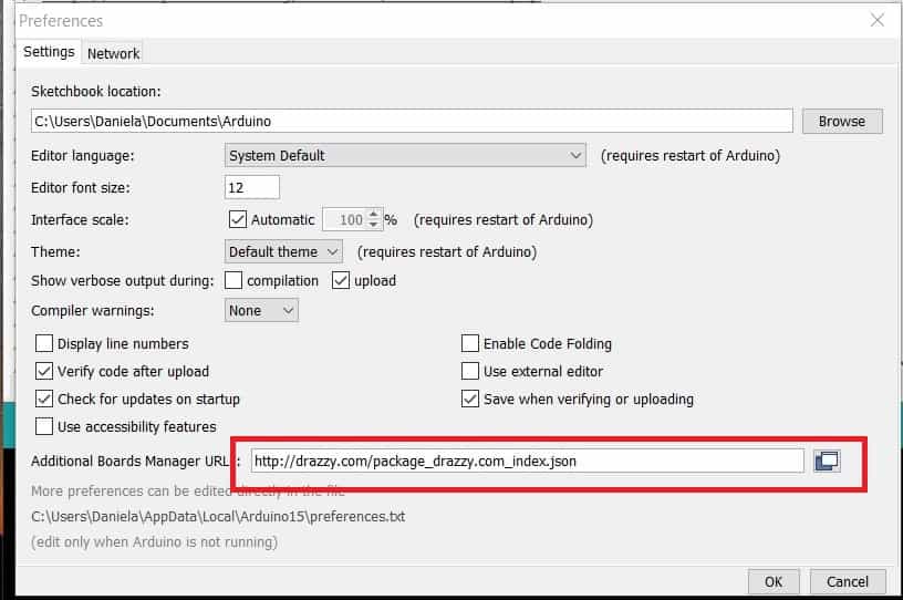
Open the preferences window from the Arduino IDE. Go to File > Preferences or Arduino > Preferences
On the preferences window, locate the “Additional Board Manager URLs” text box and enter http://drazzy.com/package_drazzy.com_index.json into the field as shown below and click the OK button
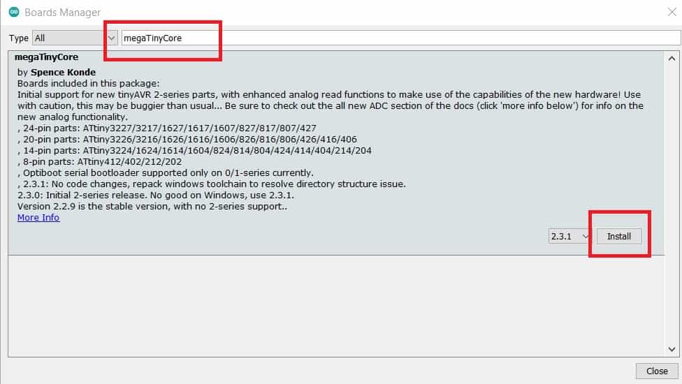
Open the Arduino board manager. Go to tools>Boards>Boards manager
When the board manager opens up, enter megaTinyCore into the search bar and scroll, you will see “megaTinyCore by Spence Konde”, click on install as shown below.
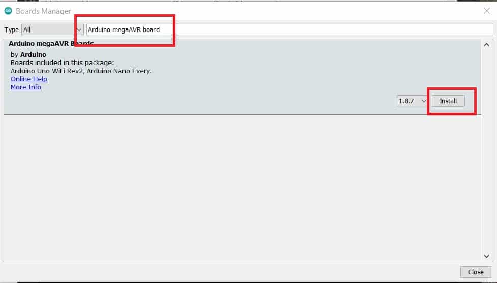
Also, search for the “Official Arduino megaAVR boards” package by Arduino and install the most recent version of that too
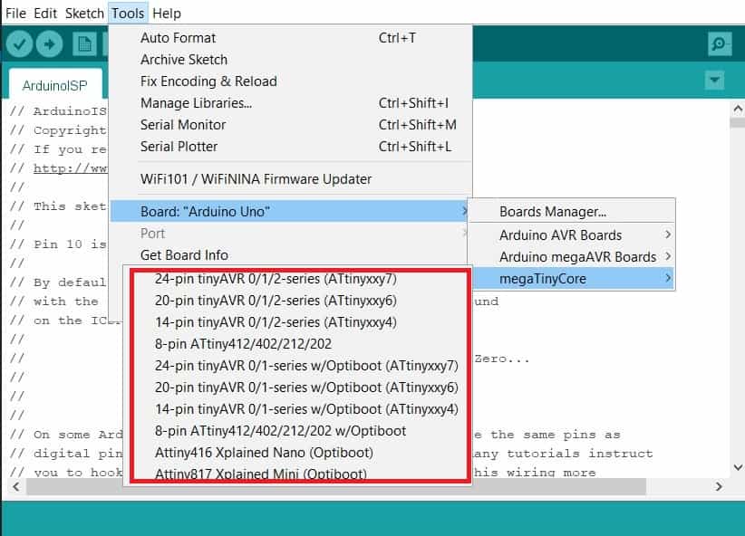
Now the Attiny boards are avaliable under the Boards section Tools>Boards of the Arduino IDE, this means the board installation was successful.
MAKE THE UPDI PROGRAMMER
In order to upload a code to the attiny, is needed to make a UPDI programmer and for this I am going to use an Arduino board and arduino IDE.
First, I have to transform the Arduino board to work as a UPD programmer. Then, I have to connect the attiny to the programmer to upload the code.
1. Transform the arduino to a UPDI programmer
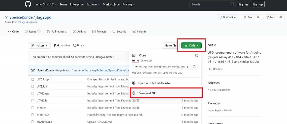
For this is necessary to use the UPDI Arduino sketch created by
ElTangas
The sketch converts ATmega328(p)-based Arduino’s, like the Arduino UNO, Nano, and Pro mini, into a UPDI programmer.
These are the steps to make the UPDI programmer:
Close all instances of the Arduino IDE to avoid errors.
Open the jtag2updi folder after extracting the download
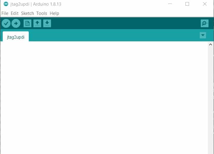
Open the sketch jtag2updi.ino and upload it to the Arduino board you will like to use which for this case is an Arduino UNO.
When you open the code, the .ino file will appear empty and that is fine as all the code is contained in the other files in the same folder as the .ino, but the empty .ino is needed so they can be compiled by the IDE.
With the upload successful, now the UPDI programmer is ready to use.
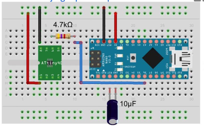
2. Connecting th Attiny and uploading
Connect the ATiny to the Arduino as shown in the schematics below;
To prevent mistakes the following chart shows the pin to pin connection between the Arduino and the Attiny:
Arduino
Attiny
GND
GND
5V
VCC
D6
UPDI
Also add:
4.7Ω resistance
10uf capacitor
3.Upload the code
Follow the next steps:
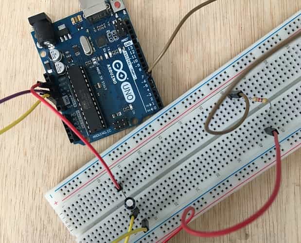
Connect the board to the Arduino
Paste the code. For this a used Adrian's example, avaliable here:
//Adrián Torres - Fab Academy 2020 - Fab Lab León
//tiny1614 hello_train
//
//Original code:Neil Gershenfeld 12/8/19
// This work may be reproduced, modified, distributed,
// performed, and displayed for any purpose, but must
// acknowledge this project. Copyright is retained and
// must be preserved. The work is provided as is; no
// warranty is provided, and users accept all liability.
//
const int ledPin1 = 3;//first light
const int ledPin2 = 6;//white light
const int ledPin3 = 7;//white light
const int ledPin4 = 1;//red light
const int ledPin5 = 2;//red light
const int buttonPin = 0;// button pin
int buttonState = 0;//initial state of the button
int i = 0; //variable intensity led

void setup() { //declaration of inputs and outputs
pinMode(ledPin1, OUTPUT);
pinMode(ledPin2, OUTPUT);
pinMode(ledPin3, OUTPUT);
pinMode(ledPin4, OUTPUT);
pinMode(ledPin5, OUTPUT);
pinMode(buttonPin, INPUT);
}
void loop() {
buttonState = digitalRead(buttonPin);// we read the state of the button
if (buttonState == HIGH) { //if we press the button
digitalWrite(ledPin2, HIGH);
digitalWrite(ledPin3, HIGH);
delay(2000);
digitalWrite(ledPin4, HIGH);
digitalWrite(ledPin5, HIGH);
delay(2000);
digitalWrite(ledPin1, HIGH);
delay(5000);

}
else {  //if we don't press the button
digitalWrite(ledPin1, LOW);
digitalWrite(ledPin2, LOW);
digitalWrite(ledPin3, LOW);
digitalWrite(ledPin4, LOW);
digitalWrite(ledPin5, LOW);
}
}
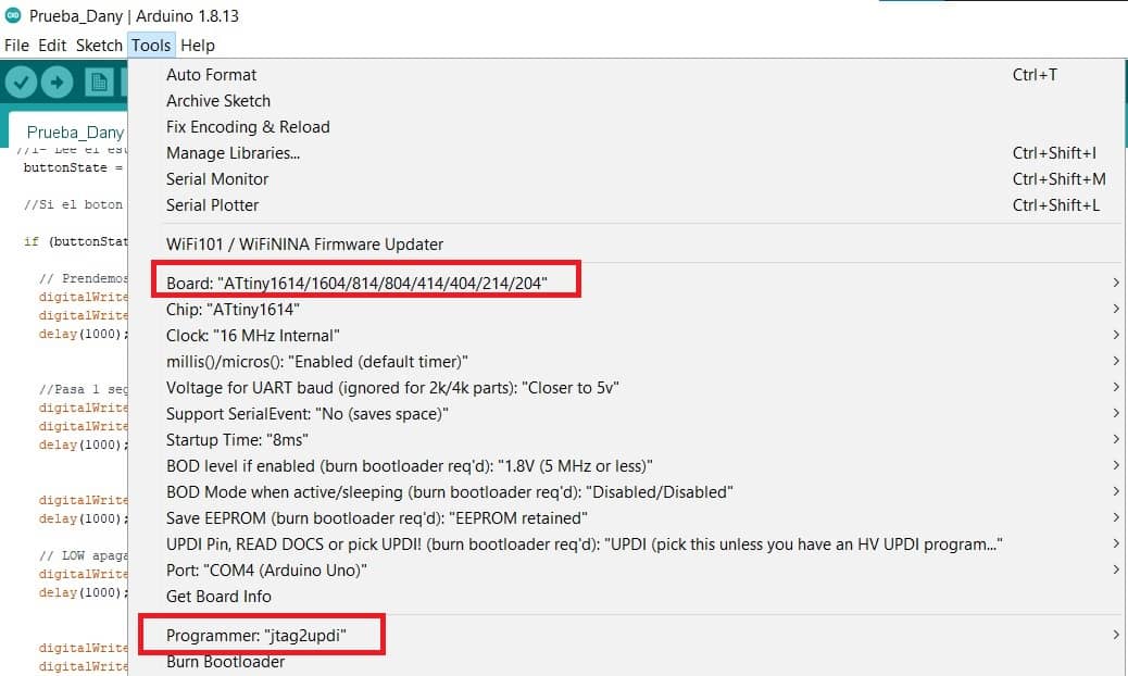
To verify that there is no error, you can go to Tools>Board>and scroll down to see the ATtiny you are working with
on the list and select it.In this case the ATtiny1614
Tell the Arduino to use our programmer. Go to Tools>Programmers>jtag2updi
Click on upload on the IDE and the board should work as programmed.
Based on Adrian's work I made some changes on the code, this is the result:
//Daniela Felix - Fab Academy 2021 - Fab Lab ZOI
//tiny1614
//
//Original code:Neil Gershenfeld 12/8/19
// This work may be reproduced, modified, distributed,
// performed, and displayed for any purpose, but must
// acknowledge this project. Copyright is retained and
// must be preserved. The work is provided as is; no
// warranty is provided, and users accept all liability.
//
const int ledPin1 = 3;//blue led
const int ledPin2 = 6;//red led
const int ledPin3 = 7;//red led
const int ledPin4 = 1;//blue led
const int ledPin5 = 2;//blue led
const int buttonPin = 0;// reset button
int buttonState = 0;//initial state of the button
int i = 0; //variable intensity led

void setup() { //declaration of inputs and outputs
pinMode(ledPin1, OUTPUT);
pinMode(ledPin2, OUTPUT);
pinMode(ledPin3, OUTPUT);
pinMode(ledPin4, OUTPUT);
pinMode(ledPin5, OUTPUT);
pinMode(buttonPin, INPUT);
}
void loop() {
buttonState = digitalRead(buttonPin);// we read the state of the button
if (buttonState == HIGH) { //if we press the button
digitalWrite(ledPin2, HIGH);
digitalWrite(ledPin3, HIGH);
delay(1000);
digitalWrite(ledPin4, HIGH);
digitalWrite(ledPin5, HIGH);
delay(1000);
digitalWrite(ledPin1, HIGH);
delay(1000);
digitalWrite(ledPin1, LOW);
delay(1000);
digitalWrite(ledPin4, LOW);
digitalWrite(ledPin5, LOW);
delay(1000);
digitalWrite(ledPin2, LOW);
digitalWrite(ledPin3, LOW);
delay(1000);

}
else {  //if we don't press the button
digitalWrite(ledPin1, LOW);
digitalWrite(ledPin2, LOW);
digitalWrite(ledPin3, LOW);
digitalWrite(ledPin4, LOW);
digitalWrite(ledPin5, LOW);
}
}
SOME THOUGHTS ABOUT THIS WEEK
This was the hardest week for me so far, lots of information, kind of frustrating at times,
because there are many things I completely don't understand. But I'm going to follow Neil's advice,
(this is something he said during class) "Don't look at this as a linear learning, better to go in spiral,
learn something and come back to it later". That's what I'm gonna do, try to do my best every week, I know
it's gonna take a bigger effort on this tasks, but i'll get it little by little.
Fortunately my classmates and tutor have been patient explainig to me even te most basic stuff and open to
share their knowledge and experience with me.
