prefab
Basics and essentials; starting on September 2020.
What I needed to know before hand to save some time.
SOME WARM UP EXCERCISES ON THE NEXT TOPICS
- Principles and practices
- CAD
- Electronics production
Basics and essentials; starting on September 2020.
What I needed to know before hand to save some time.
- Principles and practices
- CAD
- Electronics production
PRINCIPLES & PRACTICES
"Not so basic when you havent't done this before."
To start, I had to create some accounts that will be useful throughout the process.
Git is a free and open source distributed version control system designed to handle everything from small to very large projects with speed and efficiency. It is designed for coordinatin work among programmers, it can be used to track changes in any set of files.
Link.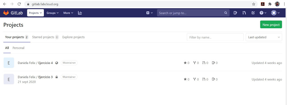
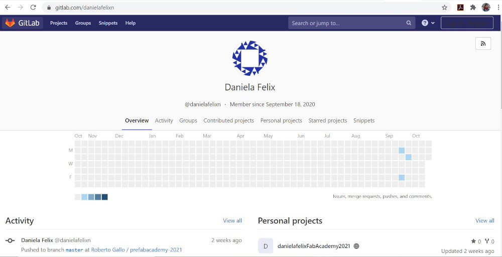
The software infrastructure for projects in the global Fab Lab Network. You can create an account on the Fablabs.io signup page, using the "fablabs" login button to get started with Fabcloud and start contributing.
Link.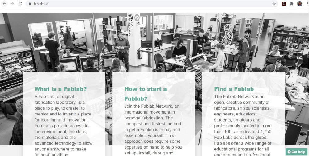
This is a human based design platform mainly for fabbers but we welcome any maker, hacker, DIY and amateur in digital fabrication that wants to create, collaborate and share projects and knoledge.
Link.
Has all the information regarding the Fab Academy, like contents, students, course structure.
Link.
ZOI.ec is the digital complement of the FabLab ZOI laboratory and the local guide to the FabAcademy Program. Here you will find the most relevant content that will help you take the FabAbademy to success. There are several links and information usefull for every assigment.
Link.CAD
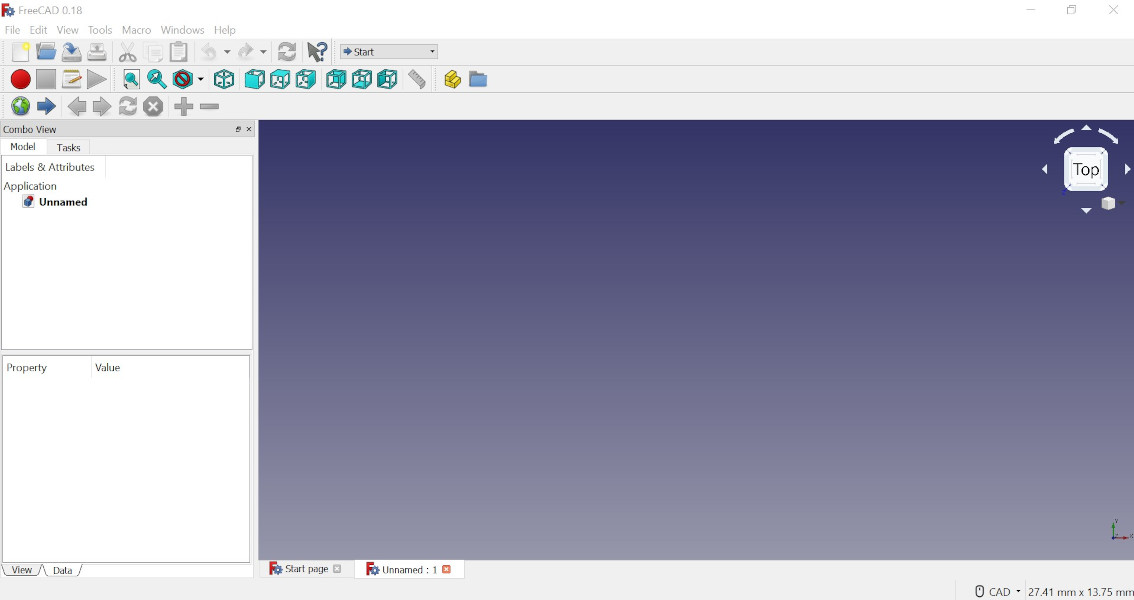
2D and 3D exercise. Tryed to use a new software (FreeCAD).
The suggestion was to try an open source software (similar to Rhinoceros) which will allow me to parametrize my work. I downloaded FreeCAD, followed some tutorials and steps avaliable, but couldn't figure out how it works. (Maybe the interface wasn't intuitive for me).
I preferred to work with Rhinoceros from Autodesk as my training and practice has been with this software. For the task, a parametric piece had to be elaborated where the necessary tolerances for laser cutting are contemplated.
Drawing this piece in 2D and 3D was easy, the challenge was to parameterize it. For this I used grasshopper which is a plug in available in Rhinoceros. It wasn't easy since I don't have much experience in parameterization. I found some tutorials that were helpful and several options came up to solve this activity.
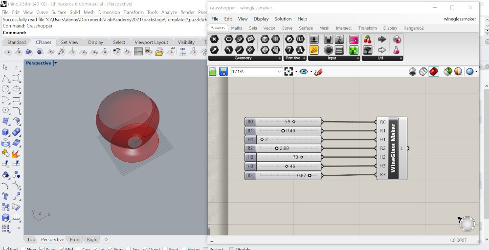 First try, found this algorithm that allows to modify the cup in various parameters.
However, they are not adaptable parameters to new forms, so it did not work
the way I needed it to.
First try, found this algorithm that allows to modify the cup in various parameters.
However, they are not adaptable parameters to new forms, so it did not work
the way I needed it to.
 Second try, the logic was to find the center point of a surface (didn't need it to be in 3D)
and from that point make an offset to define the kerf. For this exercise I
used a 2pt rectangle and a 4pt surface linked to a squared surface. I could
achieve the center point but wasn't enough, I needed at least 4 points located
in different coordinates.
Second try, the logic was to find the center point of a surface (didn't need it to be in 3D)
and from that point make an offset to define the kerf. For this exercise I
used a 2pt rectangle and a 4pt surface linked to a squared surface. I could
achieve the center point but wasn't enough, I needed at least 4 points located
in different coordinates.
Third try, use a curve that could be divided into segments with a slider, then extruded in Z axis, make a linear align to repeat this points. The result wasn't what I was needing.
Forth try, draw a geometry in Rhino, linked it to grasshopper and divide it into segments, use sliders to change the number of segments in U and V axis. Usefull to understand how this piece could change according to my needs. Still, couldn't find out how to set the points where I need to and modify them.
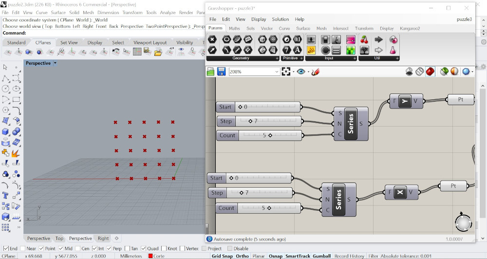
Fifth try, using cross reference I manage to set points in X and Y axis, modify the number of points and the distance between them. It is important to set the move option to shift the points where needed. Helpfull to understand the possibility of movement of the points.


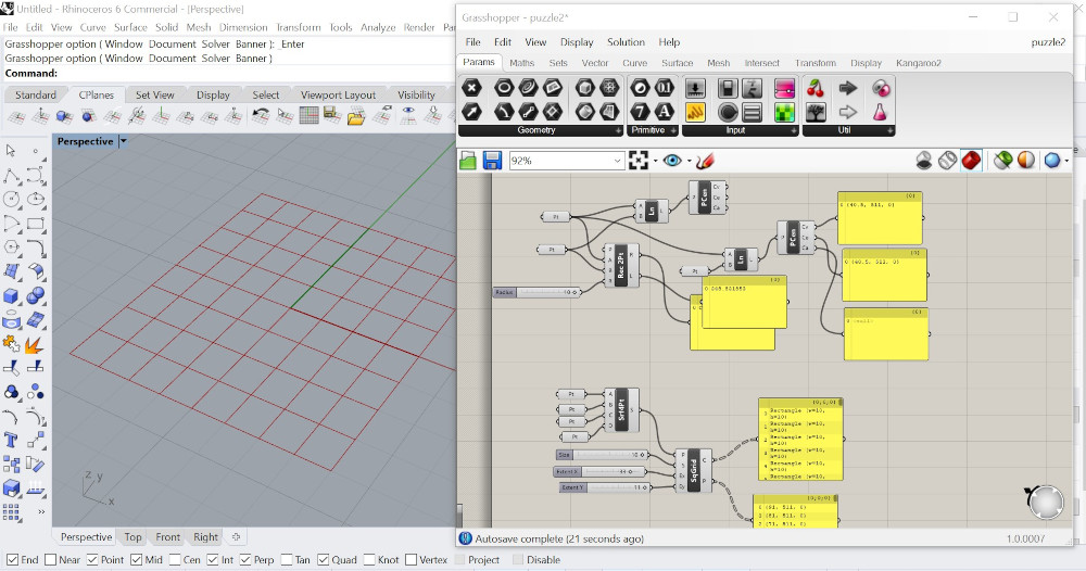
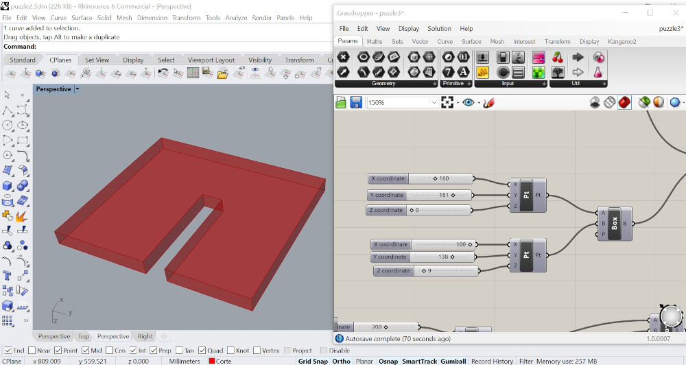
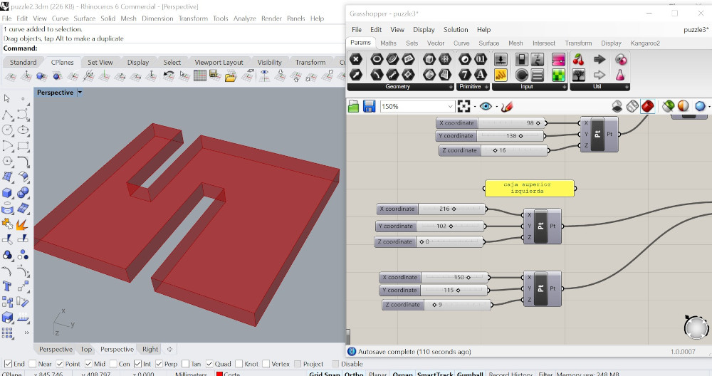
Sixth try, started creating a box, using construct points which could be modified in x, y, z axis, these attached to a slider to contol de dimentions. Then added another box located in the center of the first box to divide it into two parts, also with construct points to control its dimentions. This part was key to achieve my piece, it helped me understand I can substrac one element from another and control it.
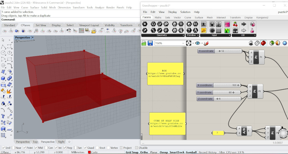

Seventh try, started creating a box, using construct points which could be modified in x, y, z axis, these attached to a slider to contol de dimentions. Then added another box located in the center of the first box to divide it into two parts, also with construct points to control its dimentions. This part was key to achieve my piece, it helped me understand I can substrac one element from another and control it.
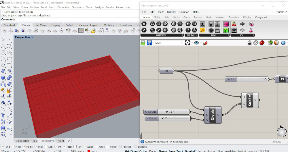
Eighth try, mixed two options, first an isotrim linked to a surface and a divide domain with a slider to create a variation of divisions, then added an extrusion in the Z axis linked to the surface to define its width. This step was also key to modify the width of material I need to use; it was a mix of some of the attempts done before.


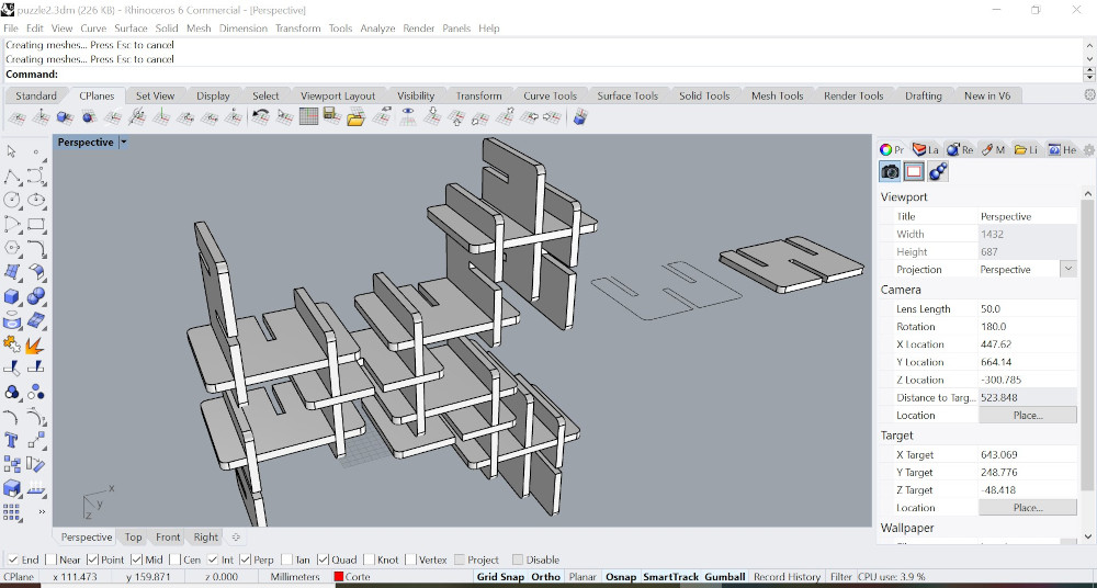
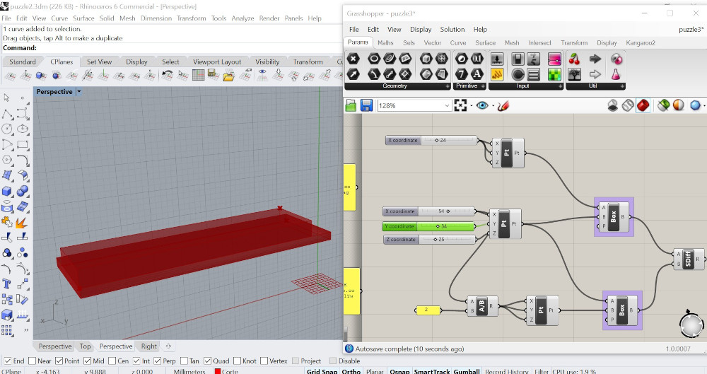
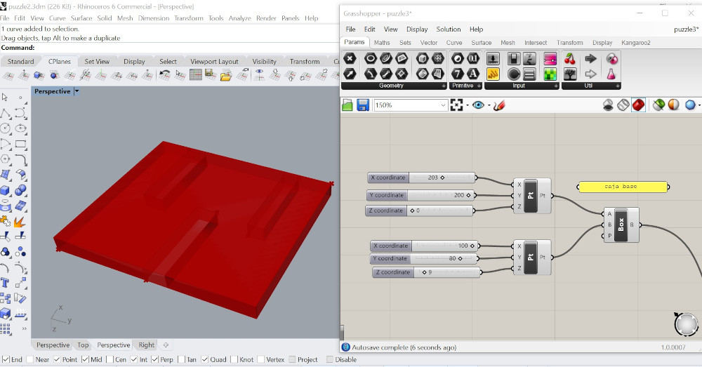
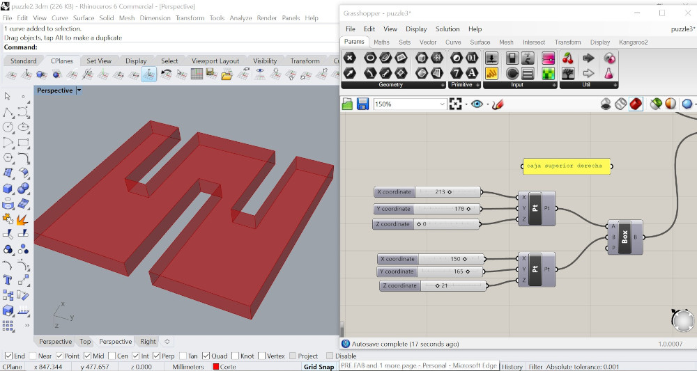
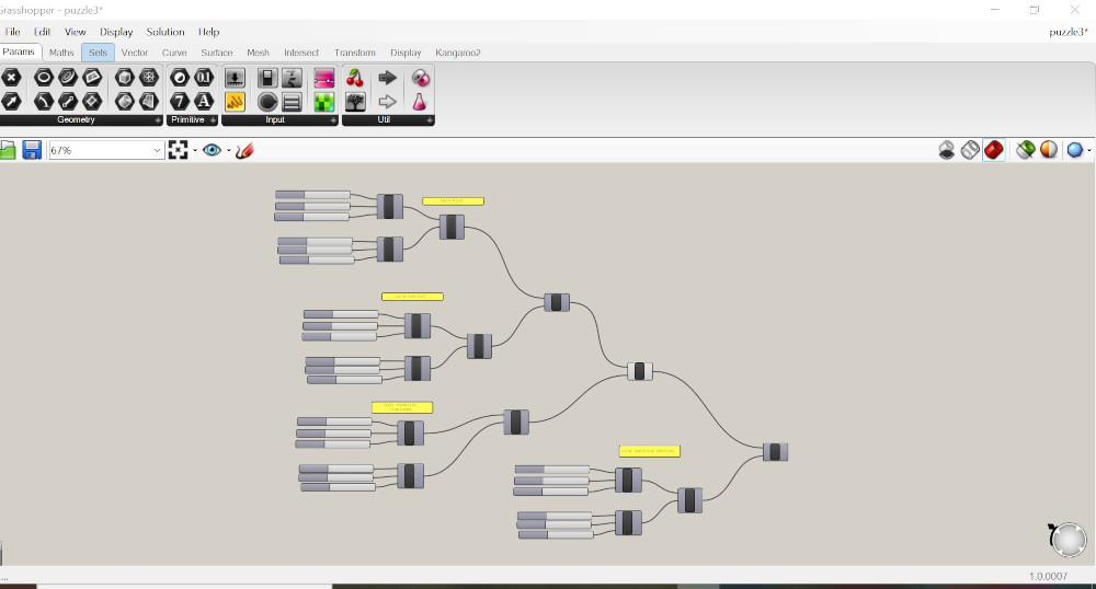
Nineth try, understood that I had to create a box with modifiable parameters where I could control its lenght, width and hight; then add other boxes with the same modifiable parameters and subtract one from the other, repeat this step as many times as needed. Finally made it, I still have to addapt this algorithim to understandable coordinates and real measurements. This exercise will allow me modify the selected piece according to the material avaliable and width.
There are some important concepts to know about:
Parametric design is a process based on algorithmic thinking that enables the expression of parameters and rules that, together, define, encode and clarify the relationship between design intent and design response. Parametric design is a paradigm in design where the relationship between elements is used to manipulate and inform the design of complex geometries and structures. The term parametric originates from mathematics (parametric equation) and refers to the use of certain parameters or variables that can be edited to manipulate or alter the end result of an equation or system. While today the term is used in reference to computational design systems, there are precedents for these modern systems in the works of architects such as Antoni Gaudí, who used analog models to explore design space.
In mathematics and computer science, an algorithm is a finite sequence of well-defined, computer-implementable instructions, typically to solve a class of problems or to perform a computation. Algorithms are always unambiguous and are used as specifications for performing calculations, data processing, automated reasoning, and other tasks.
Grasshopper is a visual programming language and environment that runs within the Rhinoceros 3D computer-aided design (CAD) application. The program was created by David Rutten at Robert McNeel & Associates.Programs are created by dragging components onto a canvas. The outputs to these components are then connected to the inputs of subsequent components. For designers who are exploring new shapes using generative algorithms, Grasshopper® is a graphical algorithm editor tightly integrated with Rhino’s 3-D modeling tools. Unlike RhinoScript, Grasshopper requires no knowledge of programming or scripting, but still allows designers to build form generators from the simple to the awe-inspiring.
Always necesary to remember some stuff
Download Grasshopper here. You can have it with the Rhino 7 with the free trial for 90 days.ELECTRONICS PRODUCTION
I started with TINKERCAD, following some turials avaliable. For some reason we couldn't figure out why this web site didn't work on my computer. It stayed frozen, loading and loadig with no response. I was able to remotely access my office computer and do some exercises.
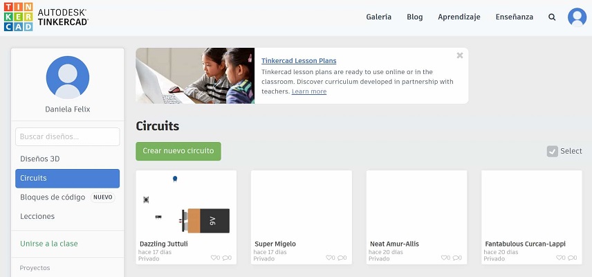
My electronic's knowledge at this point was practically null. I started with the following tutorials to understand the basics: concepts.
Tinkercad Circuits: Introducción a la simulación de circuitos eléctricosy.
Tinkercad - 01: Simulación de Arduino (Encendiendo led's).
Aprendiendo Arduino y Tinkercad - 2 - Semáforo con Arduino).
TinkerCAD Circuits - Ultrasonic Sensor triggers LED.
A simple guide to electronic components.
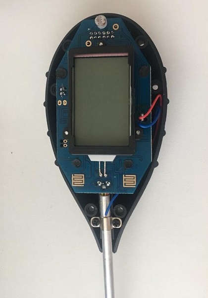
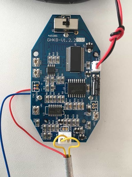
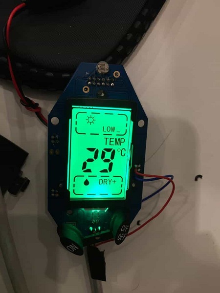
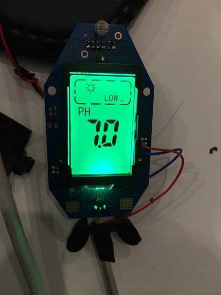
It's always fun to open up some stuff.
As part of my final project , I want to incorporation a couple of sensors, including a humidity sensor for vegetation. I decided to open one that I had at home to see its internal components. At this point I still did not understand the name or operation of each of the pieces, however it helped me to physically identify them.
Some other websites I found usefull to understand the use of each component:
Símbolos eléctricos y electrónicos.
Now, time to apply these basic concepts.
![]() Eagle is a scriptable electronic design automation (EDA) application with schematic
capture, printed circuit board (PCB) layout, auto-router and computer aided manufacturing (CAM)
features. EAGLE stands for easily applicable graphical layout editor. It was acquired
by Autodesk in 2016.
Eagle is a scriptable electronic design automation (EDA) application with schematic
capture, printed circuit board (PCB) layout, auto-router and computer aided manufacturing (CAM)
features. EAGLE stands for easily applicable graphical layout editor. It was acquired
by Autodesk in 2016.
It is avaliable to dowload for free here:
Download EAGLE.
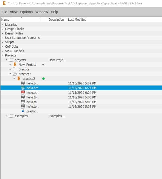
Create a new folder, new project, new schematic
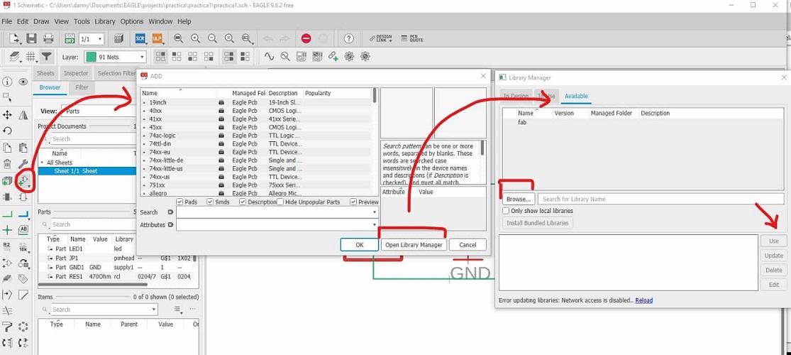
Load the fab library and add the necesary components
Download component libraries.
Here is a preview of the first schematic diagram and board layout exercise:
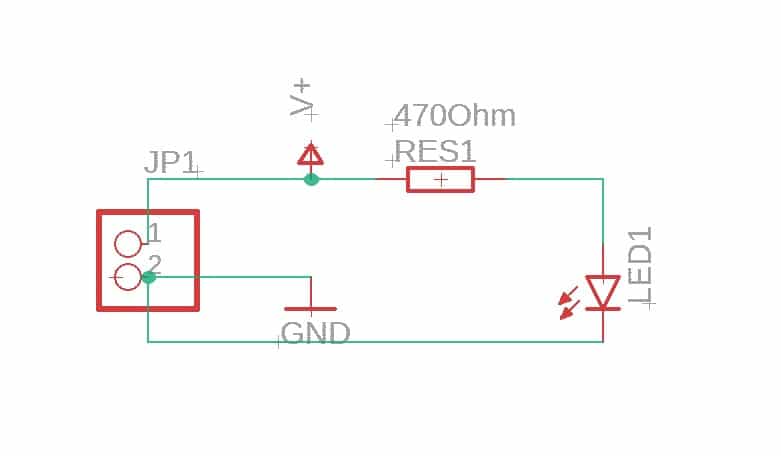
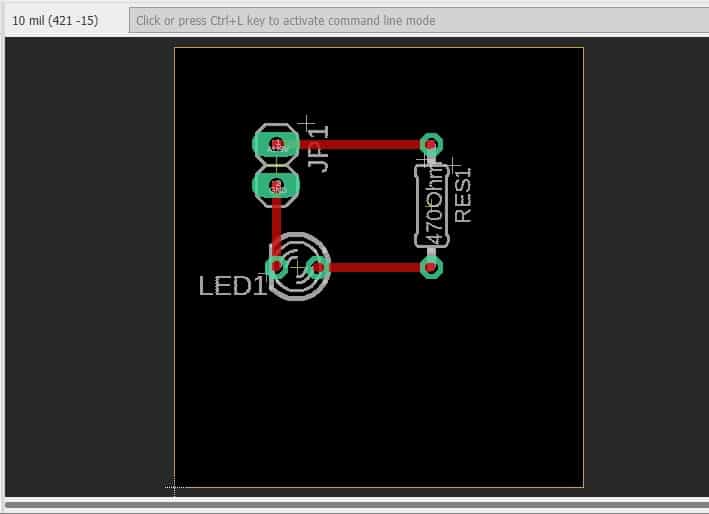
Schematic diagram: in electronics is a drawing representing a circuit. It uses symbols to represent real-world electronic components. Shows the components and interconnections of the circuit using standardized symbolic representations. The presentation of the interconnections between circuit components in the schematic diagram does not necessarily correspond to the physical arrangements in the finished device The most basic symbol is a simple conductor (traces), shown simply as a line. If wires connect in a diagram, they are shown with a dot at the intersection.
Board layout: is the representation of an integrated circuit in terms of planar geometric shapes which correspond to the patterns of metal, oxide, or semiconductor layers that make up the components of the integrated circuit.
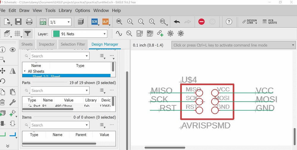
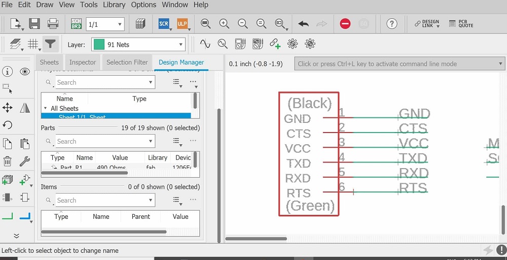
Second exercise. Arduino
SCHEMATIC:
Add components:
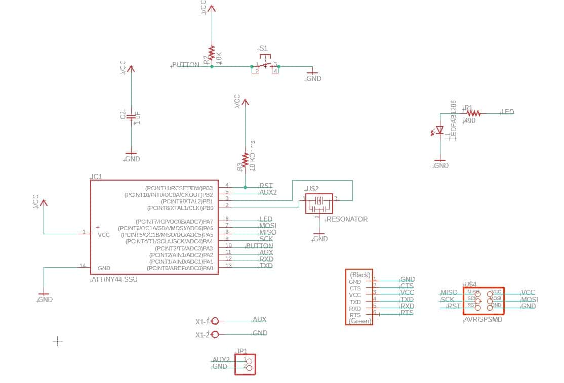
Connect components with wires (see images below)
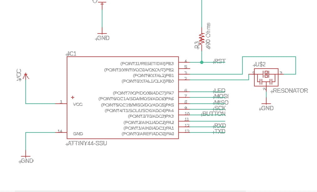
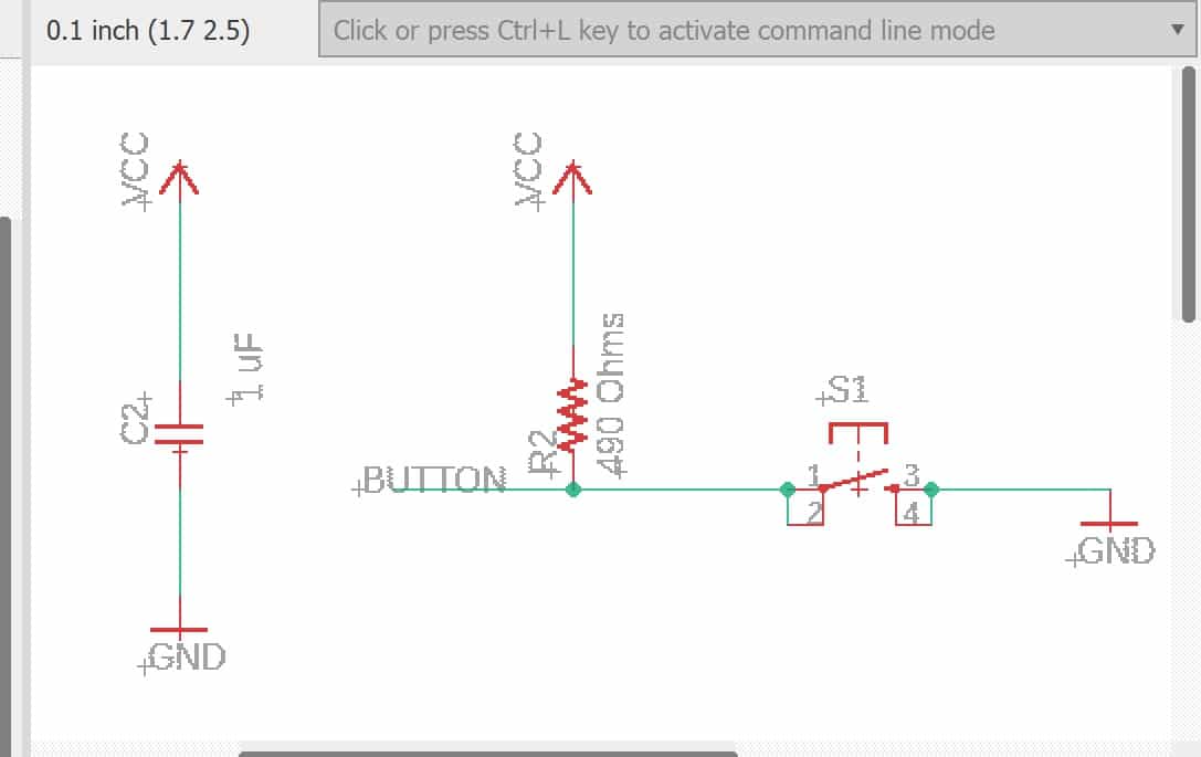
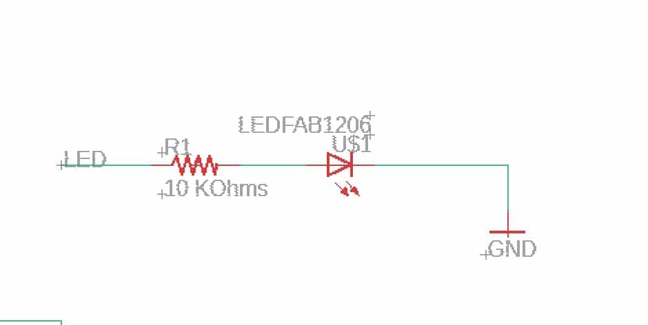

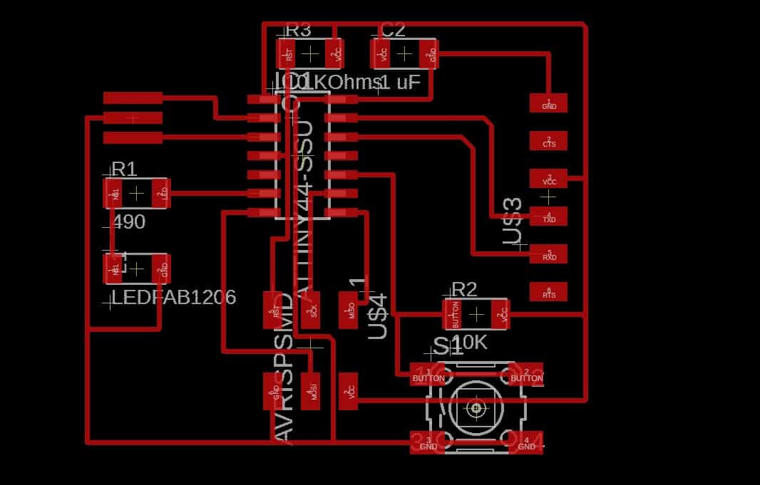
Final result:
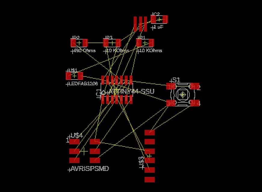
BOARD:
Set the components in a clear way. At the begining it could be really confusing:
Check that all wires are connected correctly using the "erros tool"
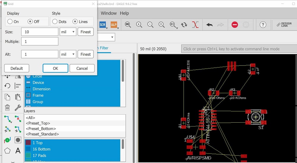
EXPORT THE BOARD DESIGN:
Prepare te board for milling
Do this for the traces and the contour


GENERATE THE G-CODE:
FIRST OPTION: Using mods:
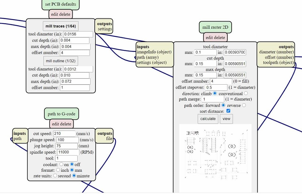
This is the result for traces

Setting for the contour

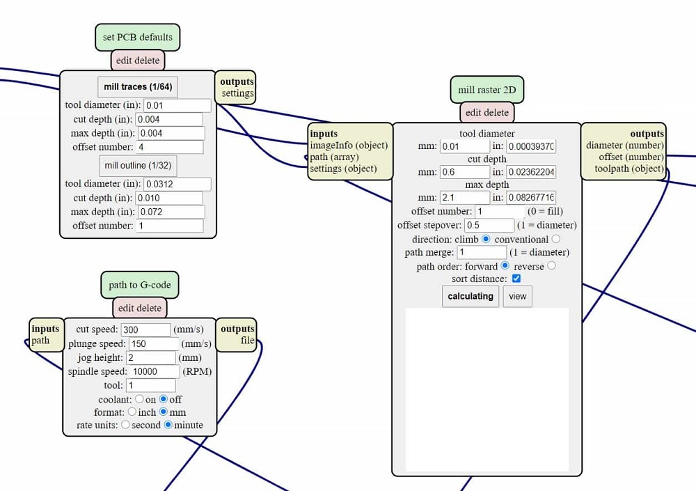
Files here:
Contour.SECOND OPTION: On Eagle:
Find the set up details here:
Fab Lab ZOI.


