To understand the components I found these sites with definitions, it may
seem very basic but it's been usefull.
Símbolos eléctricos y electrónicos.
Definiciones de componentes electrónicos.
BUILDING THE FAB TinyISP
Understanding little by little.
I'm completelly new in this field, so to start I'm just following instructions as told.
This link was really usefull to understand what to do and how to do it
Building the FabTinyISP.
The FabTinyISP is a "low-speed" USB 1.1 device. This is the slowest (and one of
the oldest) of the USB device types. Typically used for mice and keyboards,
low-speed devices operate at 1.5MHz and have much less strict timing requirements,
which enables a purely software-based implementation of the USB protocol to be
used (the ATtiny45 does not have hardware USB capability).
PCB FABRICATION
First, what is a pcb? A printed circuit board (PCB) mechanically supports and electrically connects
electrical or electronic components using conductive tracks, pads and other
features etched from one or more sheet layers of copper laminated onto and/or
between sheet layers of a non-conductive substrate. Components are generally
soldered onto the PCB to both electrically connect and mechanically fasten
them to it.
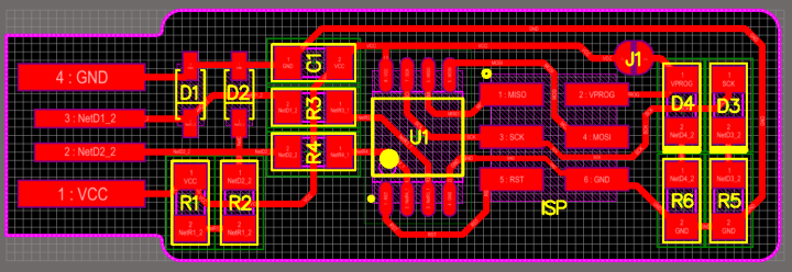
To create the traces and board outline I had to download the files here:
Traces (1000 dpi)
Outline cut (1000 dpi)
I added my initials on the board using illustrator, and exported as png.
You can find the file here:
Illustrator file.
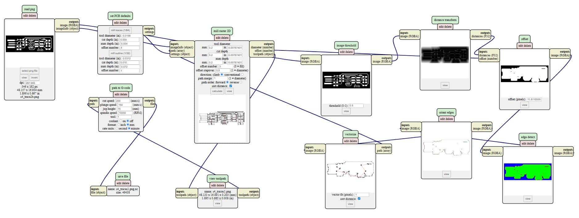
Once we had the file ready we used mods to generate the G/code. On mods follow this steps:
- Access to the software: mods
- Right click, programs
- Open server program
- G-code
- Mill 2D png
In mods, select the png file, set the parameters for the mill raster and
the path for G-code. Once everything is ready press calculate and you'll get
a simulation of the code in an pop up window.
Same steps for the contour, but different parameters:
FILES
Mods files
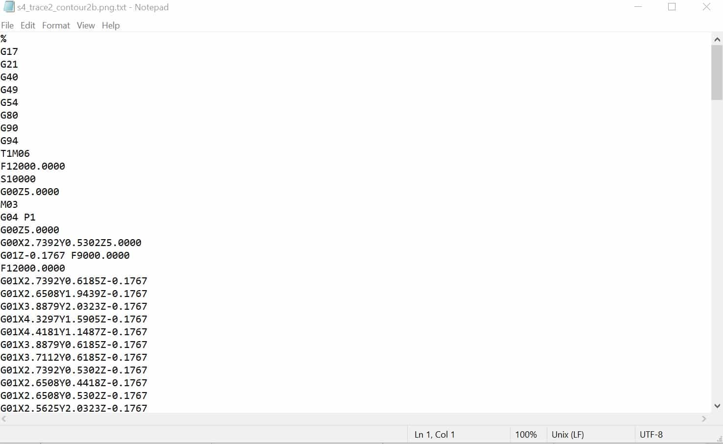
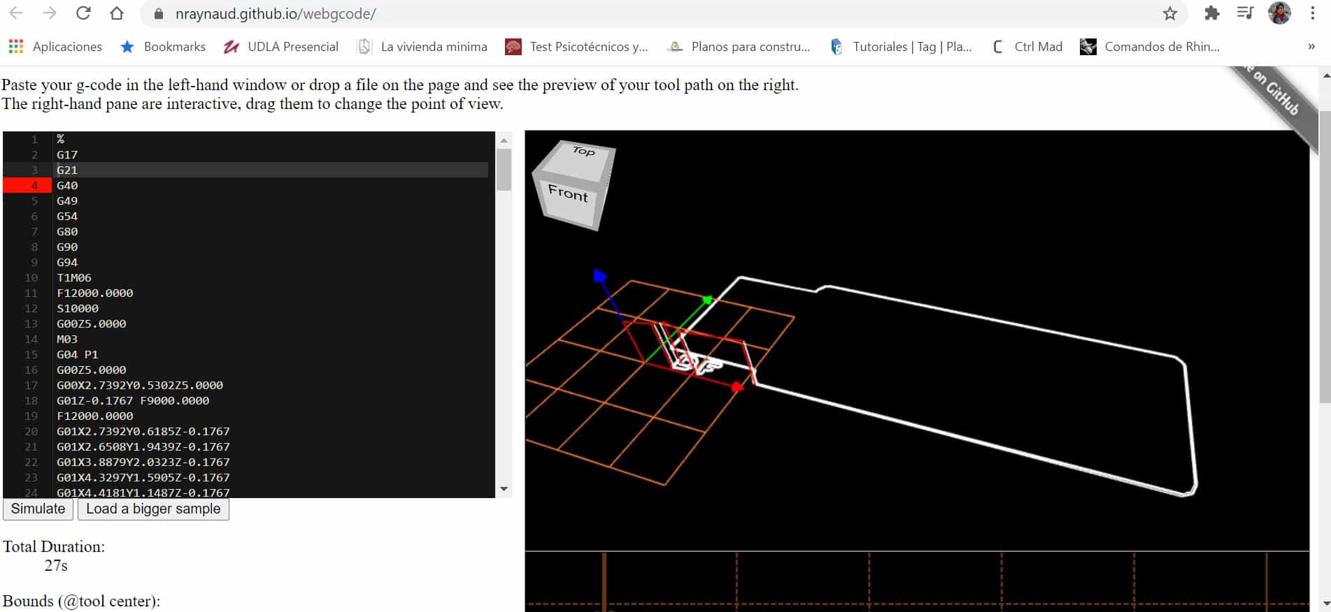
G-CODE SIMULATOR
A G-Code simulator is a type of software tool that provides a virtual representation of a
CNC machine's tool path made by following the instructions in a G-Code file.
They range from simple simulators that output a single image of the tool path to
complex tools that can detect collisions and plot the path in 3D.
To make sure the parameters were right I used a G-Code simmulator, avaliable
on this link:
G-code simmulator
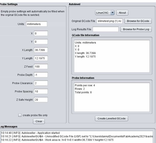
AUTOLEVELER
The auto leveler, leveling instrument, or automatic level is an optical instrument used to
establish or verify points in the same horizontal plane. It is used in surveying and
building with a vertical staff to measure height differences and to transfer, measure
and set heights.
To ensure that the tracing lines are even it was necessary to do an autoleveler.
For this we installed it and load the .nc file with the traces, set the parameters
and generate the autoleveler.
FILES
Autoleveling file for traces
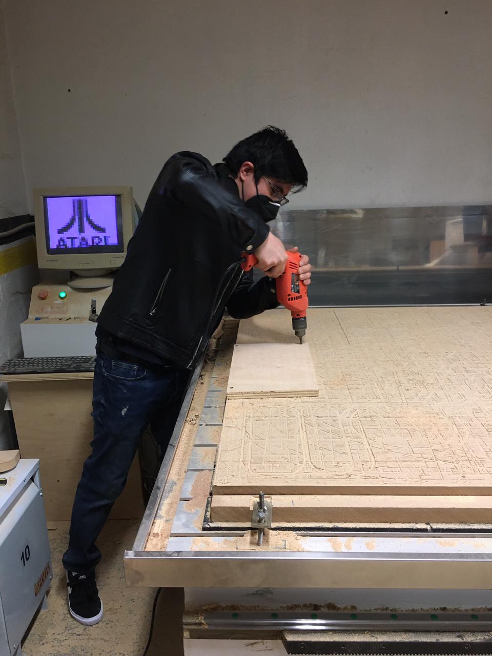
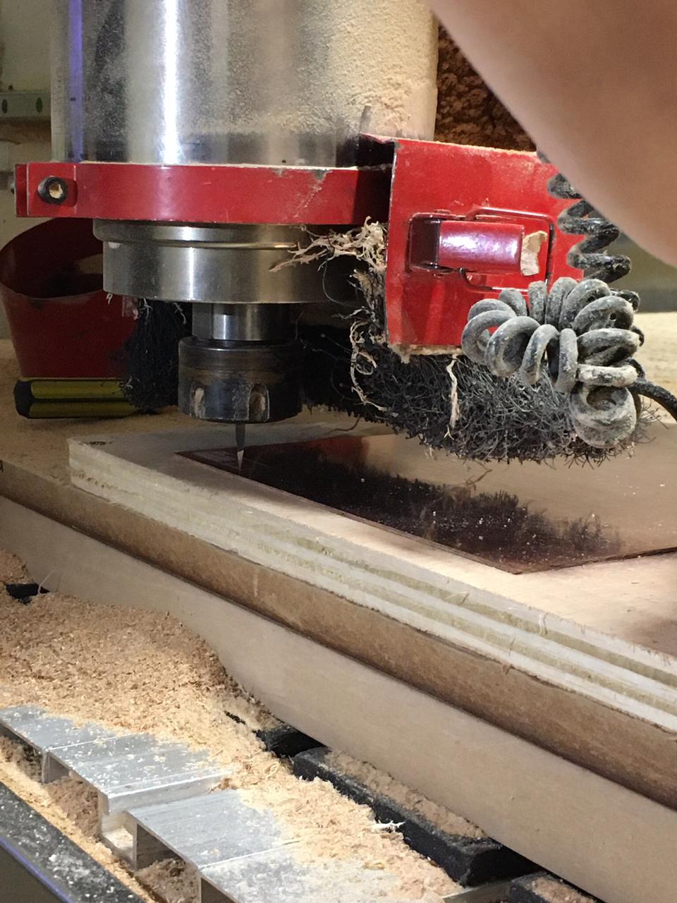
CNC MILLING - WORKFLOW
We used the cnc machine which I find very precise and usefull in so many scales because
the other machine for tracings wasn't working. These are the steps needed to mill the board:
- On the cnc, we used a wood board screwed to the cutting bed
- Hold the copper sheet with adhesive double-sided tape
- You can use an steel wool to remove coats or oxide layer from the cooper and clean it with a cloth with alcohol.
- Place the milling bit
The next step is to cut the outline, to do this it is necessary to:
- Change the mill (to the one with the wider angle)
- Upload the G-code
- Start the milling process
The tools we used for engraving and cutting the board:

worflow to send the file to the CNC
- Copy the file on a designated folder
- Open the software
- Open the file (first the milling, then the cutting)
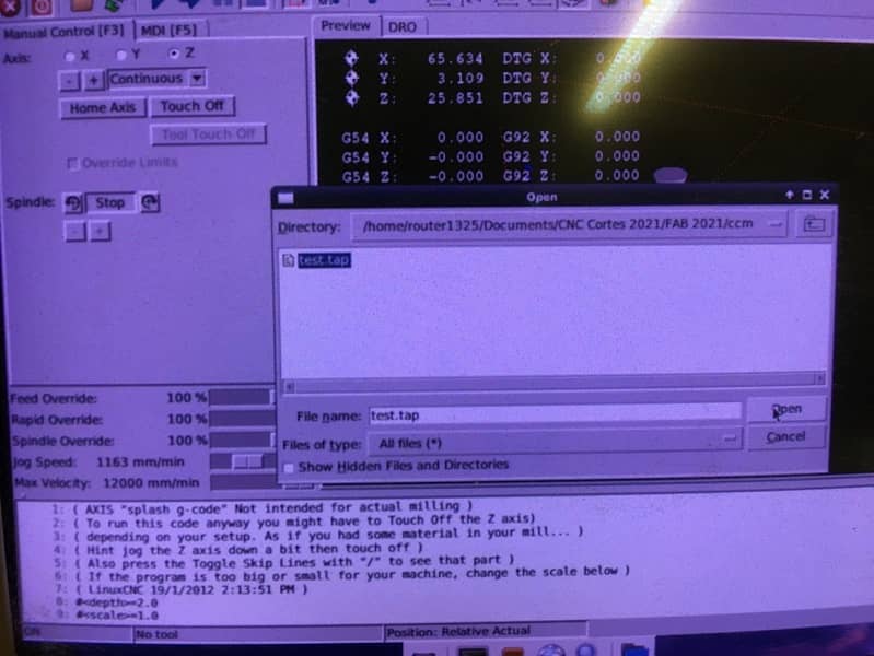
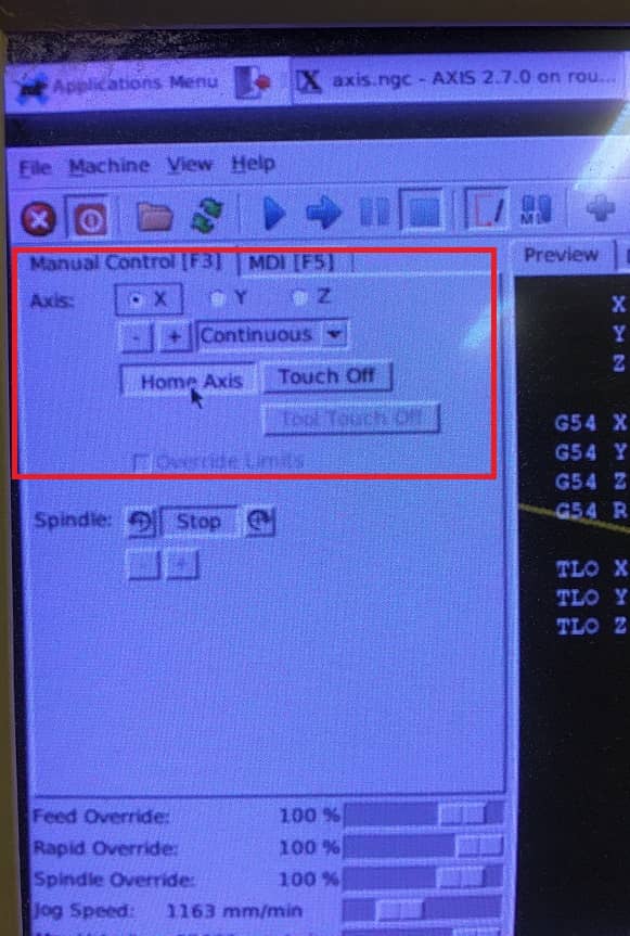
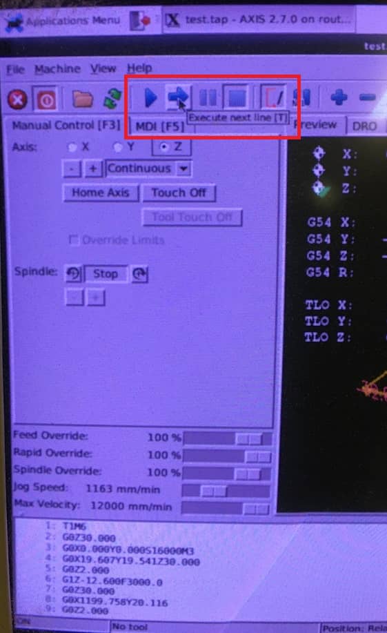
- Use the keyboard to set 0 for x, y and z
- Set zero for xy axis and put auto-level sensor in order to set the zero z axis and moving it little by little until it touches the material
- Run the auto level program, once it is ready, remove the sensor
- Turnon the spindle
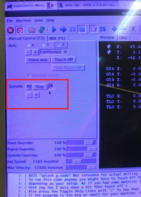
- Start the milling process
- To run the code step by step you can press "T" and to do it non stop press "S"
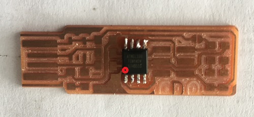
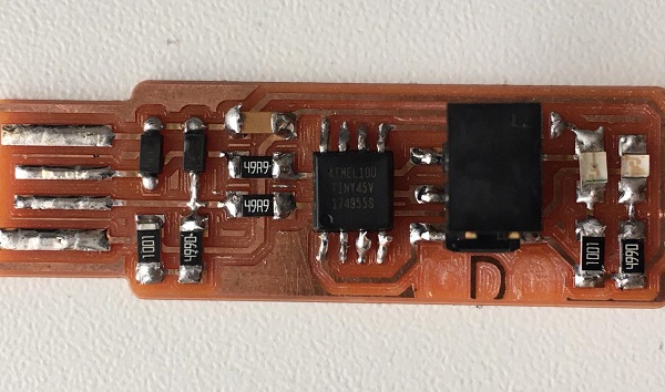
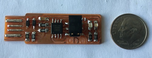
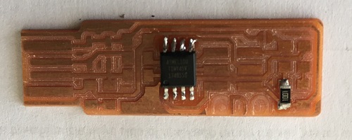
The result looks like this:
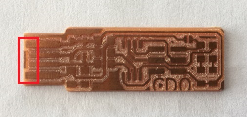
Following the recomendations I removed the bit of copper on the tip
of the board, in front of the usb contacts. I set 3 offsets in the milling process, but it
was needed a bit more. I removed it with a knife pretty easy.
The coper left on the side wasn't necessary to be removed.
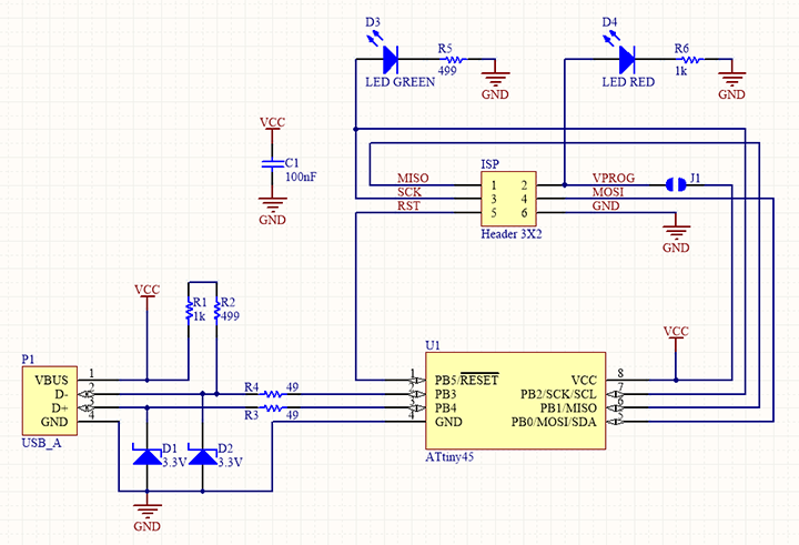
ASSEMBLING THE PCB
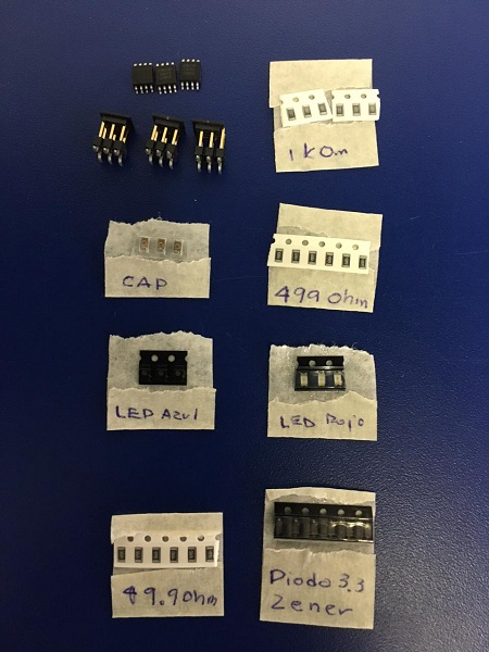
Make sure to have all the components. This is the BOM (Bill of Materials)
- 1x ATtiny45 or ATtiny85
- 2x 1kΩ resistors
- 2x 499Ω resistors
- 2x 49Ω resistors
- 2x 3.3v zener diodes
- 1x red LED
- 1x blue LED
- 1x 100nF capacitor
- 1x 2x3 pin header
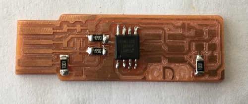
To assembly the parts to the PCB it is recommended to start from
the center towards the ends and from the top to bottom (Reminding Neil's words).
Another recommendation is to start with the most difficult parts, in this case
it would be the ATtiny45 so you can have more accesss for the rest of parts and
leave the IPS header last, because of its big size it can be an obstacle for
the rest of components if you solder it too early.
The ATtiny45 has a dot on a corner, which was easy to find and orient
in the board.
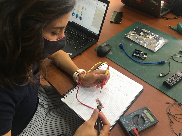
I was told to pay attention to the correct orientatio of the leds and the zeener diodes.
The zener diodes are marked with a green line and to make sure I used a
multimeter to check them.
Added the resistors, starting with the 1kΩ, then the 499Ω and finally the 49Ω.
I confused the resistors and once soldered I had to detach them (a difficult job) and reposition them correctly.
Then added the leds, capacitor, made a bridge and finally the pin header.
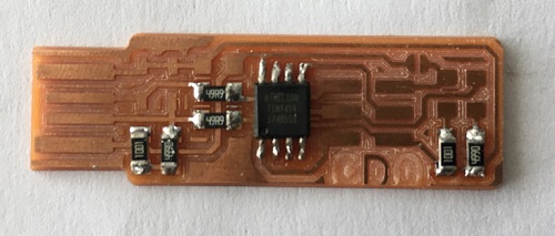
FINAL THOUGHTS
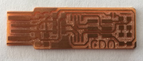
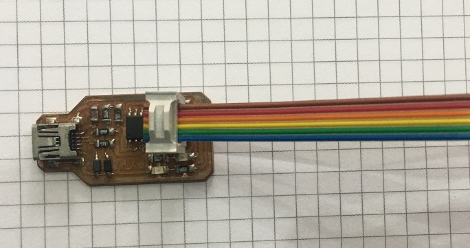
This is the final result of my board after some corrections from my tutor.
Quality is lacking in the welds, it was not an easy job, especially when I had never tried it before.
However I find it interesting and motivating to keep trying. I understand that I still have a lot to learn in this field
but I'm pretty happy with the result.To improve the welds, the recommendation is to put the tip of the soldering in touch of the board and the component
before adding the soldering tin.
I have a nice annecdote, when we prepared the resistor at the lab we mixed the 49.9 and the 499.
I couldn't really see the difference between both of them, so i just followed the example and
assembled my board. Turns out my board was the only one with no mistakes.
PROGRAMMING THE FABTINTY ISP
Alex is a former student very skilled in programming. He helped us in this process.
He has his own programmer which helped us to program ours and gave me the files (you nedd a former programmer to programm your programmer)
Following the instructions from this site Building the FabTinyISP.
In the programming section you can find this link
to install the software needed Using the GNU AVR toolchain on Windows. The recommendation here is to install:
- GIT for windowsWhich I already had installed
- Toolchains for AVR: is a collection of tools/libraries used to create applications for AVR microcontrollers
- GNU make: make is a tool which controls the generation of executables and other non-source files of a program from the program's source file
- avrdude: is a utility to download/upload/manipulate the ROM and EEPROM contents of AVR microcontrollers using the in-system programming technique (ISP)
*Note: had some trouble installing the AVR toolchain, so this site was usefull INSTALL ATMEL AVR TOOLCHAIN
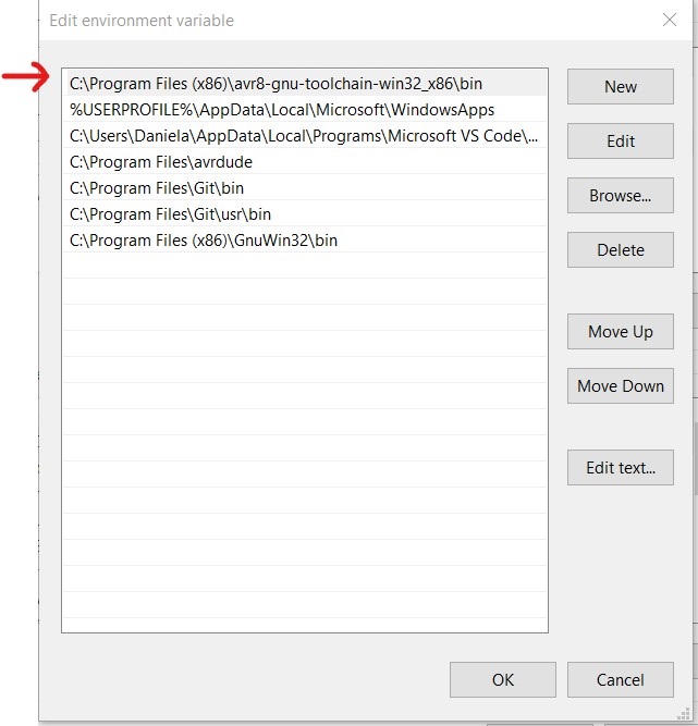
- Then I needed to update the path to tell windows where to locate all the above tools installed. Also followed the instructions provided in the first link of this section.
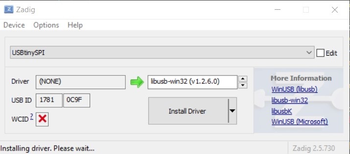
- Next step is to Install drivers for the programmer to do this the recommendarion is to download Zadig and install the driver needed
Sanity check, Open Git bash and type make -v and press enter
avr-gcc --version press enter
avrdude -c usbtiny -p t45 press enter
Notes: * make is working
* avrdude is working
* avr-gcc -- version is not working
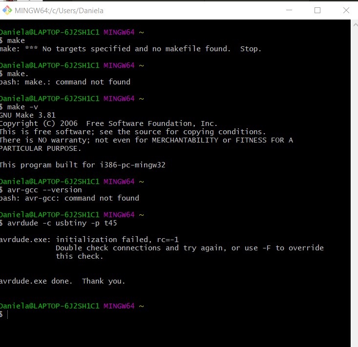
- To fix this is suggested to check the Atmel toolchain and the path variable. I checked the toolchain installed and it was right but the path had the text wrong, went back to this
Site and realized that the downloaded file had the text "master" at the end, edit it, put it on top of the list of paths
and run git again. Not it is working.
In the same FabTiniISP page you can download the make file, then follow this steps:
Programming
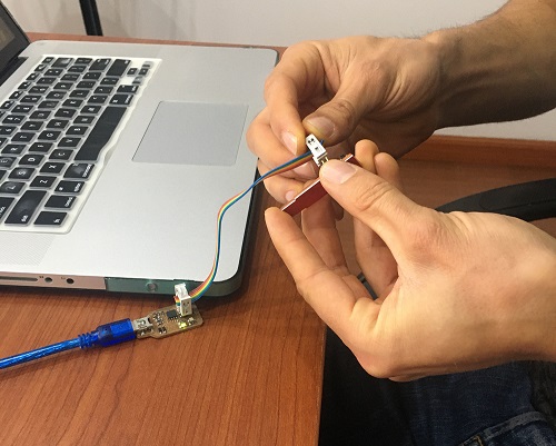
The following video shows a simple programmign I tryed using my outputs board from week 12 . It is an blink exmaple from Arduino IDE.
The connections I made are based on the following diagram taken from electronica guru.
and connected them to my board.
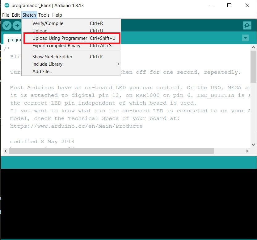
In Arudino IDE, the steps are pretty simple to follow, I found the information in this site Burning sketches to the Arduino board with an external programmer

The following video shows the result:
FINAL THOUGHTS
This has been a week of mixed feelings, on one hand I am excited about the first part of the exercise, engraving the plate, soldering the components, I enjoy this process.
On the other hand, the programming part is still very complex for me to understand (even from the simplest things like understanding what a "hexa" is).
Fortunately, the Building the FabTinyISP page is very detailed and easy to follow and my classmates have been really helpufull throughout this process.
There are many concepts that I find difficult to understand, which takes me a long time to investigate and process little by little, I hope that the next few weeks this improves.


