Week 3; Laser- and vinyl-cutting
making a pressfit construction-Kit after learning the basics about working with the lasrcutter. pressfit has everything to do with knowing about the Kerf and power/speed-combinations of the lasercutter. The way your design will fit is dependent on the accuracy of knowing how the machine works. Next to this we'll make something with the vinyl-cutter and show the result
Weekly Assignment
In my own words
This week we are using the cuttingmachines: the lasercutter and the vinyl cutter. With these machines we have a group assignment and two individual assignments.
The group assignment is to work with the lasercutter and
- Find out what the right settings are for different materials.
- Find out what the Kerf is for out laserprinter
- Make a measurement tool to measure the right width for the gap for a pressfit construction kit. The individual assignment is
- To make a cardboard pressfit construction kit that can can be fitted together in different ways. It should be fully parametric in its design. And . Meaning that depending on material and thickness you can easily adjust the computermodel and lasercut away.
- To cut something with the vinyl cutter.
Planning this week
Due to Corona, we have to split up the group in halves to work in the Waag, I am scheduled to be there on thursday (instruction and group assignment) and on monday and tuesday, the afternoons. I made my planning around this schedule.
| Day | Lesson | subject | activities |
|---|---|---|---|
| Wednesday | global class | make this plan | |
| Thursday | local class | explanation of the machines | Group assignment |
| Friday | 'work' for my work | think of a splendid idea | |
| Saturday | global open time | build CAD model | |
| Sunday | regional course blender 3 | work on CAD-model | work on image for the vinyl-cutter |
| Monday | making final adjustments | Afternoon local Fab time, try and cut out everything | Documentation |
| Tuesday | work | Afternoon local Fab time. Fix everything what is needed. | Documentation |
| Wednesday | presentations | ready to present | fix last things |
Learning activities
I loved the assignment that Neil gave us, It is lovely to do something practical and where there is the possibility to make something that you designed yourself.
My son 'Arend' (dutch for 'eagle') wanted me to make a pressfit eagle. so on wednesday night I looked into pressfit birds. I found that it was possible, but very complicated.
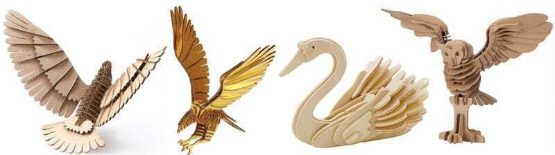 I did think of a way that the feather could be re-usable for different birds and it could have a flying set of wings and a folded set of wings. The parametric assignment could be done for the feathers, overlapping with a standard set of feathers, but it would be to complicated to do this in one week. Especially because my knowledge of the CAD-programs is now very very basic.
then I thought of a second great idea, and My kids were also very enthusiastic about that. I thought of the idea to make a world-globe. the plan was to make the map of the world in such a way that the globe would fit together like a basketball or an orange fits. and then I would make the sea-parts all with living-hinges and the land-parts al with flexures so the map would be flexible in the north south direction.
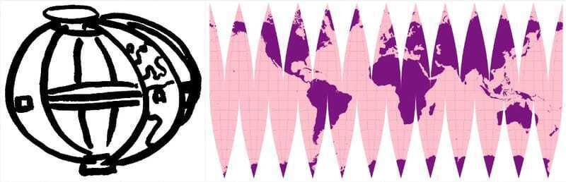 Online I found a great tool to make a worldmap-svg file, so that would help a lot.
So this was my plan, and even going for the extra credits for a board with some flexures
Online I found a great tool to make a worldmap-svg file, so that would help a lot.
So this was my plan, and even going for the extra credits for a board with some flexures
Thursday at the Waag.
Finally we could go to the Waag again. In our lockdown we are only allowed to follow practical lessons on location and learning/using the lasercuter can be counted as practical.
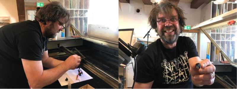
 Henk explained the machines and the operating-software to us on thursday. It was a bit complicated because half of the group was at home and following the class online, and we were only with 2 people in real life. first Henk showed us all the main parts of the laser, with the 100watt laser and the watercooler at the back, and the constructions of mirrors on the side and in the laserhead. He showed us the lens and cleaned it.
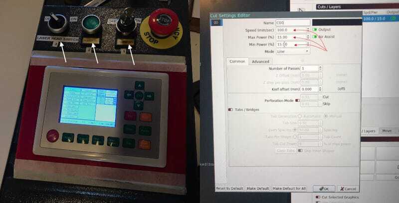
 After learning all about the components of the machine and the main buttons
- on-off with the key,
- turn on the machine with the green button and
- turn on the laser, only when you are about to print with the turning switch(the white arrows).
- Don't forget to 'gently' turn on the fume-extractor/airfilter.
After the explanation Henk showed us some cutting of a piece of paper and cardboard, showing the basic settings of the 'Lightburn'-software. He showed us different settings for the speed, max-power and min-power (see red arrows) while cutting paper and cardboard. Some settings were too low and he showed us how you can let the cardboard burn if the intensity of the laserbeam is too high.
Safety Lasercutter
The lasercutter is a dangerous machine.
- It uses a laser that cuts/fires through the material.
- The machine doesn't stop by itself if there is a issue.
- Basically the machine 'wants' to set things on fire.
So the basic rules that go with this machine are as follows:
- Do not leave the machine, while cutting, always stay on the podium around the machine.
- Only cut materials that are allowed on the lasercutter, for example no PVC.
- After use, wait for the fume extractor to take away all the fumes.
Vinylcutter
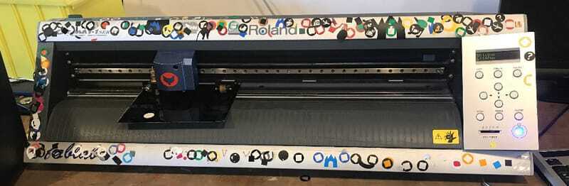
Henk explained the vinyl-cutter and how you can run it in terminal because it is on port LP0 this is also connected to Mods, which you can use to operate it. he showed us how you can cut a circle and that was it.
Group assignment
Luckily there was a third team-member joining us in the afternoon when we did the group assignment. The group was Paula, Philip and Lucia (off and on joined by Sunke, the new facility-manager of Waag) We decided to start with the thinnest and lightest material and work our way up to the more heavy material. We had Paper, cardboard, several pieces of plywood and a piece of perspex. Our plan was to have a nice square ready in lightburn and start from a low power and with every step let the power increase (in steps of 10). The first thing to cut through would be the corners so that way we could find out what the minimum-speed is. After finding a cutting power we would finetune the power downwards and find the lowest possible clear cut through without burning marks on the back.
Paper
First we tested out cutting on paper probably 80 grams:
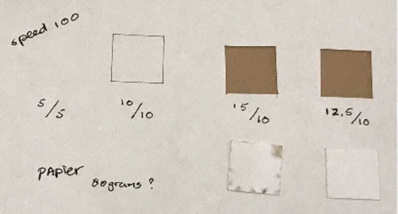
the best setting we found was speed 100 mm/s; max-power 15; minp-ower 10,
or, even a bit lower: speed 100 mm/s; max-power 12.5; min-power 10
Open structure cardboard 2,85 mm
Next up, open structure cardboard thickness about 2.85 mm.
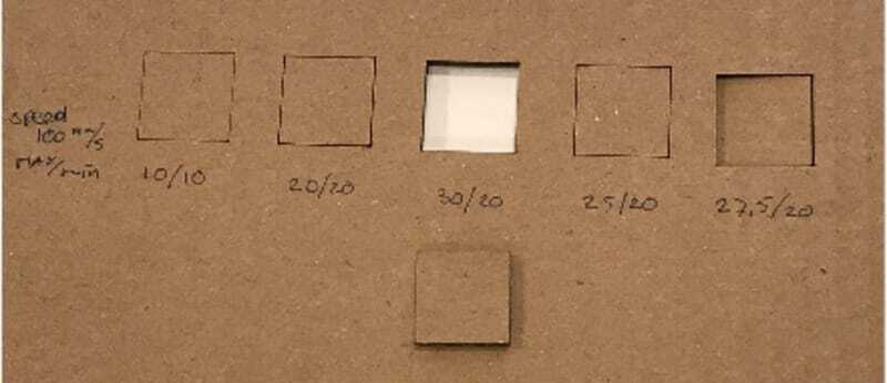
So first we had several tries, all at speed 100. at max30/min20 we had a clear cut. and when we lowered the power to 25 or 27.5 it would still be stuck on some spots, so our perfect settings were speed 100; max 30; min 20
Dense cardboard 3 mm
A second piece of cardboard was the dense kind that would be the back of a drawing-pad. the thickness is about 3,1 mm
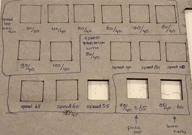 This was all different, We started at the best rate of the much lighter cardboard but that wouldn't even cut through. We could not stick with our plan to keep the speed nice at 100 mm/s and vary the power, because at power 100 we did cut through the corners but not at the middle of the square yet. We did get some burning marks though so we picked our best power-combo (max80/min40) and lowered the speed gradually. and with speed 55 we finally cut through. We tried playing around a bit, but getting burn marks. We found our perfect fit at speed 55; max 80;min40
Plywood 4 mm
we were on a role, here comes the plywood:
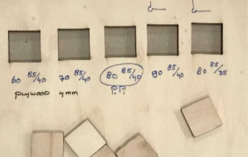 The plywood cut easier than the dense cardboard, which is logical, because there is a lot of air in the wood. The same settings as the cardboard would cut through easily. We played around finetuning the settings and found that speed 80; max85;min 40 would do the trick without too many burnmarks.
Plywood 9,3 mm
Last one up: plywood 9,3 mm. thick
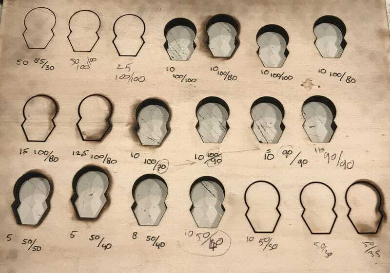 we could have guessed that this wood did not really want to get cut, because there were quite some burningmarks on the edges already. but we tried and tried. We did cut throught at maximum-power and speed 10, but then, when we lowered the minimum power our board started burning. So we tried to change one of the variables but we never got it really to work. We set the board on fire five more times. After a lot of discussion we found that speed 10 max power 50 and min power 40 made the best cut, although still with some burn-marks on the back.
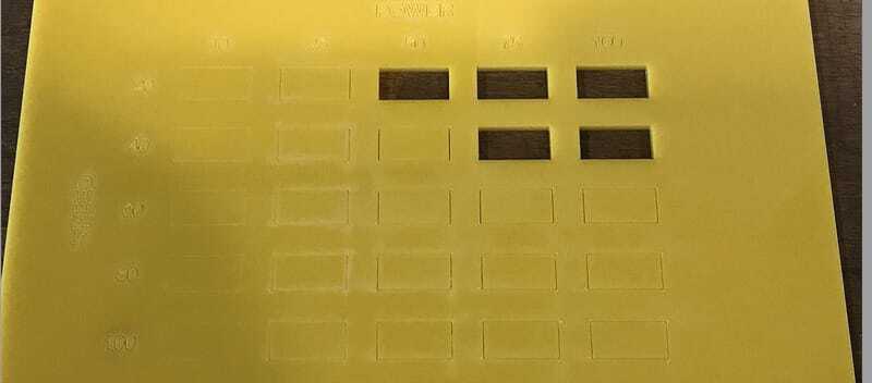
Acrylic
Our time was up, so we did not doe the acrylic anymore, lucky for us, the other group (on friday) did do that for a 3mm thick acrylic plate. With power 50% and speed 20mm/s it would cut through and increasing the power and speed it worked also at power 75 and speed 40
Measuring the Kerf
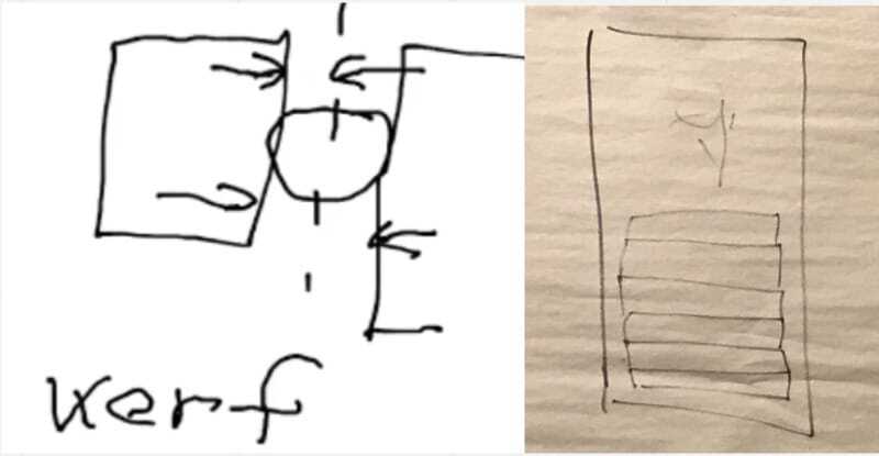 Neil explained about the Kerf and Henk gave us a helpful design how to measure it.
so we cut this rim with 9 loose pieces in it. Moving them all to one site and then measure the gap that is on the other side. it was 1.52 mm so the Kerf would be 0.152 mm. We had quite a discussion about the meaning of the word 'kerf' it being:
Neil explained about the Kerf and Henk gave us a helpful design how to measure it.
so we cut this rim with 9 loose pieces in it. Moving them all to one site and then measure the gap that is on the other side. it was 1.52 mm so the Kerf would be 0.152 mm. We had quite a discussion about the meaning of the word 'kerf' it being:
- the whole section that is cut away and thus measuring 1/2 the kerf if you want to offset your cuttingline (so the diameter of the circle that the laser would cut away if not moving)
- the measurement between the middle of the laserbeam and so being the offset and if you make a gap like we do use 2 x kerf. (so the radius of the circle that the laser would cut away if not moving) the easy thing is that in Dutch it would be 'zaagsnede' and that would be explanaition 1
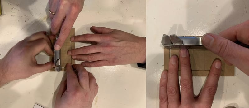
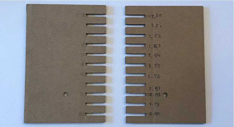
Making the pressfit-measuring-comb.
Due to a mistake I made counting with the milimeters and tenth of mm, we made the right measuring-comb at once, but it was smaller than was planned. but with good luck we did not have to do it again. We found that in order to make the
Combining it all
Than we thought about the results and how to use it in a practical way.
friday, a new assignment idea
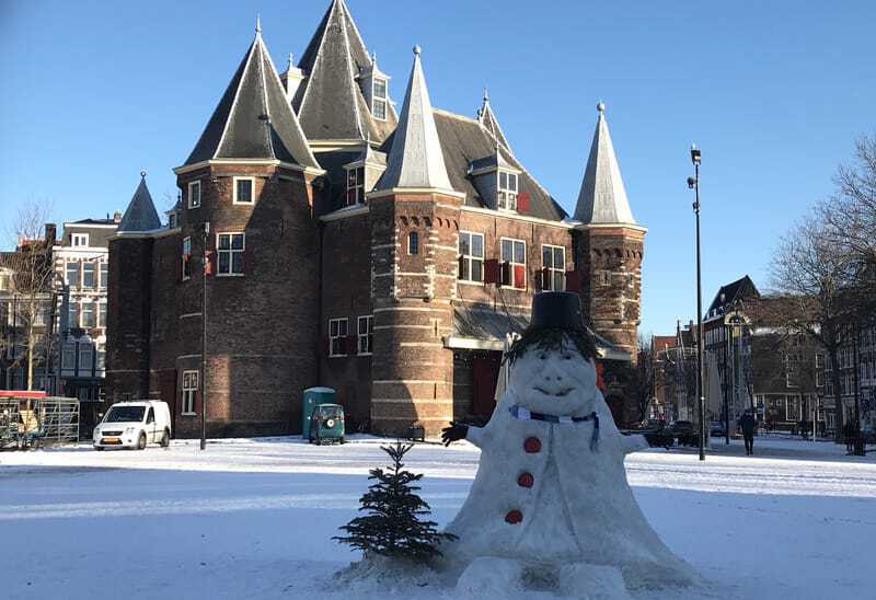
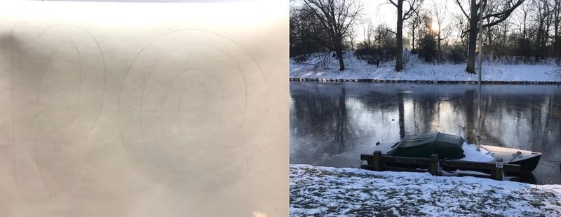
In the Netherlands there is a whole lot of snow and Ice this week, it is blocking the roads and everybody is sledding and skating on the canals. On television I saw a program 'Atlas' about scientific knowledge of the things that happen in the news and there was a professor who explained everything about snowflakes and how they are build up.
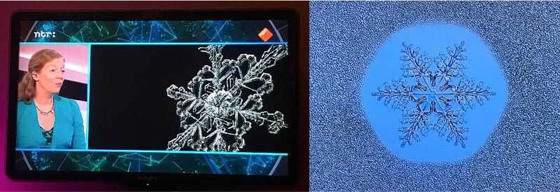 She explained that a snowflake is always a variation on a Stellulair dendritic structure and the ice will only split up in corners of 60 degrees. So with this knowledge I could work with basic shapes and make my own snowflake-building-set.
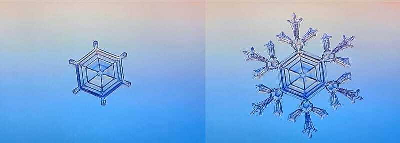
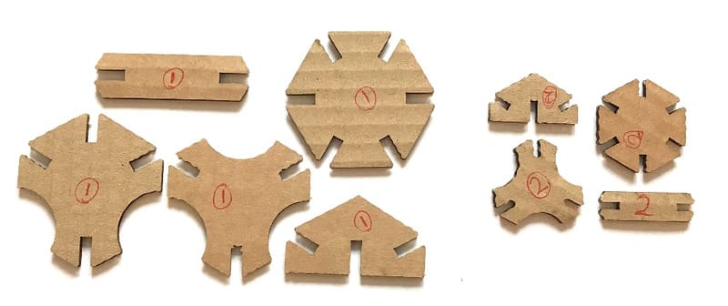
In bed that night I drew my first ideas on a piece of paper and concluded that everything could be build up out of a hexagonal with on every corner a slot or gap that would join to the other pieces.
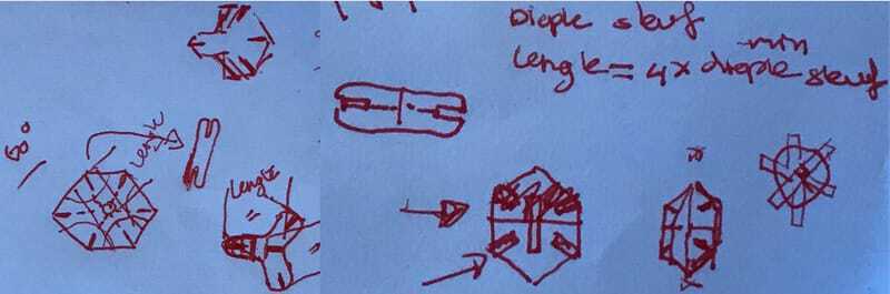 When I looked at it closer the next day I made some variations on my first idea, but still it would all be based on the one hexagonal.
First Experiments for the assignment
FreeCAD
Because Neil explained the pressfitconstructions very clear in the lecture using FreeCAD-files:
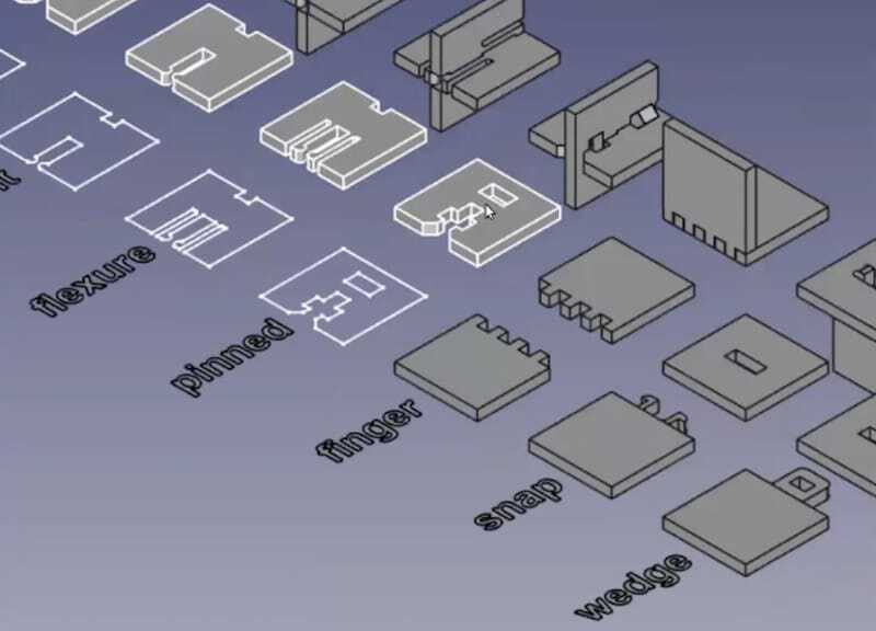
I thought it would be nice to try these different shapes and so I decided to work out my idea in freeCAD.
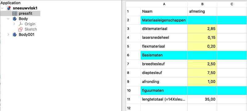
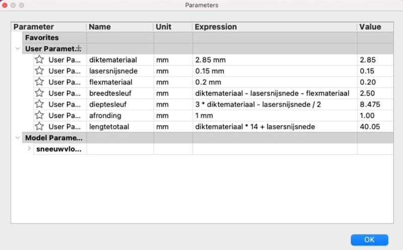
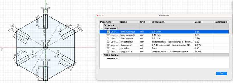
On saturday I worked with freeCAD to get my shape parametric. Luckily I did a series of tutorials on FreeCAD last week and I gave it a good try. First I filled my spreadsheet, I called it pressfit and then gave all the parameters logical names. I already made some of the formula's in the spreadsheet. This would make it easier to point to the right measurements for the different parts of my snowflake. My idea was to make the full hexagonal with the following measurements. Almost everything would be dependent on the material thickness.
parametric design
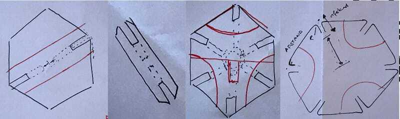
Depth gap
For counting the measurements of the gap I guessed 3 times the material-thickness would hold the pieces in place.
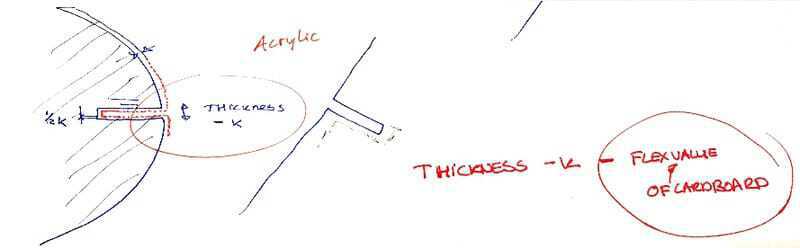
Width Gap
To make the formula for the Kerf and the flexibility of the material I worked with the Kerf measurements that we did on thursday. for one gap I would need the material-thickness - (half the Kerf) * 2 - the 'flexibility-value' of the material. so that would make my most complicated formula: Widthgap = Materialthickness - Kerf -flexmaterial
total size
In order for the pieces not to touch each other in the middle there is some extra space needed. To keep everything parametric it would be logical to take the material-thickness here as the extra space. the depth of the gap is (3 * material-thickness) when 2 slots fit together that would be (6 * material-thickness) adding 1 material-thickness for the extra space. So the radius of the circle that fits around the hexagonal would be 7 X material-thickness. And the diameter 14 * material-thickness.
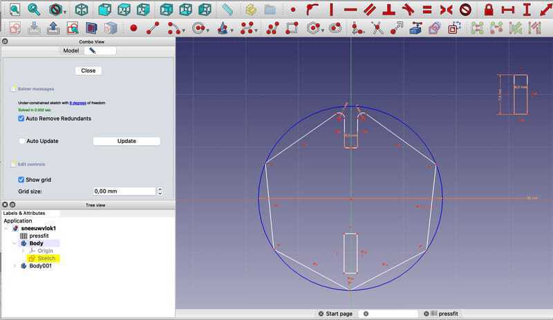
So far the mathematics of the snowflake. now that I put everything in the spreadsheet, time to build. I started with a Hexagonal with the right size. I fit it around the 2 axis with one corner straight up. So far everything is constrained. Then I made a rectangle in the shape of the gap and I was planning to fit that in the top corner and working my way down copying the gap.
But the learnings from my parametric box last week did not help me here, because everything I changed in the topcorner would move things around. The standard constrains of the hexagonal are the equal sides, so if I would cut away a piece or make a chamfer, FreeCAD would recount and fit a shape with equal sides in my circumcising circle.
Everything I tried I always started with one side only and that would move everything around and I ended up with different sides of my gaps. Here in the pciture you can clearly see that the two vertical sides are not paralel anymore.
I gave up on FreeCAD and moved to Fusion360. My learningpoint: FreeCAD is made for mathematcial thinking, Fusion360 is made for thinking like a carpenter. I am more thinking like a carpenter.
Fusion360
So I started again in Fusion360. I could not find a way to copy the content of the FreeCAD spreadsheet, but since it was only 7 parameters I just copied it by hand.
 then I started with drawing the hexagonal and the rectangles for my gaps.
 So far everything is contrained and parametrical.
The boolean operations that I would need to make the gaps, the fillets or chamfers would not work. I could not keep everything parametrical So I was working like a carpenter.
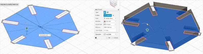
I first extruded the shape that I selected in the sketch (to material-thickness)
So far everything is contrained and parametrical.
The boolean operations that I would need to make the gaps, the fillets or chamfers would not work. I could not keep everything parametrical So I was working like a carpenter.
I first extruded the shape that I selected in the sketch (to material-thickness)
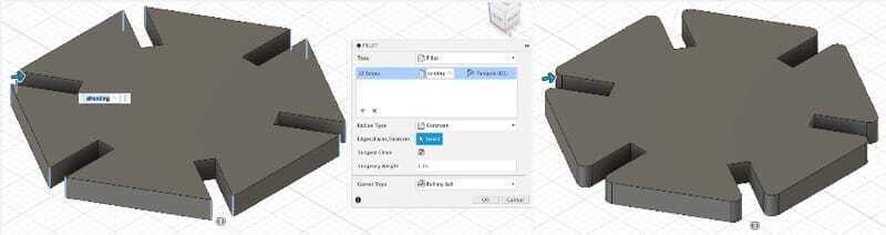
 then I added the chamfers on all the edges.
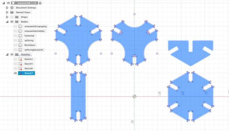
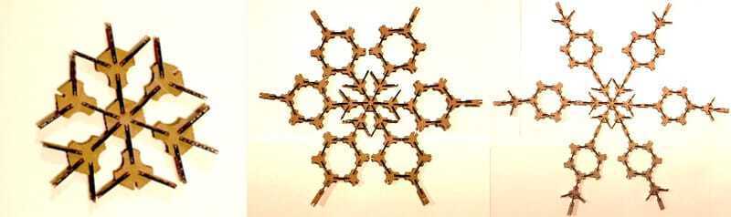
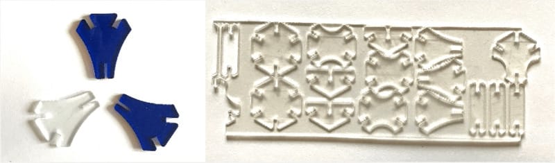
Everything still working parametrically and now I can vary the different shapes I want in just the same way. I need quite some extra constructionlines to get everything constraint but I end up with a nice set of snowflakes.
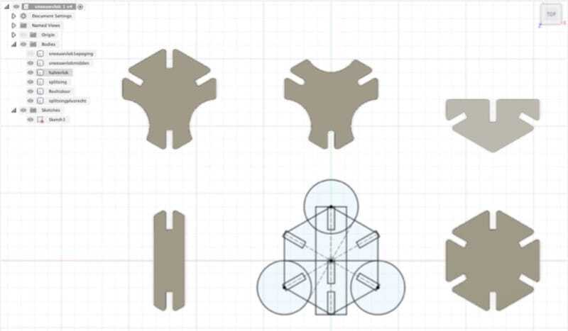
In order to export them so I can lasercut them I found that you can select one plane of one of hte flakes and make a sketch. Then 'project' all the other shapes in the sketch and although it looks funny All of the outlines are there and the sketch can be exported as a DXF file.
Working on the machines
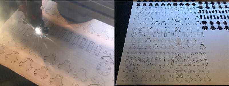
First I did som tries cutting my design. I set the machine to our 'perfect settings for this kind of corrugated cardboard' 9which we found last week: speed 100; max 30; min 20.
At my first try, the cuts were great, but what I did not realize was that I changed the size to show my husband the parametric design and the thickness was still on 4mm, so the first try cam out very big. the second try was tight, but the chamfer (1mm radius) was too small. so I increased the chamfer to 1,5mm radius and it worked fine. After that it was production that I needed. because to build somthing, you need a lot of pieces.
first test at home
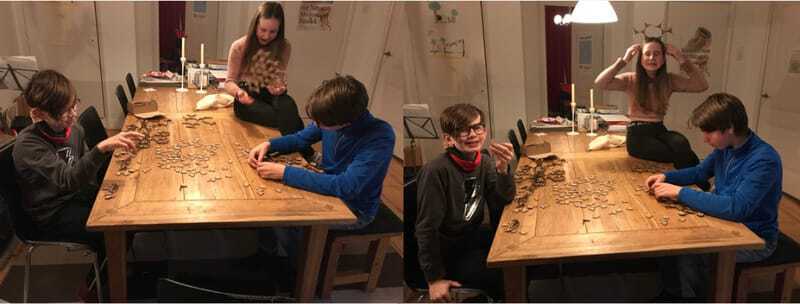
My kids were really enthousiastic and started building right away. They came up with some new designs and on tuesday I printed those as well.
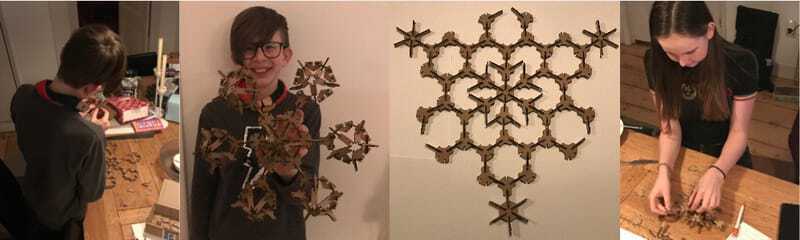
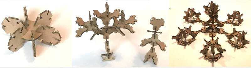
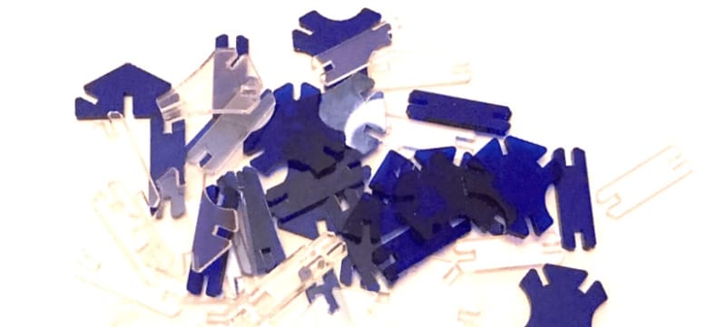
the result
We had a nephew to stay over and with the three of them they build beautiful 2D and 3D flakes.
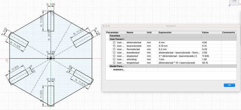
 to see if my design was really parametric I decided to also work with acrylic, I found some small pieces that were 3mm thick and tried to cut first my small set. Set my parameters to 3mm thickness, same Kerf and no flexibility.
I looked at the acrylic-settings that the other group-assignment was at (speed 40 maxpower 75 minpower 75) and cut it straight away. To my surprise it worked in the first try.
to see if my design was really parametric I decided to also work with acrylic, I found some small pieces that were 3mm thick and tried to cut first my small set. Set my parameters to 3mm thickness, same Kerf and no flexibility.
I looked at the acrylic-settings that the other group-assignment was at (speed 40 maxpower 75 minpower 75) and cut it straight away. To my surprise it worked in the first try.
failures and learnings
I did one go with the acrylic and it was a bit bended in the lasercutter, so partly the laser was not focussed, so I have a very nice board with the pieces still fixed in that.
Working on the vinylcutter
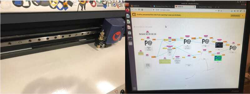
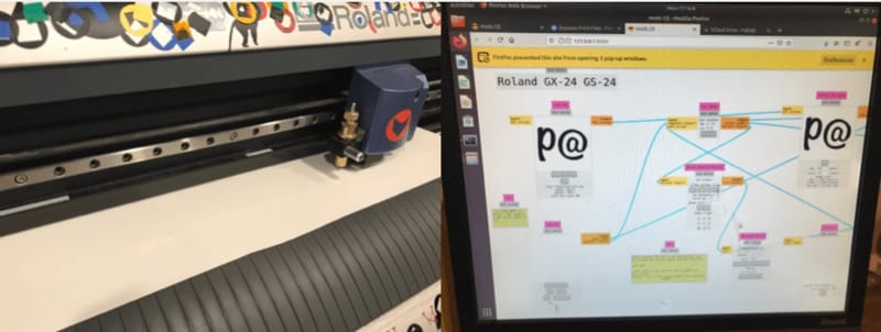
My first try on the vinylcutter was 2 letters, 'p@' which is the name of our little sailingboat. I converted the letters in illustrator to shapes and made outlines of 0.001 mm. then I exported it as a SVG, and tried to upload it in mods. (quite hard to work with if you forget your mouse) but although it was fine on my own laptop, it would not upload on the computer that is connected to our vinylcutter.
The group that worked at the Waag on friday also found this problem and had a solution. In the SVG file you should add width="number" and height="number" the numbers you could find in the viewbox. It took me several tries but finally got it right.

So I found myself a nice shiny white vinyl fixed it in the vinylcutter. Therefore putting it at the back and putting the small weels at the widest possible white points, the lasercutter then asks if you have a roll a, saying okay it will measure the width and is ready to go. The material seemed thicker than most vinyl, but since I did not have any idea of the difference and there was no label or anything, I thought I start with the same settings as the other people were cutting on. I realize that I still need to learn a lot about the settings of the machine. BUt it worked this time.
 I found out that this material was not a sticker and ended up with a great windowsticker of these letters. great for parties and playing around in the car, but not very useful as a name-sticker on a boat.
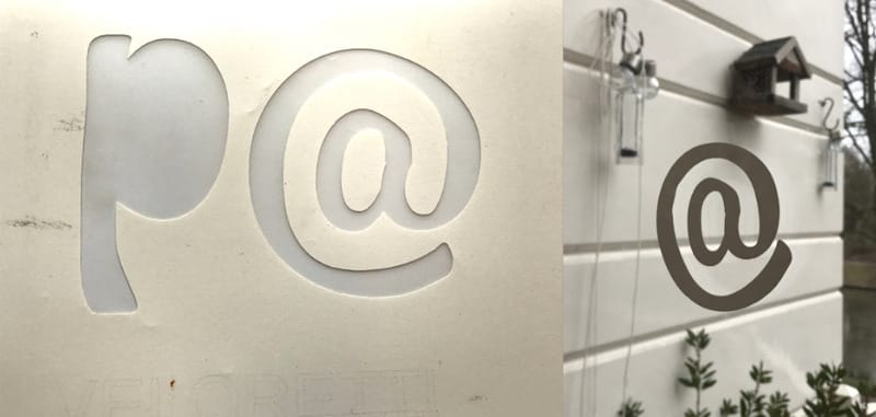
I cut it again with a different role, with the right material... Looks the same, a little less shiny. Sadly enough it is not possible to put it on my boat yet, because the weather does not allow me to go on the boat. I have everything at home now and will wait for spring!
Learnings this week
It was great that we really got to work on making real things:
- It was very interesting to do a group project with such a diverse group. I really felt like having to do experiments again at high-school and Uni, And I liked that. I do not have the feeling though that everybody in the group understands everything.
- Making everything parametric is quite difficult during the design. Because you don't know what measurement is the best to start from. I noticed that for me it really works best to first make some sketches on paper. With that decide what the main measurements are and and only then work everything out in fusion.
- making everything parametric is also very great, because I could change my design in 2 minutes to acrylic and a complete different material-thickness. That is so very cool
- I tried freecad again (because Neil is so enthousiastic) but could not get it to work for me. I am happy that Fusion is a better fit.
- I feel that my knowledge of the vinyl-cutter is not good. afterwards I found that somebody had fiddled with it and the knive was not tightened. But that really set me back.
links to CAD-files:
here are the links to the designfiles of this week: