Final project, the process page
These weeks is all about working on the final project, week 16 getting a good overview of all the different parts needed. Week 17 work in progress and week 18 finishing it al to give a good presentation.
The process in week 16, 17 and 18:
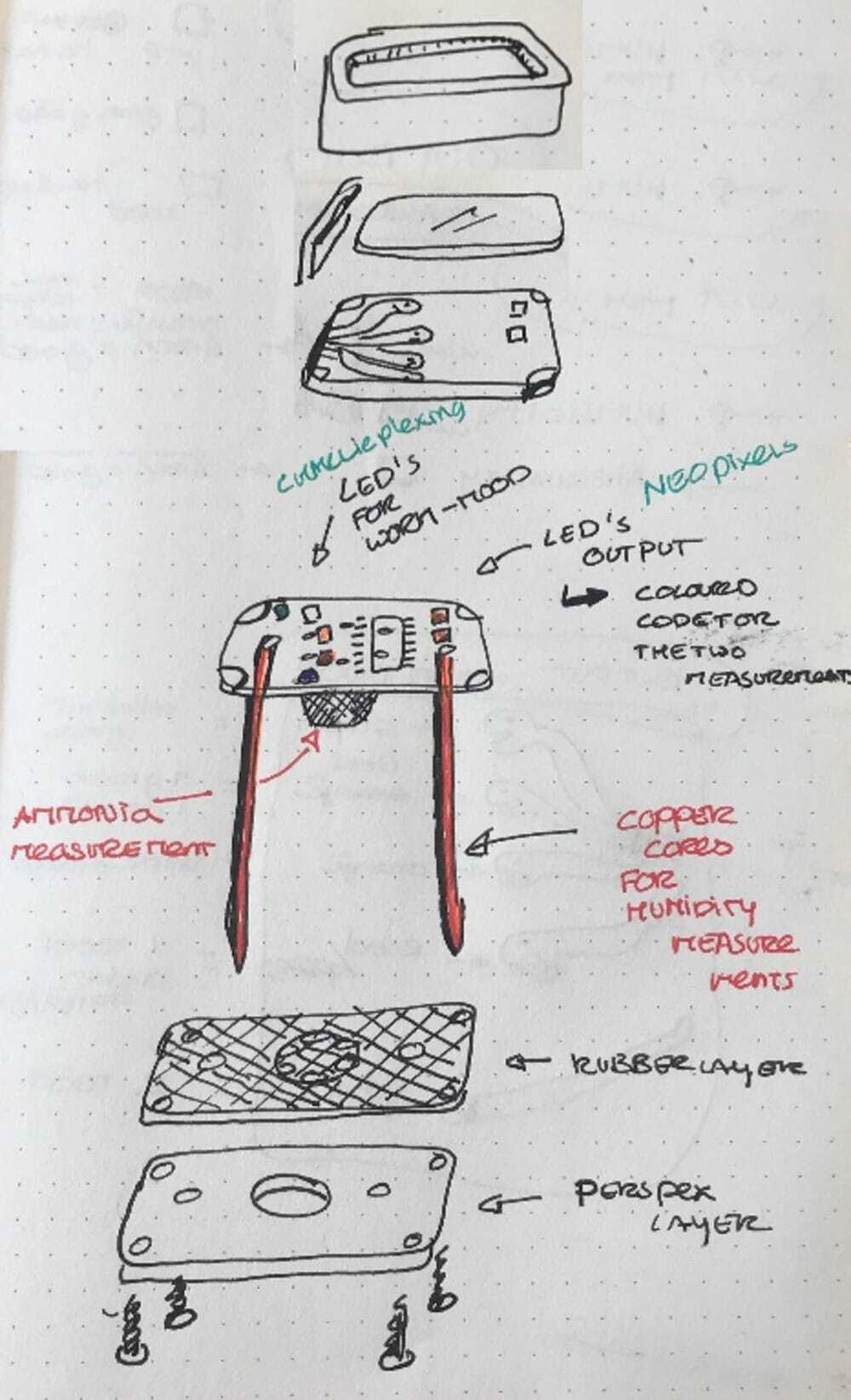
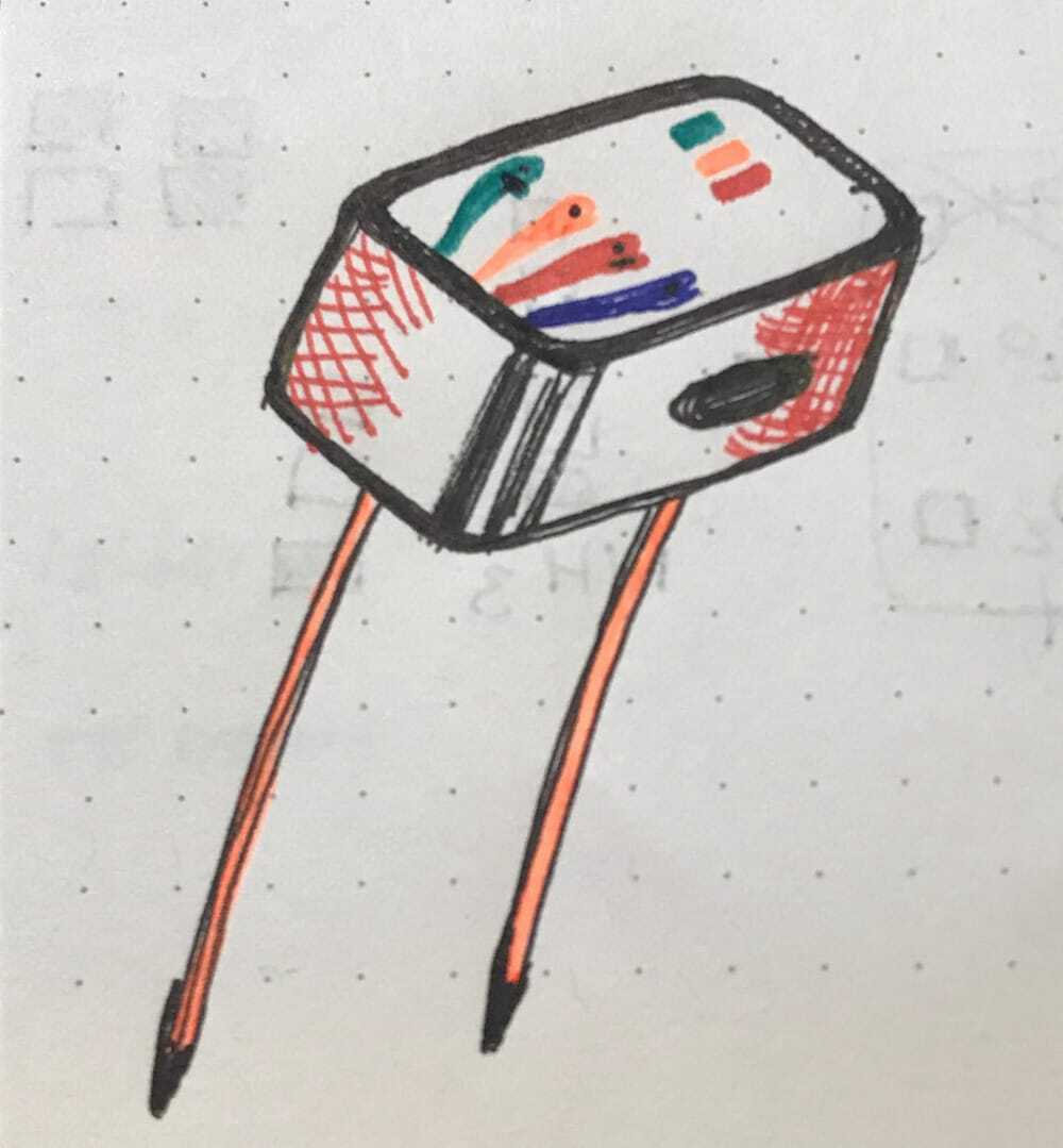
So the basic design is finished, I worked out a plan where my sensors will be on one side of the product (the bottom) and the output will be on the top. for more information on this, see the page of
week 16
week 16
Form follows function
I learned during my studies in Delft that there is always an interaction between the technical product and the shape and usability. So to make the process clear I will first understand the technical part and from that design the housing.
I started with collecting and understanding all the technical parts, so I can make a technical design, after this I want to make a electronics design and mill/solder test that. form that on I can make the final design of the product and probably a redesign of the electronics so I can make everything fit in snuggly in my product and make the inside and outside to a nice integration.
Thursday Waagtime
I wanted to test the different acrylics for my screen, so I took my drawing of week 3 and played around with the lasercutter and the different scrap-pieces of acrylic that would maybe be nice. I worked out what the right settings would be for the cutting of 3mm thick acrylic and worked out what the best way would be to have the engraving of the worms.
- the settings for engraving without cutting through the board at the coreners of the drawing arespeed 50 power 50 and minpower 15.
- the settings for cutting it nicely are: speed 40 and power 80
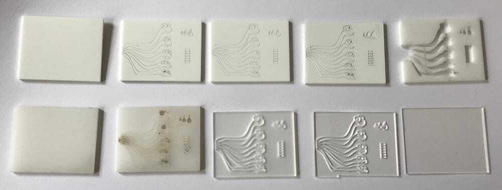 I learned that I have to simplify my drawing and take out all the double lines to get a move even result without burnmarks.
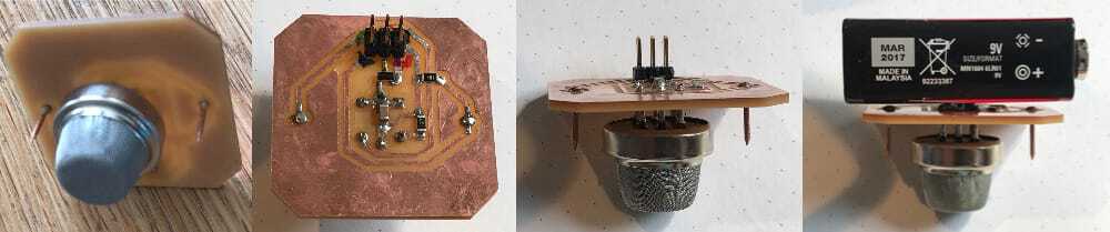
Moisture sensor
I got this chinese made sensor for measuring moisture and found online quite a lot home-build sensors.
- sensor with nice explanaition
- very simple sensor with two nails
- nice explamaition on how to build your own moisturesensor
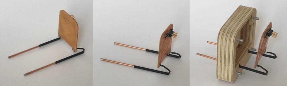
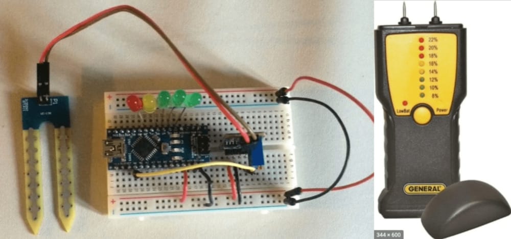 So I would start with this generic sensor and hopefully end up with my home-designed moisture-sensor, which will also function as the legs of my product, to stick it in the compost for testing.
 - explanaition of arduino-moisture-module
The different examples of home-build sensors were all talking about corrosion on the pins, especially because there is a current going through them. The solution is to only measure shortly and not too often. This fits my desire to be efficient with the electricity and changes my design a bit, I will not give a continuous repeating measurement, but only when you ask for it.
deep sleep mode
I worked for a bit on the sleep mode, asked Erwin, found some info on avr-freaks
I need to use a Interrupt button, that can only be on certain pins. Button asynchronous pin. The rest is coding it. that is enough to work with for now
Ammonia/sulfur sensor (air quality.)
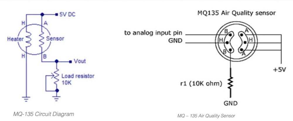
I bought the mq135 because it is a much simpler sensor than the Ph sensor I was looking for. I looked for an arduino-example online and found several good examples.
- basics about measuring with MQ135
- explanation with datasheet of MQ137 (which works on the same principle)
- explanation with circuit and code of MQ135
- nice and good explanation also with pin-instructions
Here I found these good examples of the circuit i need.
I hooked it up with my Arduino and it gave a score of around 400. I found that you have to preheat it for either 20 seconds or 24 hours. I really have to look into this.
Sensor and battery
My plan was to use a cr32 button battery and a step-up to make it 5 volt. The battery would drain quicker, but the product would stay nice and small.
First I went to the action to see if I could find a nice product with a 4,5 or 5 volt battery-pack, but I did not find anything.
Then I went to my local electronics shop, Henk (yes also Henk) told me that I would not get enough current from the coin-battery to power the gas-sensor. That made sense, because some of the Arduino-tutorials were also talking about powering it separately.
He advised me to go back to the Action and get the smallest powerbank, because it would have enough power and has a 5volt connection build in.
I was quite disappointed, especially because there was a huge line in front of the Action (due to the corona-rules) and I did not want to spend my afternoon cycling back and forth to the Action.
I looked online to their powerbanks assortment, but they seem quite big, or the shape is not fitting my idea at all.
I looked at the electronics and battery-packs/powerbanks at home and online and found that a 9volt block battery might do the trick. It has the right shape, and is quite powerful compared to its size. And I would only need one.
Certainly worth asking during open time. I have 3 questions:
is it possible to use this 9 volts battery? (And if not, what then?)
 Is it possible to use the (big) regulator in the home-set to reduce the voltage?
Can I power the sensor through the AT-tiny or should I power it by itself (I think the latter) How do I connect the sensor to the circuit if I cannot let it go through the board. I don’t want it to drain the battery.
Is it possible to use the (big) regulator in the home-set to reduce the voltage?
Can I power the sensor through the AT-tiny or should I power it by itself (I think the latter) How do I connect the sensor to the circuit if I cannot let it go through the board. I don’t want it to drain the battery.
Open time
It was a great discussion, Adrian wanted me to use the sensor-module , but that would not solve my power-problem. I did promise that if I did not get it right, I would use the module. In general; I learned a lot.
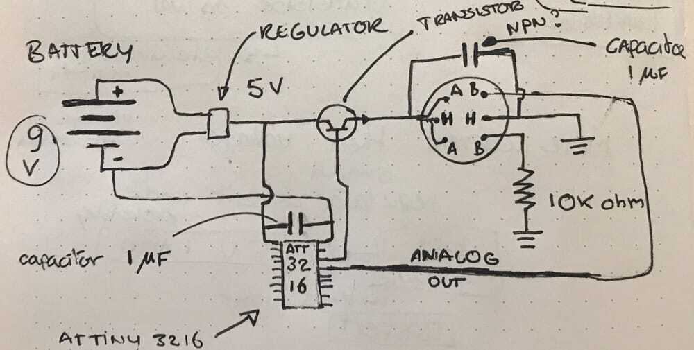
Adrian made a great drawing of how it would work with a regulator and a 9 volt battery:
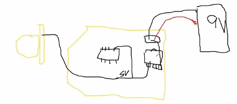 The 9 volt battery could give the current, but I would need the big regulator. I learned about the 150-200 mAmpere of current that the heater in the sensor would take. I learned about regulators and about putting extra capacitors in place.
and with all that information I made a new sketch of how I would hook up my sensor.
The 9 volt battery could give the current, but I would need the big regulator. I learned about the 150-200 mAmpere of current that the heater in the sensor would take. I learned about regulators and about putting extra capacitors in place.
and with all that information I made a new sketch of how I would hook up my sensor.
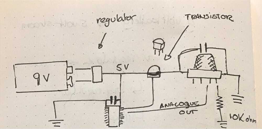
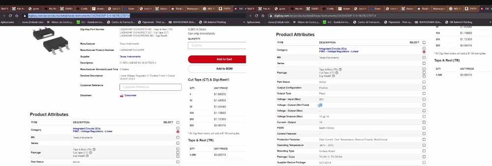
I looked in the fab-inventory and found the 5volt regulator that would fit, I looked up on digikey what I needed for that and it seemed quite straightforward.
Also we looked into the idea of heating the sensor for 20 seconds before measuring it 24 hours. I found some site on these mq-sensors that explained that you should heat it for 24 hours the first time so it would work accurately and then preheat it shortly to do the measurements.
- difference between 24 hours preheating and 20 seconds preheating
- this site realy explores the what and how of the sensor
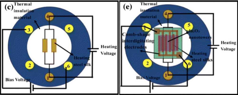
and a good explanation of the how the sensor is build up internally:
Kicad
Trouble finding through hole sensor,
Through hole single holes footprints
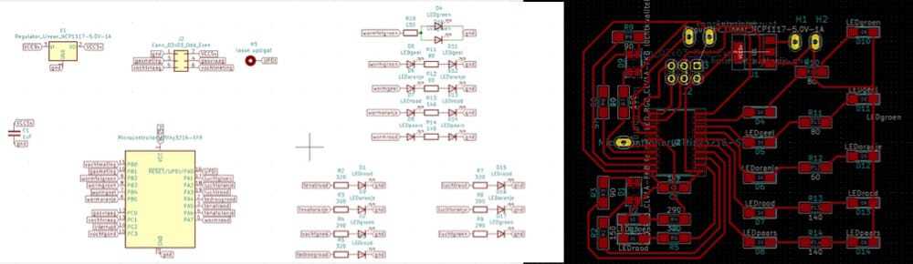
I first made a schematic with all the parts in it, in order to check if everything is there, then I started working on the pcb I realized that I wanted to split it, but it was impossible.
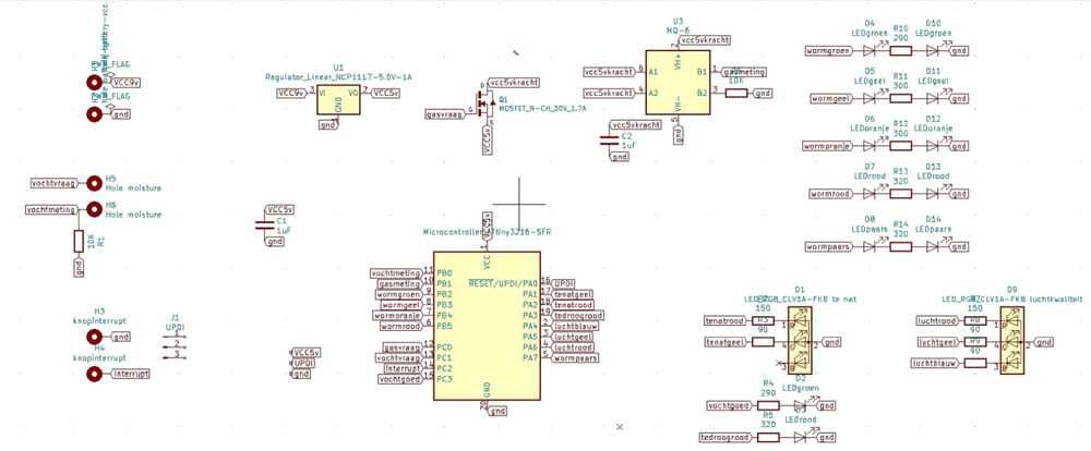
So eventually I made a new project ‘sensorworm’ and put the ee-scheme of my total project in there and that worked. I deleted all the components from the other board and made two seperate eeschema's:
- one for the main board:
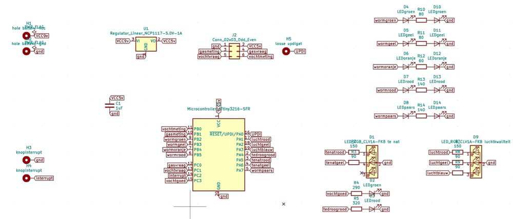
- one for the sensorboard:
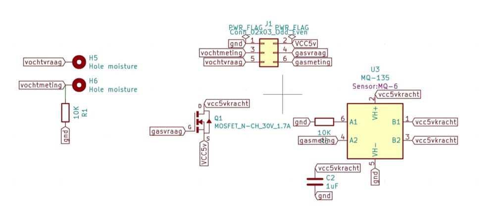
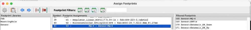
Then I started working on the pcb, but it was impossible to find the footprint for the through-hole bits.
That way they can stick out in the other side of the board ans so save space for my battery.
It took me really long but I found a mq6-sensor in the standard library with a footprint.
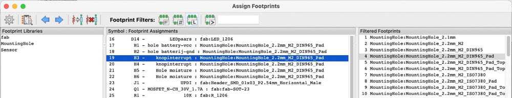
 I want to make my sensors ‘through-hole’ and the connection to the 9v-battery and the pins for my connection cable. I could find some mountingholes, but they would not show up in the pcb as a footprint. This program is really not working nice.
Which resistors will I need.
Working out the resistors for the LED’s
I want two LED’s for every worm, that means that I have to find out about the resistors that I’ll need.
With the digikey information I found the current and the voltage-drop for every color LED and made a nice overview using a calculator of what I need.
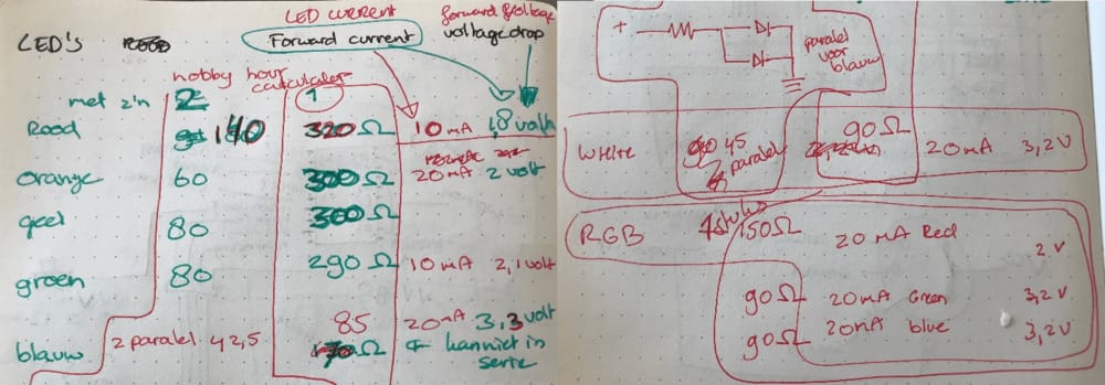 Also I’ll need different resistors for my RGB LED’s
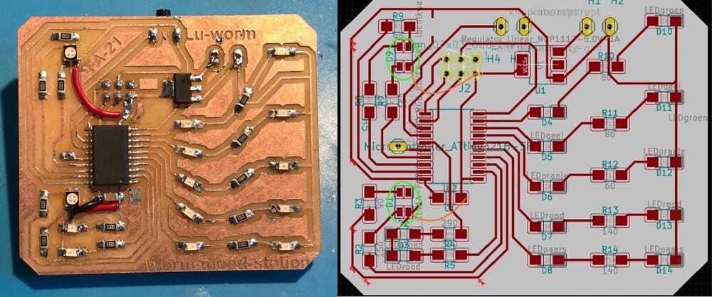
After a lot if cursing and fighting with KiCad, I got my PCB’s ready.
The main board is getting quite full and in order to connect both boards I decided to change the layout of my 6-pin connection. That way I can route the pins nicely next to each other to the connector-pins on the board and save space. On the sensor board I have lots of space to reroute the lines.

Monday Waag-time.
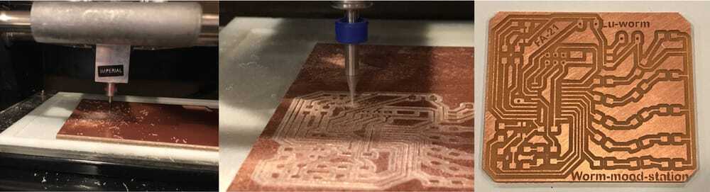
Time to mill, my design is functionally ready and now it is time to mill and see if the electric scheme I made is working.
 I put the while design in illustrator and made another layer with my worm-line-out on top. This way I can set the LEDs and resistors in the right direction. Selecting both pads of the footprint and using the Rotate tool. It works really nice.
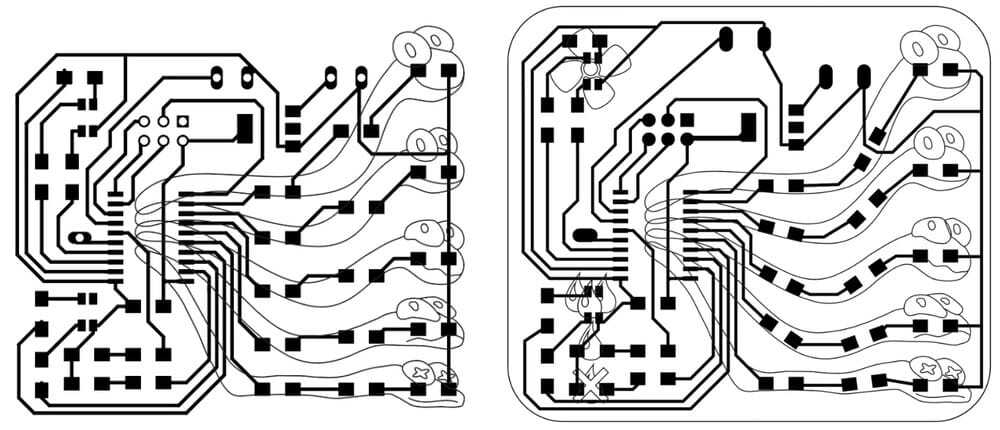
While the sensor-board was happily milling away I did the final adjustment on the main board, adding my name and moving the ground copper core out of the way of the ‘worm-heads’.
From the layer with the worm-outline I made a opal acrylic plate. With the plates that I made on thursday and the new layout from the pcb-layout.
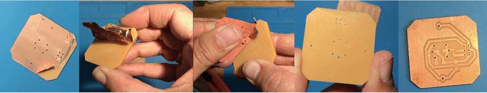
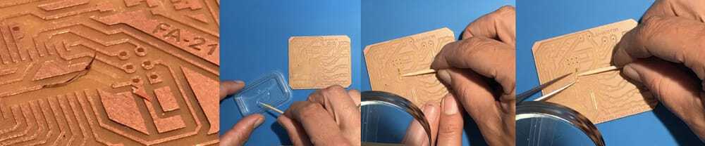
The sensor-board came out fine, 2 little mistakes.
it was a double sided board and since I will stick some parts through the board I will have to remove the copper.
The holes for the through-hole pins are too small, I repaired it by using a 1mm mill and grinded them out by hand.
The big board was ready to mill, Before that I changed the board in the mill to have only one side of copper. First the holes, I did an offset of 2 this time and now it would make nice circles in the board. Great! I figured that making my name in negative (cutting it out of the remaining copper in stead of tracing around it) would give a quick and nice effect, but also would take an extra layer to cut away. I made a separate export for that.
Now the traces, I imported everything, put the right milling-bit in and let it run. It did not make it in time for Henk. He wanted to go home, and he was very right about that ;-). We solved it by putting the Roland on ‘view’ and turning of only the monitor. Henk would resume the milling as soon as he would come in in the morning and I would finish the text and outline after that. Loes has made a reservation for tuesday morning so I’ll have to be early in Amsterdam.
While waiting for the traces I lasercut the screen with the worm-outlines and I tried to cut it with the vinyl-cutter. That did not work out too well, the pressure was too high, the outline would not cut and the small bits like the pupils would be really messy.

Mondaynight,
I felt quite happy for the first time in weeks, because finally I am producing something!
I could finally solder, my sensor-board looks great!
Tuesday morning Waag time.
I came in really early, around 8.30 and the board was almost finished. Henks trick (with 'view') worked. And I could finish it by running the name-layer and outline layer. It came out really nice.
 I found right after milling that I made the space between the coppertraces too small at one spot, where I turned the resistor-pad in the green worm and the ground underneath was attached to it. So I visually checked the rest of the board.
Soldering
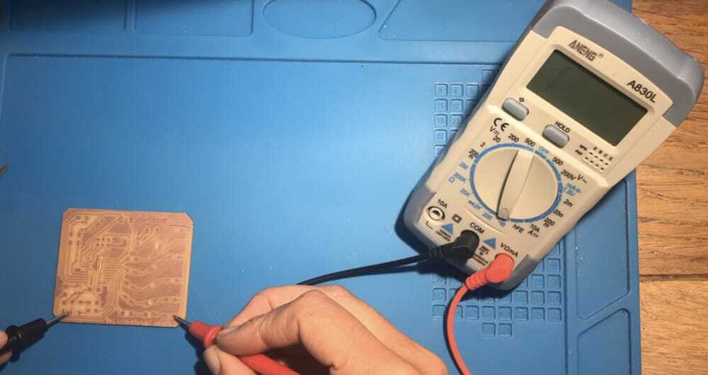
Before soldering I checked the whole board and found the the button pad was connected to the ground. so I cut away some of the trace and then decided that it would be smart to check the whole board with the multimeter for shorts.
When I was carefully peeling away the copper that was left between the traces I accidentally cut the vcc line and pulled it half off.
Hmmmmmm, online I found that Epoxy is the best way to fix it to the board again. Luckily I have some epoxy-glue laying around and since a few weeks quite some experience, so I glued it back on, taped it in place with PE-tape and left it to dry during our local meeting..
 After that I soldered the 2 vcc parts together and added some copper-tape. It was quite hard to get it really flat for under the microchip, and the epoxy would loosen with the heat of the solder-iron, but I did manage to get it fairly nice in place.
really soldering
Now I could finally start soldering. First the attiny3216 and after that all the different resistors and LED’s. I checked them all with the multimeter, just to be sure that i would not turn any of yhe LED!s around. I learned that the RGB-LED has the corner taken off at the Red connector. so I soldered it nicely on the board.
Writing the code
After soldering I was happily writing the code for the whole thing. first I made an overview of all the pins, with arduino-numbers on my print. I gave all the pins a corresponding name. My first plan is to test all the LED’s and check if the resistors I put in, will give about the same amount of light. so I assigned all the LED’s to output pins, but I still have to find out how to control the RGB-LED’s in the code. first I’ll look for a tutorial on that.
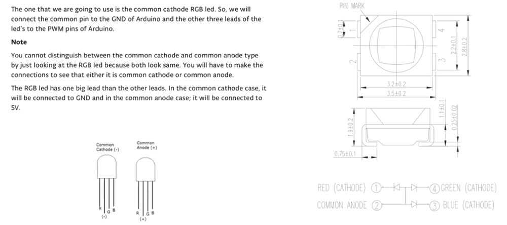
https://create.arduino.cc/projecthub/muhammad-aqib/arduino-rgb-led-tutorial-fc003e I looked at the info and found that in my logic the RGB-LED would have a common ground pin(-), but it turned out that there are two types and our RGB-LED’s have common annodes (+)… I don’t know how to solve this…. for now I can use a bypass on my air-quality-RGB-LED, but for the ground-moisture, it is more complicated, because the ‘common-pad’ is not only connected to the ground, but also to the ground-pads of the other LED’s….. hmmmm.
first I changed the ground for VCC, with 2 bypasses. and hoped that it would work. It would not. The weird thing was, that in my example it would be red, green and blue and in real life it was only red and purple. It seemed that yellow was not connected and red was also connected if blue was on.
pfff, I soldered a separate rgb-led on a 4 pin holder to test how it worked, and found that the vcc should have been on the opposite pin than I thought. and therefor my colors were all screwed up.
 I decided to turn the RGB-LED around for the air-quality. (there I am using all the pins and I would only have to change the names on the pins and in my coding to get the right output. I decided to solder an orange and red LED on the moisture-level, because it is easier soldering and I could test if they would both fit behind my drips-icon. It is much easier to code that, because then the pins could just be digital and on or off.
Testing the board
After doing this I tested the whole thing, it would work, the orange and red LED next to each other worked fine.
But the rgb-led was superbright compared to the others. I tried to dim them , but then found out that these Rgb-leds would not dim on analog ins, only on PWN pins.
Only one of the pins I connected it too can be a pwn-pin.... I soldered bigger resistors in place to dim them. That worked a bit but I could not change the colour.
hmmmm maybe I’ll just go for 3 leds next to each other.
Feedback on the colors
Worm-LED’s 2 LED’s in series with small resistors: the plan with the blue filter over the red LED did not work, and my daughter gave some good feedback. It would be more positive if the really happy worm is a bright green if everything is fine and then make the second worm a little less green, then yellow, orange and Red as the worst case scenario.
resoldering
I resoldered all the LED’s and Played around with different resistors, since some of the LED’s were way brighter than others.
the top green- LED’s I did not get them bright enough, my smallest Resistor is 49.9 in the next version I will make them parallel in stead of in series in the next version. the used resistors now are: Greenbright: 49.9 greennotsobright 100 yellow 181 orange 150 red 181
For the moisture I used only one LED for every color and I ended up using resistors of 330 for all colors. The top red LED is not hooked up good, because it will only show that it is on, but won’t shine, I resoldered it several times tested it separately, cleaned up the trace underneath and replaced it for a different LED, but all that would not fix the problem. Of course this is a messy part of the board because I changed the RGB-LED for the normal LED’s and had to put in quite some copper tape to fix everything. In the next version the design will be prepared for this and hopefully it will work fine then.
Design-Ideas
wood multiplex housing
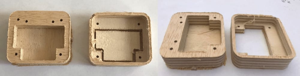
I am thinking about the housing, making it with the 3d-printer would be a nice finish, but making a 'spekkoek'-look with a small and thick piece of multiplex would also be nice, I want to make this on the shopbot, but it really has to look nice and I want the walls of the product to be thin, so it will stay small.
The layers of electronics/acrylic in from the top The battery in the middle a smaller space and the underside separately from the bottom. Something with a piece of rubber for the button and the bottom hokes. The wood can be finished with epoxy, fir a nice shine. Maybe some pins between top and bottom Maybe some fineer-wood for the top and bottom closure
covering the elecronics so the colored LED-light will go only to the right worm.
I tried cutting thin clear acrylic and before removing the coveraheet spraypainting the sides black, so you can see all of the electronics. Maybe an extra electronic plate, with the components 'complaser' holes cut out, so you can see everything.
Button
Rubber layer with 3d-printed button Rubber bicycle tire Eva foam? Is that cuttable on the lasercutter?
New main board
For the second main-board I had to alter several things. I made new layers for on my main board, skipping the whole RGB-LED and making a version with the connecting pins to the sensor-board a bit further to the side so the battery would fit nicely in the middle of the product. I also noticed that my worm-pictures where a bit fat to the side, so I shifted around the board a bit and got the picture more in line with the center. the air-icon could be a bit larger and the water-icons also. so the different LED's would fit behind them.
Friday I went to waag to mill my new main-board. with the altered design. it came out fine, only thing I noticed is that I did not change the place of the button, so now sadly enough it is not centered. I'll have to fix that with my housing-design.
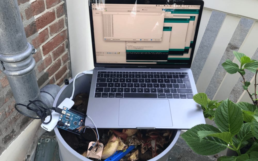
Weekend: Testing the sensor side:
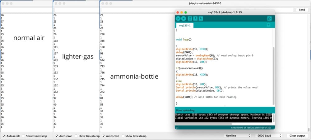
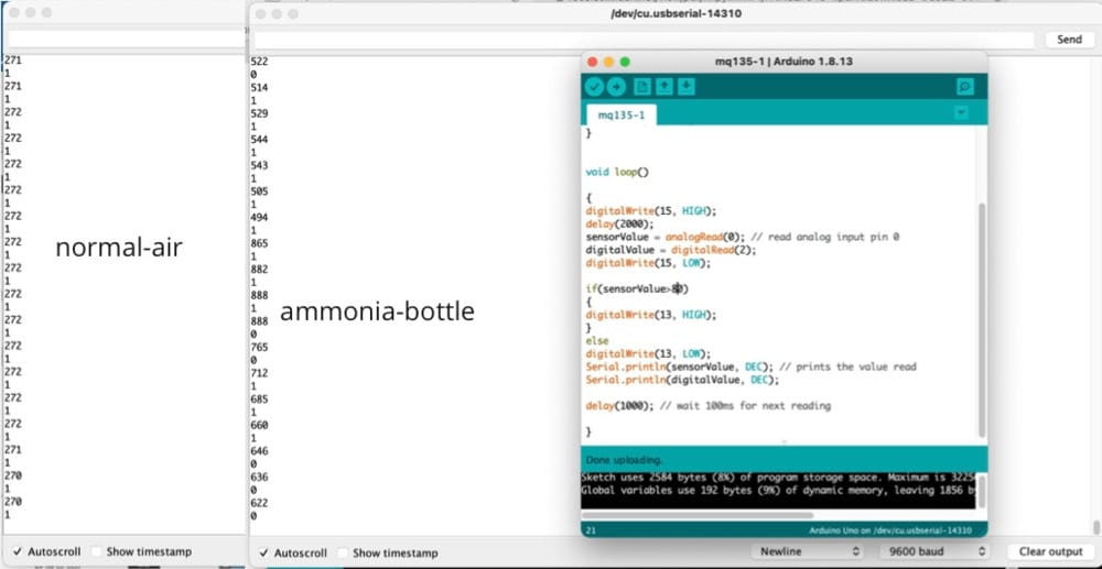
First I connected the good old arduino to my computer and combined it with the bought mq135 module. I found a bottle of ammonia in my basement and a gas-lighter (which is used in all the tutorials.)
The code I used:
 1int sensorValue;
 2int digitalValue;
 3void setup()
 4{
 5Serial.begin(9600); // sets the serial port to 9600
 6pinMode(15, OUTPUT);
 7pinMode(13, OUTPUT);
 8pinMode( 3, INPUT);
 9}
10
11
12void loop()
13
14{
15digitalWrite(15, HIGH);
16delay(2000);
17sensorValue = analogRead(0); // read analog input pin 0
18digitalValue = digitalRead(2);
19digitalWrite(15, LOW);
20
21if(sensorValue>400)
22{
23digitalWrite(13, HIGH);
24}
25else
26digitalWrite(13, LOW);
27Serial.print("air quality: ");
28Serial.println(sensorValue, DEC); // prints the value read
29Serial.println(digitalValue, DEC);
30
31delay(1000); // wait 100ms for next reading
32
33}
It is clear that the the 24 hours stabilisation is needed, because my values are a lot lower now than the first time I measured. Maybe I have to hook it up with a constant heat on to get my 24 hours stabilisation-heat.
Normal air is now 25/26 and with ammonia (hanging in the bottle it rises to 130/135 with lightergas is rises to 745-750 so it is much more sensitive to that gas. I hope I can measure the differences in my wormbin.
 I prepared the code so that it would preheat for 2 seconds by asking for power through the mosfet and after that do the measurement and then it has a 1 second break.. I hooked up a LED on the arduino so I can see the time that it is pre-heating.
After I made my measurements with the bought sensor I hooked up my build sensor, I am a bit nervous, because I hope it will work. nope, nothing. The measurement is 66/67 and the gas-sensor won’t heat up…. hmpfff, it is not working at all. the LED for the preheat is on all the time, so that suggests that there is always a current between that pin and ground…. but why. hmmmm I measured the copper on the board and surely there is kind of a short between the both heater-pins, kind of, because the multimeter does not say 0 but 0,4 (1 being no current an 0 being a short) the plan for debugging: maybe the capacitor is making a short, it is only suggested by someone in open-time and does not say anything in the tutorials. maybe it is not a good Idea to have the 5volt-vcc connected to both the heating pins and the sensor-pin and is that causing the short tests with gas sensor, finally. Maybe it is better to disconnect the 5v from the sensors and connect the sensors to the ‘gas-vraag-pin’ (gas-ask-pin) and not being in the mosfet construction. I resoldered those parts but still it would not work.
I looked at the mosfet-explanaition agan and I put the source-drain-gate all in the right position. I looked at my Kicad-file, but I soldered everyting at the right place and I kind of gave up on this. I was bound to follow Adrians advise and use the bought sensor.
Open-time:
During open-time (i was driving back and forth to my vaccination-location, so I only listened in like a radio) there was someone with a lot of different electronic boards hooked up and he got lost in the ESP-32 things, but Rico explained to him about the mosfet and that he could that way make really separate circuits with different voltages on it. And then I thought, so it is veryvery weird that my ‘gas-ask-pin’ is having a short, because it is only hooked to the mosfet. I will look into that.
I looked at mosfets in general, and found that it looks like it is connected weirdly in my set-up. to be sure I looked at the datasheet at digikey. and that way I found that the footprint in Kicad is wrong for this mosfet, and although I thought the right way I soldered it the wrong way.
grrrr, that is the second part that has a wrong footprint.
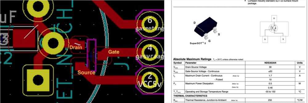 I looked at my already altered board ans saw a solution where I could turn the mosfet 90 degrees and only have to add a little more coppertape to connect it. finally it worked!
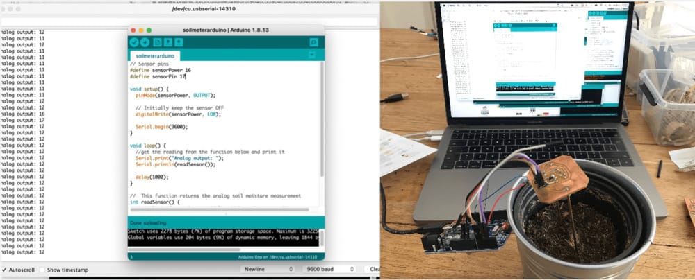
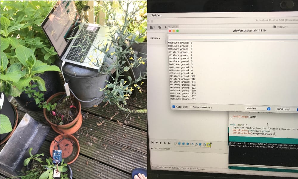
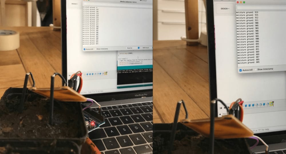
Of course I also had to test the soilmoisture-meter also, so I hooked it up to my computer to measure very dry soil and nicely wet soil. code moisture sensor
 1// Sensor pins
 2#define sensorgrondPower 14 // 11
 3#define sensorgrondPin  15 // 9
 4
 5void setup() {
 6// moisture
 7pinMode(sensorgrondPower, OUTPUT);
 8
 9  // Initially keep the sensor OFF
10  digitalWrite(sensorgrondPower, LOW);
11
12  Serial.begin(9600);
13}
14
15void loop() {
16  //get the reading from the function below and print it
17  Serial.print("moisture ground: ");
18  Serial.println(readgrondSensor());
19
20  delay(1000);
21}
22
23//  This function returns the analog soil moisture measurement
24int readgrondSensor() {
25  digitalWrite(sensorgrondPower, HIGH);  // Turn the sensor ON
26  delay(100);              // Allow power to settle
27  int val = analogRead(sensorgrondPin);  // Read the analog value form sensor
28  digitalWrite(sensorgrondPower, LOW);   // Turn the sensor OFF
29  return val;             // Return analog moisture value
30}
with the nicely wet ground I measured around 850
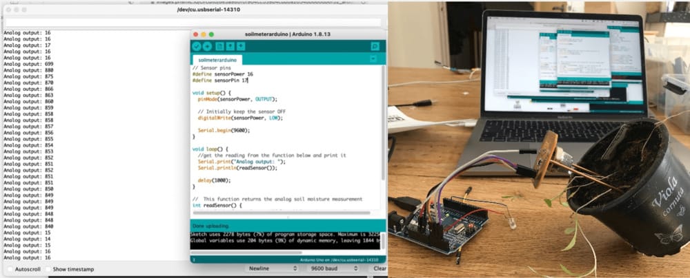 and with teh really dry soil I measured between 10 and 20
on sunday I tested both sensors at the same time, just to see if the code was working:
 1// gas
 2int luchtValue;
 3int digitalluchtValue;
 4// moisture
 5#define sensorgrondPower 11
 6#define sensorgrondPin 9
 7
 8
 9void setup()
10{
11Serial.begin(9600); // sets the serial port to 9600
12// gas
13pinMode(10, OUTPUT); //gasvraag
14pinMode(5, OUTPUT); //wormgeel
15pinMode( 3, INPUT);
16// moisture
17pinMode(sensorgrondPower, OUTPUT);
18
19// Initially keep the sensor OFF
20digitalWrite(sensorgrondPower, LOW);
21}
22
23
24void loop(){
25//gassensor heater aan
26digitalWrite(10, HIGH);
27
28//get the reading from the moisturefunction below and print it
29  Serial.print("moisture ground: ");
30  Serial.println(readgrondSensor());
31  delay(200);
32
33 // gassensor
34
35delay(3000);
36luchtValue = analogRead(8); // read analog input pin 0 gasmeet
37digitalWrite(15, LOW);
38
39if(luchtValue>400)
40{
41digitalWrite(13, HIGH);
42}
43else
44digitalWrite(13, LOW);
45Serial.print("air quality: ");
46Serial.println(luchtValue, DEC); // prints the value read
47
48delay(200); // wait 100ms for next reading
49
50}
51//  This function returns the analog soil moisture measurement
52int readgrondSensor() {
53  digitalWrite(sensorgrondPower, HIGH);  // Turn the sensor ON
54  delay(10);              // Allow power to settle
55  int val = analogRead(sensorgrondPin);  // Read the analog value form sensor
56  digitalWrite(sensorgrondPower, LOW);   // Turn the sensor OFF
57  return val;             // Return analog moisture value
58}
Monday Waagtime
All of a sudden nothing worked anymore and I got really frustrated, so I decided to go to Waag and be able to do something.
Housing
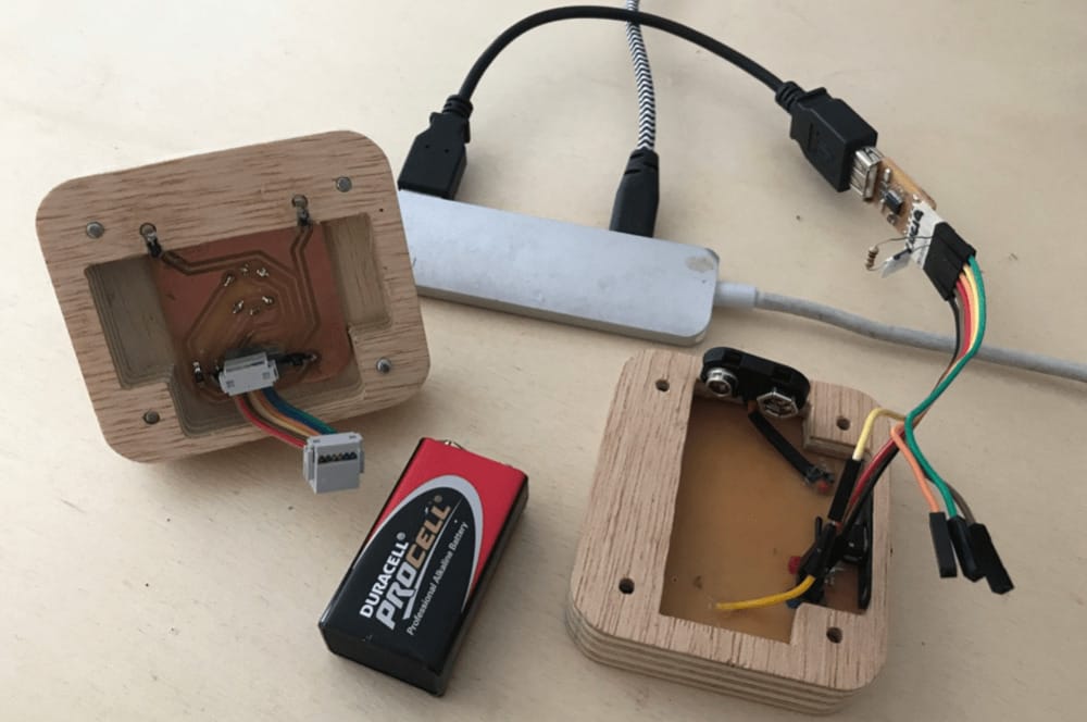
Hopefully I could work on the shopbot, but now Paula's wood had arrived, so she was shopbotting away all day. Loes gave me this great Idea to make the housing in the laser-cutter, there are many leftover parts of this 3mm board and that cuts easy with the lasercutter. I really had the plan to make my housing from this thick wood, but with the lasercutter I could make a great prototype and try and fit everything together. That way I could also see where I needed to alter my design for the cnc-milling later on. I made this great set with wooden layers and with that I could easyly fit all the parts together and measure everything, so later on all the loose parts (like the battery and the connector-wire) would have enough space.
Sensor-board
I looked with Henk to the board and reconnected everything and by miracle it worked. I think maybe the ground was not connected well enough before. all the connections on my board were disconnected, because the copper-layer would loosen. So in the second board I have to redesign it so that it won't breakk as easy. With this I also fund that the connecting-pins on the sensorboard have to be moved to the side for the battery and out of the center so it can fit next to the main-board-pins in the space in the product.
Tuesday Waagtime
Today was only a short time at waag, so I was a bit in a hurry. I got the board milled and got teh right connector-pins, so I could solder at night at home.
the holes in the sensor-board where too small again and I tryed to make them bigger, but by doing that all the copper-layers around the pins came loose again.
I will have to make a new one.
Wednesday at waag
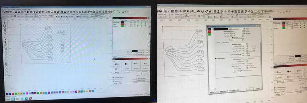
all the other students have their final presentation today, but therefor the shopbot is free again. I finished my design in illustrator (illustrator, since is is a 2-1/2-D) design, with outlines, pockets and drilling-holes.
V-carve would not work with my eps or svg files, because it thought that it were double lines. I could not take them out in illustrator (I tried by making the line-thickness smaller) and and I could not take out the double lines in v-carve, because it would see it as one shape.
Michelle and I tried all kind of different ways of importing my drawing in v-carve. DXF would not work. I decided to export my illustrator file to fusion and there turn it into a working dxf. but meanwhile Michelle found that you can import an Illustrator file (.ai) into v-carve and finally that solved the problem.
I inserted an 3mm milling-bit and milled away.
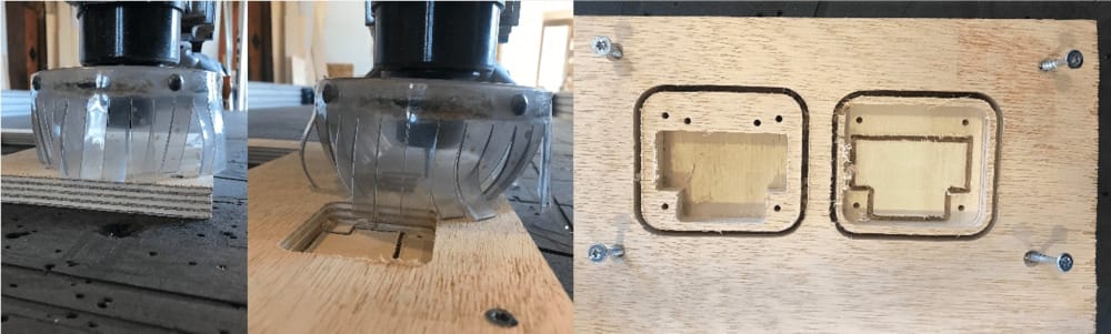 My plan to make the 1 mm holes for the gas-sensor I had to skip, because the final presentations were starting. and I changed the 2mm holes for my moisture-sensor-pins into 3 mm-holes, because the 2mm millingbit was not able to drill deep enough. I'll solve this by altering the fixing of the pins.
we had a good party for all the peaople that finished and on thursday waag would be closed. on friday I was not able to come to amsterdam and on monday was my final presentation so I have to work out everything at home. At the end of the afternoon Looes helped me to do some order-picking for the last electronic components and some bolts and nuts so I could fit everything together.
Thursday at home
soldering, sanding and finishing the wood for the housing
and slowly getting all the parts together.
Friday
Today my son is turning 11 and I had some appointments, so it was impossible to work a lot, but I managed to finish the soldering and I realised that I only thought of the button but never made a design and a plan.
this was awfull, because I really needed flexible filament to make the button move a little.
I saw that Loes was going back and forth to amsterdam and I asked her if she could pick up some filament in Amsterdam and we could do an axchange here at the trainstation in Haarlem. It turned out even better, she had the flexible filament at home and she could bring it on her way to Amsterdam. We made a great deal, I packaged a set of the filament that I have at home and she did the same for her filament and we both would have a better set of filament and would not have to buy any.
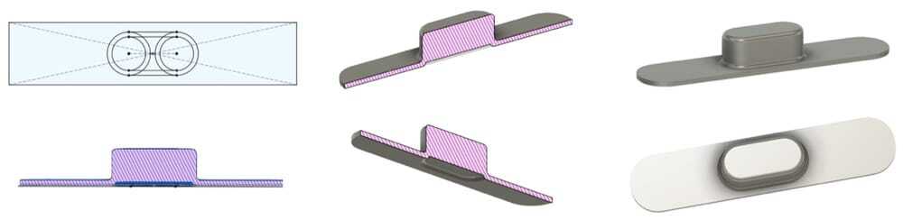 I made my design and made some prototypes in PLA so I could test the fitting around my button and then I made the real version in the flex-stuff. It worked great!
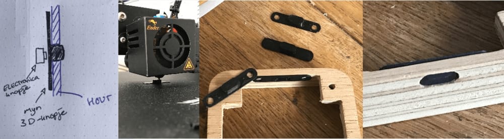 I was worried for a bit that I forgot to put the pulup-resistor with the button, but luckily the attiny has them build in and you can just put that in code:
I also looked into different ways of working with the button (for example push twice to wake up, long press for longer testing for example)
Now I had all the parts.
I tested the new moisture sensor:
 Measurements
very wet wormencompost 900
good wormcompost 700 tot 900
dry worm-compost under 700 gemeten: 681
That is really high, I can lower these measurements by making the conductive parts smaller.
Measurements
very wet wormencompost 900
good wormcompost 700 tot 900
dry worm-compost under 700 gemeten: 681
That is really high, I can lower these measurements by making the conductive parts smaller.
 hmm try a second time, with some tape around the copper-parts:
too dry 520
good 790-830
too wet 830-840n
hmm try a second time, with some tape around the copper-parts:
too dry 520
good 790-830
too wet 830-840n
Saturday
Stop motion video
I was inspired b y my first tries to make a stopmotion of the soldering and got (through a colleague) a better app to make the stopmotion. on saturdaymorning I made a nice setup on the dining-table to make the stopmotion and was happily playing for a few hours with all the parts to make a nice movie.
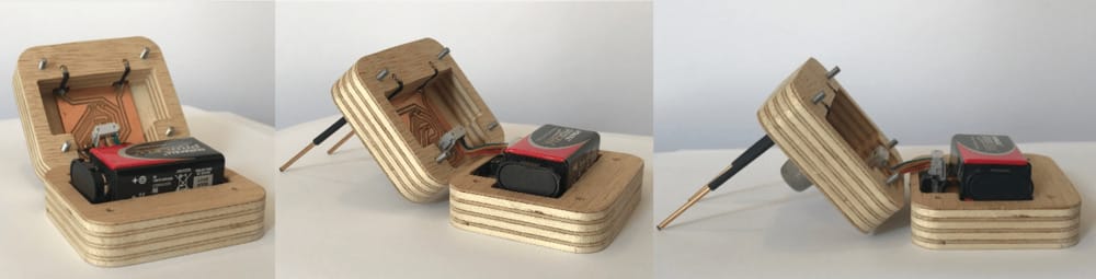
Assmebling the different parts:
After that I could finally assemble the parts for real. and make my definite video's of the product in action.
The code.
I connected all my code parts to one big code, with Erwins great 20 second explanaition on wednesday
1if ((something > amount) && (something < other amount))
2{ ..stuff happens..}
I had to add a lot of brackets....and it worked.
  1
  2// ledjes worm (lw)
  3#define lwgroenst 7
  4#define lwgroen 6
  5#define lwgeel 5
  6#define lworanje 4
  7#define lwrood 3
  8
  9
 10// ledjes grooundmoisture (lgm)
 11#define lgmrood 0
 12#define lgmgroen 13
 13#define lgmoranje 1
 14#define lgmtoprood 2
 15
 16// ledjed airquality (laq)
 17#define laqrood 16
 18#define laqoranje 14
 19#define laqgroen 15
 20
 21// sensors and switches
 22#define airon 10
 23#define groundon 11
 24#define knop 12 //(knop interrupt
 25#define sensorground 8
 26#define sensorair 9
 27
 28//variabelen
 29
 30int groundValue; // variabele moisturemeting tussen de 0 en 1024
 31int airValue; // variabele gasmeting tussen de 0 en 1024
 32
 33void setup() {
 34  // put your setup code here, to run once:
 35  // hier eerst de digital pinnen voor de LEDjes
 36pinMode(lwgroenst,OUTPUT);
 37pinMode(lwgroen,OUTPUT);
 38pinMode(lwgeel,OUTPUT);
 39pinMode(lworanje,OUTPUT);
 40pinMode(lwrood,OUTPUT);
 41pinMode(lgmrood,OUTPUT);
 42pinMode(lgmgroen,OUTPUT);
 43pinMode(lgmoranje,OUTPUT);
 44pinMode(lgmtoprood,OUTPUT);
 45pinMode(laqrood,OUTPUT);
 46pinMode(laqoranje,OUTPUT);
 47pinMode(laqgroen,OUTPUT);
 48
 49// the pins for turning on the sensors
 50pinMode (airon, OUTPUT);
 51pinMode (groundon, OUTPUT);
 52
 53// the pins for the sensors
 54pinMode (knop, INPUT_PULLUP);
 55pinMode (sensorground, INPUT);
 56pinMode (sensorair, INPUT);
 57
 58}
 59
 60void loop() {
 61// alles uit:
 62digitalWrite(airon, LOW);
 63digitalWrite(groundon, LOW);
 64
 65
 66  // als de knop ingdrukt wordt
 67   if (digitalRead(knop) ==LOW){
 68
 69// sensoren aan:
 70digitalWrite(airon, HIGH);
 71digitalWrite(groundon, HIGH);
 72
 73// herhaal loop 5 keer
 74for (int i = 0; i < 2; i++){
 75  //measure-loop wormen van groen naar rood en terug
 76   digitalWrite(lwgroenst,HIGH);
 77   delay(500);
 78   digitalWrite(lwgroenst,LOW);
 79   digitalWrite(lwgroen,HIGH);
 80   delay(500);
 81   digitalWrite(lwgroen,LOW);
 82   digitalWrite(lwgeel,HIGH);
 83   delay(500);
 84   digitalWrite(lwgeel,LOW);
 85   digitalWrite(lworanje,HIGH);
 86   delay(500);
 87   digitalWrite(lworanje,LOW);
 88   digitalWrite(lwrood,HIGH);
 89   delay(500);
 90   digitalWrite(lwrood,LOW);
 91   digitalWrite(lworanje,HIGH);
 92   delay(500);
 93   digitalWrite(lworanje,LOW);
 94   digitalWrite(lwgeel,HIGH);
 95   delay(500);
 96   digitalWrite(lwgeel,LOW);
 97   digitalWrite(lwgroen,HIGH);
 98   delay(500);
 99   digitalWrite(lwgroen,LOW);
100}
101   digitalWrite(lwgroenst,HIGH);
102   delay(500);
103   digitalWrite(lwgroenst,LOW);
104
105// de metingen:
106groundValue = analogRead(sensorground); // read analog input pin moisturemeting
107airValue = analogRead(sensorair); // read analog input pin gasmeting
108
109delay(200);
110// zet de sensoren weer uit:
111digitalWrite(airon,LOW);
112digitalWrite(groundon,LOW);
113
114
115/* start comment
116
117//grondrood en dan grondgroen via oranje naar rood en dan groen
118   digitalWrite(lgmgroen,LOW);
119   digitalWrite(lgmrood,HIGH);
120   delay(500);
121   digitalWrite(lgmrood,LOW);
122   delay(100);
123   digitalWrite(lgmgroen,HIGH);
124   delay(500);
125   digitalWrite(lgmgroen,LOW);
126   delay(100);
127   digitalWrite(lgmoranje,HIGH);
128   delay(500);
129   digitalWrite(lgmoranje,LOW);
130   delay(100);
131      digitalWrite(lgmoranje,HIGH);
132      digitalWrite(lgmtoprood,HIGH);
133      delay(500);
134      digitalWrite(lgmoranje,LOW);
135      digitalWrite(lgmtoprood,LOW);
136   delay(100);
137   digitalWrite(lgmtoprood,HIGH);
138   delay(500);
139   digitalWrite(lgmtoprood,LOW);
140   delay(100);
141   delay(100);
142   digitalWrite(lgmoranje,HIGH);
143   delay(500);
144   digitalWrite(lgmoranje,LOW);
145        digitalWrite(lgmgroen,HIGH);
146
147/// airquality eerst rood, groen, oranje ...groen...
148
149        digitalWrite(laqgroen,LOW);
150   delay(100);
151   digitalWrite(laqoranje,HIGH);
152   delay(500);
153   digitalWrite(laqoranje,LOW);
154   delay(100);
155   digitalWrite(laqrood,HIGH);
156   delay(500);
157   digitalWrite(laqrood,LOW);
158   delay(100);
159   digitalWrite(laqoranje,HIGH);
160   delay(500);
161   digitalWrite(laqoranje,LOW);
162   delay(100);
163        digitalWrite(laqgroen,HIGH);
164
165end comment */
166
167// knalgroene worm Alles tiptop
168if ((airValue <=150) && (groundValue > 700) && (groundValue <= 850))
169{ digitalWrite(lwgroenst,HIGH);
170  digitalWrite(laqgroen,HIGH);
171  digitalWrite(lgmgroen,HIGH);
172
173  delay(5000);
174  digitalWrite(lwgroenst,LOW);
175  digitalWrite(lgmgroen,LOW);
176  digitalWrite(laqgroen,LOW);
177}
178
179// voorbeeld: else if ( (10 < i) && (i <= 20) )
180
181 // lekker groeneworm (beetje vochtig, verder goed)
182else if ( (airValue <=150) && (groundValue > 850) && (groundValue <= 900)) {
183
184   digitalWrite(lwgroen,HIGH);
185   digitalWrite(lgmoranje,HIGH);
186   digitalWrite(laqgroen,HIGH);
187     delay(5000);
188   digitalWrite(lgmoranje,LOW);
189   digitalWrite(lwgroen,LOW);
190   digitalWrite(laqgroen,LOW);
191}
192
193// lekker groeneworm, beetje droog, prima lucht
194else if ((airValue <=150) && (groundValue <= 700)) {
195   digitalWrite(lwgroen,HIGH);
196   digitalWrite(lgmrood,HIGH);
197   digitalWrite(laqgroen,HIGH);
198     delay(5000);
199   digitalWrite(lwgroen,LOW);
200   digitalWrite(lgmrood,LOW);
201   digitalWrite(laqgroen,LOW);
202}
203
204// gele worm, beetje vochtig, beetje foute lucht
205else if ((airValue > 150) && (airValue <=300) && (groundValue > 850) && (groundValue <= 900)) {
206   digitalWrite(lwgeel,HIGH);
207   digitalWrite(lgmoranje,HIGH);
208   digitalWrite(laqoranje,HIGH);
209     delay(5000);
210   digitalWrite(lwgeel,LOW);
211   digitalWrite(lgmoranje,LOW);
212   digitalWrite(laqoranje,LOW);
213}
214
215// gele worm, te droog, beetje foute lucht
216else if ((airValue > 150) && (airValue <=300) && (groundValue <= 700)) {
217   digitalWrite(lwgeel,HIGH);
218   digitalWrite(lgmrood,HIGH);
219   digitalWrite(laqoranje,HIGH);
220     delay(5000);
221   digitalWrite(lwgeel,LOW);
222   digitalWrite(lgmrood,LOW);
223   digitalWrite(laqoranje,LOW);
224}
225
226// oranjeworm te nat, beetje foute lucht
227else if ((airValue > 150) && (airValue <=300) && (groundValue > 900)) {
228   digitalWrite(lworanje,HIGH);
229   digitalWrite(lgmtoprood,HIGH);
230   digitalWrite(laqoranje,HIGH);
231      delay(5000);
232   digitalWrite(lgmtoprood,LOW);
233   digitalWrite(laqoranje,LOW);
234   digitalWrite(lworanje,LOW);
235}
236
237// oranjeworm tedroog, foute lucht
238else if ((airValue >300) && (groundValue <= 700)) {
239   digitalWrite(lworanje,HIGH);
240   digitalWrite(lgmrood,HIGH);
241   digitalWrite(laqoranje,HIGH);
242      delay(5000);
243   digitalWrite(lgmrood,LOW);
244   digitalWrite(laqoranje,LOW);
245   digitalWrite(lworanje,LOW);
246}
247
248// helemaal mis, foute grond, foute lucht
249else if ((airValue > 300) && (groundValue > 900)) {
250   digitalWrite(lwrood,HIGH);
251   digitalWrite(lgmtoprood,HIGH);
252   digitalWrite(laqrood,HIGH);
253      delay(5000);
254   digitalWrite(lwrood,LOW);
255   digitalWrite(lgmtoprood,LOW);
256   digitalWrite(laqrood,LOW);
257}
258
259// extra stukjes die ik gemist had:
260
261//  oranjeworm zeiknat, prima lucht
262else if ((airValue <=150) && (groundValue >900)) {
263   digitalWrite(lworanje,HIGH);
264   digitalWrite(lgmrood,HIGH);
265   digitalWrite(laqgroen,HIGH);
266     delay(5000);
267   digitalWrite(lworanje,LOW);
268   digitalWrite(lgmrood,LOW);
269   digitalWrite(laqgroen,LOW);
270}
271
272// geleworm goeiegrond, beetje foute lucht
273else if ((airValue > 150) && (airValue <=300) && (groundValue > 700) && (groundValue <= 850)) {
274   digitalWrite(lwgeel,HIGH);
275   digitalWrite(lgmgroen,HIGH);
276   digitalWrite(laqoranje,HIGH);
277      delay(5000);
278   digitalWrite(lgmgroen,LOW);
279   digitalWrite(laqoranje,LOW);
280   digitalWrite(lwgeel,LOW);
281}
282
283//rode worm, lucht is afschuwelijk grond is prima
284else if ((airValue > 300) && (groundValue > 700) && (groundValue <= 850)) {
285   digitalWrite(lwrood,HIGH);
286   digitalWrite(lgmgroen,HIGH);
287   digitalWrite(laqrood,HIGH);
288      delay(5000);
289   digitalWrite(lwrood,LOW);
290   digitalWrite(lgmgroen,LOW);
291   digitalWrite(laqrood,LOW);
292}
293//rode worm, lucht is afschuwelijk grond beetje nat
294else if ((airValue > 300) && (groundValue > 850) && (groundValue <= 900)) {
295   digitalWrite(lwrood,HIGH);
296   digitalWrite(lgmoranje,HIGH);
297   digitalWrite(laqrood,HIGH);
298      delay(5000);
299   digitalWrite(lwrood,LOW);
300   digitalWrite(lgmoranje,LOW);
301   digitalWrite(laqrood,LOW);
302}
303
304
305
306// eindstukje:
307
308      //snelle loop wormen van groen naar rood en terug met drie keer blinken aan het einde
309   digitalWrite(lwgroenst,HIGH);
310   delay(200);
311   digitalWrite(lwgroenst,LOW);
312   digitalWrite(lwgroen,HIGH);
313   delay(200);
314   digitalWrite(lwgroen,LOW);
315   digitalWrite(lwgeel,HIGH);
316   delay(200);
317   digitalWrite(lwgeel,LOW);
318   digitalWrite(lworanje,HIGH);
319   delay(200);
320   digitalWrite(lworanje,LOW);
321   digitalWrite(lwrood,HIGH);
322   delay(200);
323   digitalWrite(lwrood,LOW);
324   digitalWrite(lworanje,HIGH);
325   delay(200);
326   digitalWrite(lworanje,LOW);
327   digitalWrite(lwgeel,HIGH);
328   delay(200);
329   digitalWrite(lwgeel,LOW);
330   digitalWrite(lwgroen,HIGH);
331   delay(200);
332   digitalWrite(lwgroen,LOW);
333   digitalWrite(lwgroenst,HIGH);
334   delay(200);
335   digitalWrite(lwgroenst,LOW);
336   delay(100);
337   digitalWrite(lwgroenst,HIGH);
338   delay(200);
339   digitalWrite(lwgroenst,LOW);
340   delay(100);
341   digitalWrite(lwgroenst,HIGH);
342   delay(200);
343   digitalWrite(lwgroenst,LOW);
344   } // einde knop
345}
I made this great yellow wire connected to the updi-pin so I can really do some embedded coding. Here is the setup for uploading my code. I just disconnect my sensro-board and connect the ground, vcc to the connectorpins and hook up the yellow updi-cable to the updi.
 Only thing I do not really like is that the tx and rx-pins are in use for my LED's so with the first board I did some readings and with the second board I wanted to make a via and just as the updi-pin connect a wire on the back. But with all the hurrying and stress of other people wanting to mill ass well I did not make that. That will be the next spriral.
Sunday
Getting the video and presentation ready. I worked all day in I-movie to make the video and had to make extra shots of me on the balcony, the worms and my design-booklet. I was really good fun to think about the video and try and fit everything into 1 minute. At night the video was ready and I tried to make it under 10 mb, but that was almost impossible. After working out the special tricks in handbrake I finally found the RF quality slider and by changing that to a higher number I lowered the quality and got the video under 10MB.
Now I uploaded it to my static-folder, so it would be online in my main folder.
pffffffff, finally time to sleep.
Monday
I made my presentation slide, I realised that I did not make any pictures of the sensor-side of my product, so I had to build my mini-studio-again. and with that I had all the information to make the slide.
 In the afternoon I went to amsterdam and after all these other presentations it was my turn. It went great, everybody liked the stop-motion (I really liked that, because I put a lot of effort in that ;-)) and Neil suggested that I could make the future product more environment-proof. that was already another spiral so gave a good conversation.
After that champagne in the Waag and beers on the square!
Learnings this project
I really liked making something that you can really hold in your hands and does something, giving the interaction that I want. Meantime I underestimated the time it would take to finish this small and quite simple product, with only two sensors and LED-output.
- I loved thinking out the design, so it would be nice and small and well integrated.
- I got a bit nervous with the timing that I was still working out my sketches and everything and I saw all these colleague-students making things already.
- It is not a good idea to have a cornea-infection in the last week before the finish, I could hardly see anything for 5 days, luckily Henk postponed my presentation and I did have time to finish it with high quality.
- It is really nice to have an industrial design back-ground, because I could really use a lot of those competentions in this project. I loved it that I could decide that I would first focus on the technical part and after that, according Bauhaus's:'form-follows-function' work on the system integration.
- It takes a lot ot time to make a beautifull product, everything has to be fitting perfect and it really feels that all the work is precise.
- Making a stopmotion was really good fun, but also meant that I could not connect all the parts until it was finished. That was quite a challenge in the process of making the product.
- Making the video took me a whole day, it was nice work, but it really takes a lot of time. I think my choice of using I-movie was fine, but maybe next time I would use premiere-pro again. not everything is possible in I-movie, i.a. there is no good way of making subtitles in I-movie.
- I trusted the kicad-library of the fab-lab, but that turned out to be not true. It took me days to change things around, and it really felt like a waste of time. It really would be nice if that library is checked by some poeple with knowledge of electronics.
- I only wrote the documentation on the final project while I worked, I really had a lot of work afterwards to make all the right pictures with it. I think that the hard deadline in combination with me wanting to do everything really beautiful did not help.
- I had good fun! and I am really happy with the end-result!
Links to Design-files
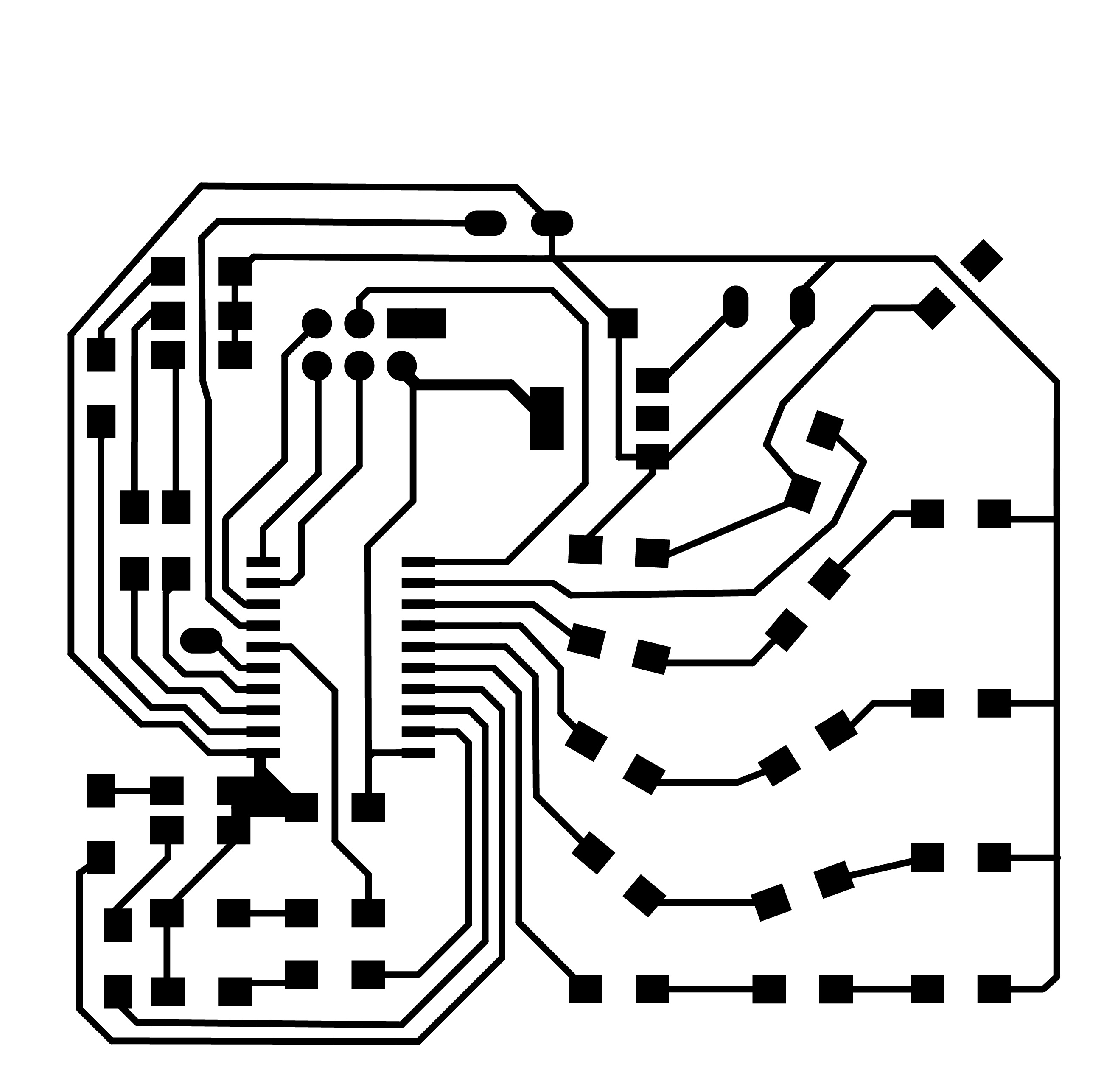
PNG-files Worm-mood-station-main-board:
- wms-traces.png or download
- wms-outline.png or download
- wms-tekst.png or download
- wms-gaten.png or download
KiCAD-archive Worm-mood-station-main-board:
Illustratorfile Worm-mood-station-main-board, with PCB and worm-vector-screen layers:
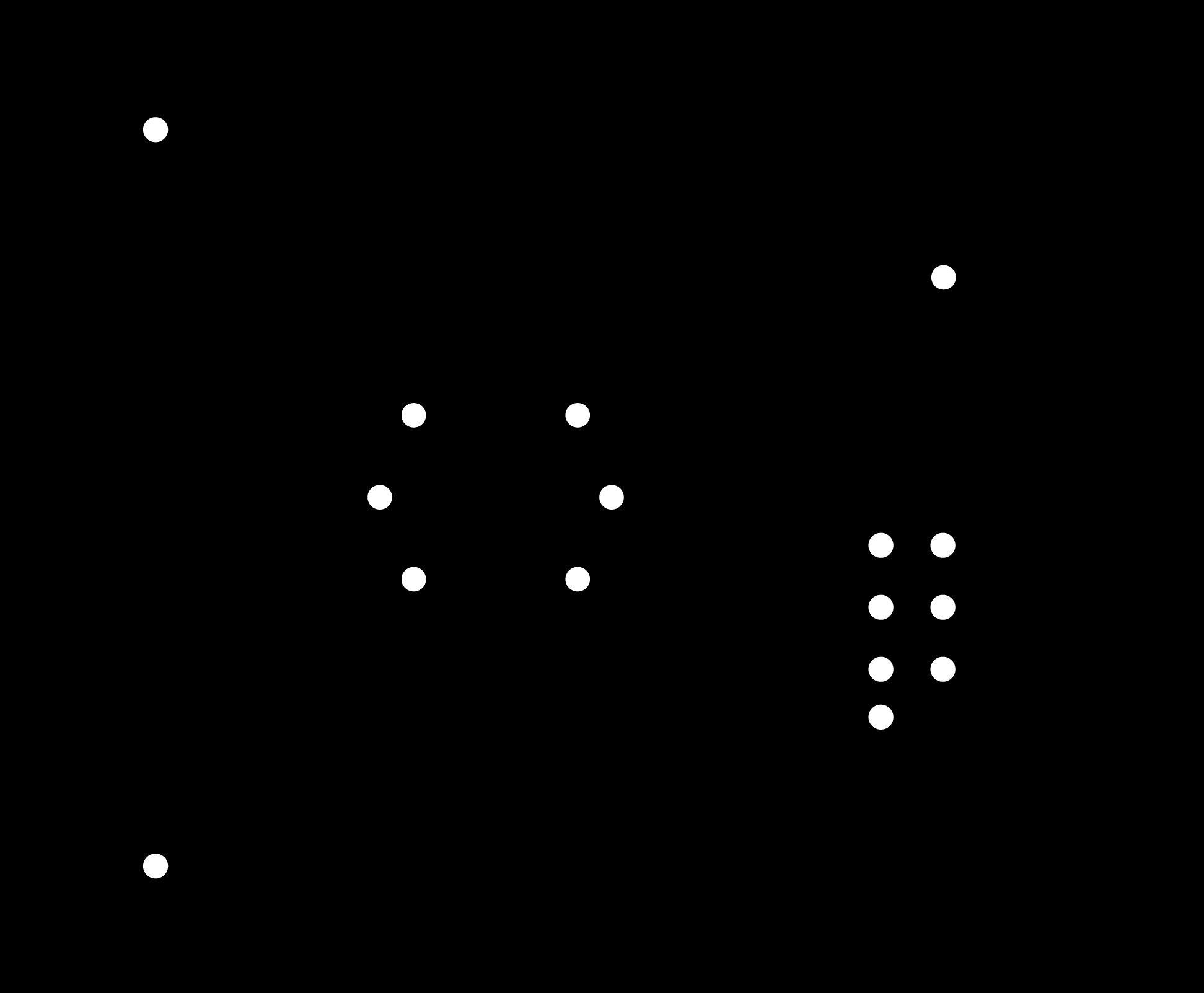
PNG-files Sensorboard:
- sensorworm-gaten.png or download
- sensorworm-outline.png or download
- sensorworm-traces.png or download
KiCAD-archive Sensorboard:
Illustratorfile Sensorboard:
Housing prototype, for on the lasercutter
Housing shopbotfile:
- wormhuisshopbot.eps or download Housing illistratorfile
- wormhuis.ai or download
Button dfx-file and stl-file