Make Something Big (aka Computer-Controlled Machining)
This is the only machine I am afraid of - henk
Description
This machine kills. The only machine that can kill you etc. etc. In other words: we are going to try to make something big this week. The week has a very weird combination of constraints. On the one side we have to work with a machine that is VERY DANGEROUS, on the other hand we are under a lot of time pressure. Interesting combination, no?
Assignments - Learning Outcomes
| # | Assignment | Fin |
|---|---|---|
| 1 | Demonstrate 2D design development for CNC production | 1 |
| 2 | Document your work (in a group or individually) | 0 |
| 3 | Make (design+mill+assemble) something big | 1 |
Spirals - Have you?
| Spirals | Description | Done |
|---|---|---|
| A | Linked to the group assignment page | 0 |
| B | Documented how you designed your object (something big) | 1 |
| C | Documented how you made your CAM-toolpath | 1 |
| D | Documented how you made something BIG (setting up the machine, using fixings, testing joints, adjusting feeds and speeds, depth of cut etc.) | 0 |
| E | Described problems and how you fixed them | 1 |
| F | Included your design files and ‘hero shot’ photos of final object | 1 |
Assignment: learn how to operate the shopbot
There are two main parts to understand the shopbot: safety and the actual operation. We spend a considerable amount of time on safety as this is a dangerous machine. Did I already mention it can kill you in several ways?
Safety, or how to survive the shopbot.
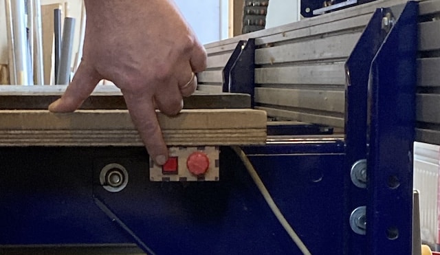
Before you can do anything safety related anywhere, you need to know where you are.
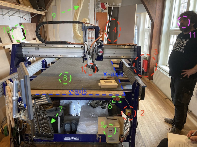
First the most important parts in red, then the green to operate the machine. Pink is optional.
- the actual tool; here is the drill.
- Emergency stop
- Fire extinguisher
- Dust collection
- set rotation speed of the mill (18k rpm)
- turn the ventilation on and adjust sucking power
- shopbot terminal (use spacebar to pause job)
- bed with sacrificial layer
- exhaust pipe for dust
- extra material
- Henk looking worried (for size reference)
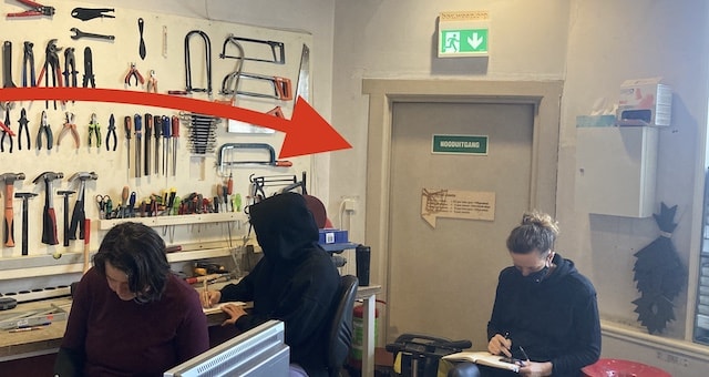
on the sother side of the room you find the emergency exit
Do not operate the shopbot when you:
- are alone in the building
- are stressed or distracted
- have loose stuff (hair, necklaces etc) hanging around
- are in doubt you followed the right steps.
- did not clear the entire machine of material
- see other people in the room not paying attention
- do not know where the emergency exit is
- do not know where the fire extinguisher is
- do not know where the emergency stop button is
- are not wearing protective gear (glasses)
- are not willing or able to rethink at least three times every step you need to take.
Only turn on the machine when:
- you are working on it
- when you need to work with the shopbot software
- checked that the mill is in the collet and the nut is tight securely by yourself
- the skirt is up and tight securely by yourself.
When the machine is operational and you are milling material
- watch the drill and watch out for sparks.
- if you see a spark, stop the machine and stop the ventilation
- walk to the dustcollection
- release the bag with dust and check for fire/sindering parts
- If you see anything even vaguely looking like fire; take the bag outside. (if there is a lot of fire, throw it out the window, if it is a little, take the CLOSED bag down the stair to the front door)
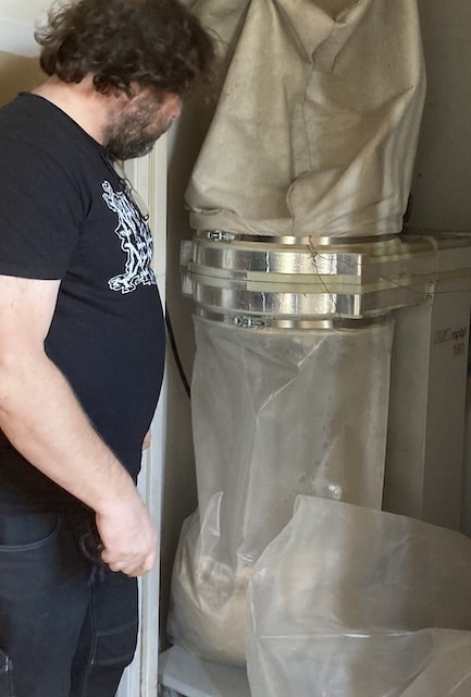
this is the bag that needs to go in case of smoldering sparks
About fire
Fire is the biggest danger for Waag. Not so much because of potential live loss, but because of the monumental status of the building.
Stuff that you have to look out for as they can cause a fire are:
- when the milling bits hit something iron: like a screw holding your stock to the plate.
- burning cinders that spark of your stock
- when the mill is in the wood spinning but not moving the material heats up fast
- when you pause your job; move your mill out of the stock!
Machine operation, or how to master the shopbot
The shopbot is a wonderfull machine that has brought CNC-ing capabilities within reach of <€100.000,- fablabs. It is basically a remake of the far more expensive CNC machines by Ted. You can see him in this video around the 40min. mark talking about the history of Shopbot.
It has dedicated gcode software for it. This software is only needed to steer the machine. The design and CAM-ing of your design is done in a program as Fusion360 or VCarve.
VCarve Software
In VCarve you set all the parameters that define speeds and feeds of the mill. Rotation, XYZ-movement, stepover, passes etc. etc. can all be set in Vcarve and exported as gcode to be used in the shopbot program. Note that the actual speed of the milling bit can not be set in VCarve. This is done by hand using the machine under the shopbot. See #5 in the drawing at the top of this page.
NOTE: all of what VCarve is used for, can also be done in Fusion360. For this assignment we need to understand VCarvePro, but in reality it would be handier to go from Fusion360 directly to shopbot and skip VCarve as the licensing model of VCarve does not allow for home usage.
Usage Create a new file or open an existing DXF.
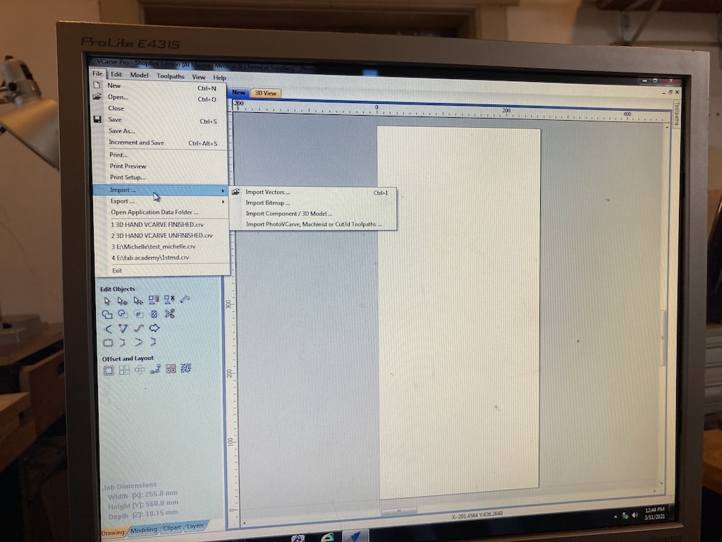
Use the job setup to define material size. Mind the x and y axis! The red dot in the overview defines the origin. It is handy to set the origin as close to you as possible.
When you have to define the Z, don't believe what the manufacturer of the material told you, but measure for yourself. If the material various in thickness across the board, you need to accept that only the average will be good enough.
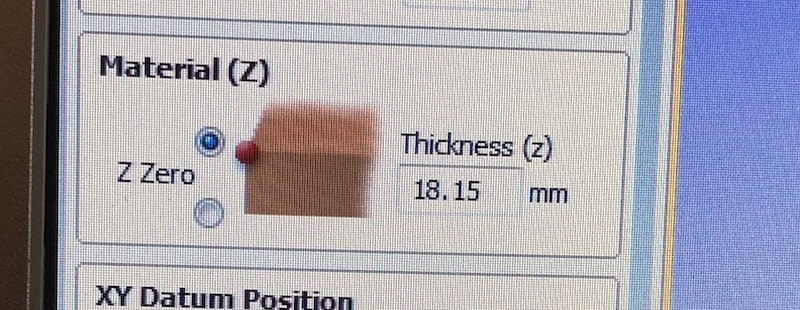
But better be conservative in your Z distance: it is easier for you to remove an extra 0.1mm of material by hand from your end-result then it is for Henk to put on a new sacrificial layer on the shopbot.
As you are milling, you have a horizontal movement that pushes your stock out of place. So you need to fixate it in one place. We do this by screwing the stock to the sacrificial layer. To make sure it is stuck in many places and secure, we pre-drill the hole using the shopbot. As the drilling of hole is a purely vertical operation, we do not risk the stock being pushed out of place.
Toolpaths Our main environment in Vcarve is the toolpath. Here you can select the operation you want to be performed, on which paths it should be performed and what the characteristics of that operation are.
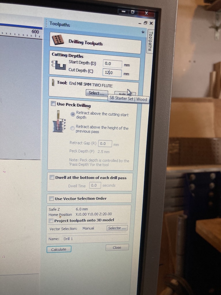
Per toolpath you can set the speeds and feeds. Feeds and speeds depend on the material you are using and the desired result. For this weeks assignment we used
- 5mm milling bit
- spindle speed of 14.000 rpm
- feed rate 80 mm/sec
- plunge rate 20mm/sec
Note again that the spindle speed is set in VCarve pro, but not operated by it. On the shopbot you set the spindle speed manually (see #5 in the picture above)
Shopbot software
In order to use the shopbot software, the machine needs to be on. The software interfaces directly with the machine and has no clue what to do when there is no machine on the other side of the line.
Here you can see the interface with its three most important features
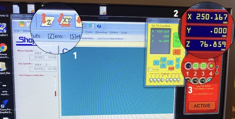
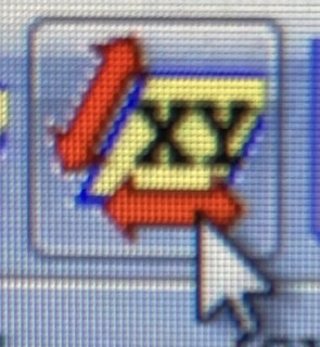
- various menu items and icons to set the x, y and z axis
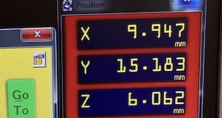
- the current position of the millbit (take a picture before zero-ing)
- closed-loop indication for the zero-ing of the Z-axis (more on that later
The machine itself
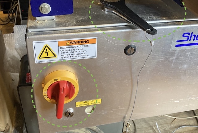
On the side of the shopbot, you find the main on switch and the tools to change the drilling bit. Notice how there is a little wire hanging from the tool: on the other side you find the key to turn on the milling-motor. This way you can't change the milling bit when it is still turning as this would cause YAWTSCKY.
EnderSandman, or how I made a box for my 3D printer.
tl;dr
- create all objects
- lay objects flat
- add dogbones
- project result on new sketch plane
- export this sketch to dxf
- define paths are profiles, holes and pockets in VCarve.
- export holes to one gcode file, and pockets and profiles to another gcode file.
- run the mill.
- profit
The longer story:
As my project for the Make Something Big week, I chose to make a house for my 3D printer and for the CNC.
Some of the amazing design features that my machine-home will include are:
- connection to a ventilation system that sucks away any airborn particles created by either machining operation.
- holes for power and other circuitry
- a see-through front that snap nicely into the home.
- a little protruding tab on the front of the machine home with a 3mm deep pocket to temporarily store milling bits, SD-cards and other little utensils.
- a hole in the top of the 3D printer box to guide filament from outside the home into the box.
- a kick space under the box that leaves room for future drawers in which I can save all tools needed for machine operation.
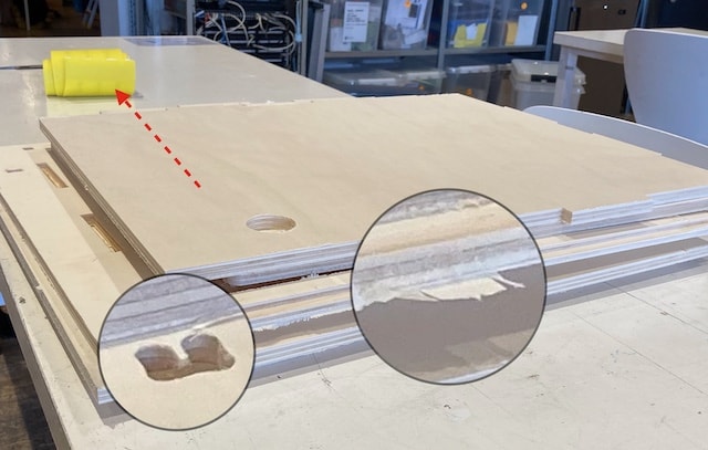
Sadly I had to adjust my aspirations as the stock material was not enough for all that I wanted to make.
(here you can see I already part of the planes on the stock. And there is no more place left for all the other materials...)
I made my model in Fusion360 using a Youtube tutorial. The tutorial also stipulates how you can create a gcode file directly in Fusion360. This would allow me to by-pass the closed source windows software VCarve. But it would also bereft me of the oppertunity to do things Waag Fablab way.
For inspiration and guidance I basically followed all the steps in formentioned video.
- Create sketch with through cut of all parts.
- use extrude and mirror to create all parts
- add tabs to the different planes to extend them into other planes
- use these tabs as cut tools to make pockets and profiles in planes
Where I diverted from the video was:
- I added a bunch of fillets to make corners more rounded and pleasing
- I added a front plane (not normal in a bookshelve) and created a profile in that front pane so that a acrylic window can be added at a later stage.
- The bottom shelve is extended outside the box and has a pocket. This feature can serve as a little workbench to temporarily store stuff
- the kick is (much) deeper then in the original video. I want to make some small drawers underneath to store machine related tools.
- the top contains a little hole for 3D filament to pass through
- the back contains an extra hole for power to the 3D printer
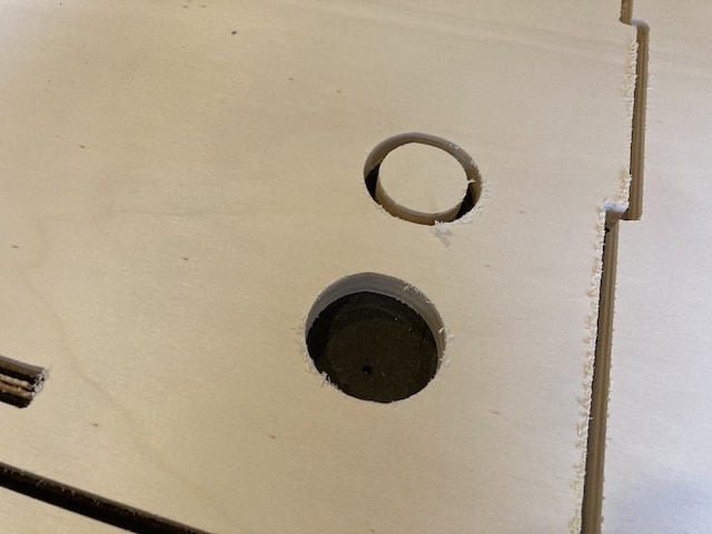
- the right side contains 2 holes. These are for future connection to the CNC home. It is for ventilation purposes and allows extraction of fumes into the ventilation system.
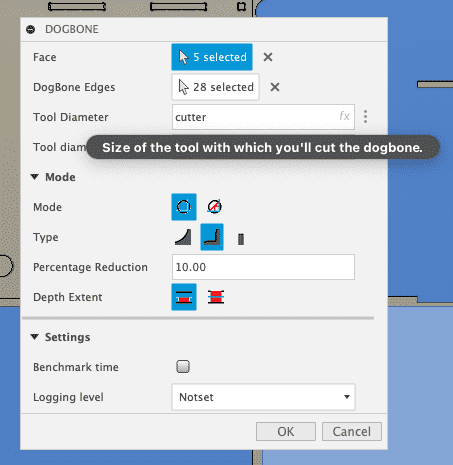
Extra pro-tip: there is a little Ad-in called Dogbone. This add-in takes cares of creating all the dogbones to your hearts desire. Just select the planes of the parts you need to have dogboned, press the right buttons and see an error...
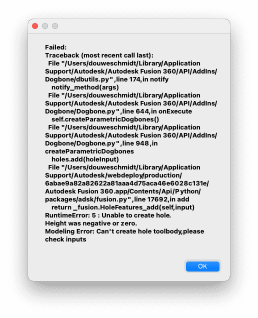
Fiddling around with different presets did bring good result in the end. Just a plain old case of trial and error.
It is really nice that you can already define the size of your tool here.
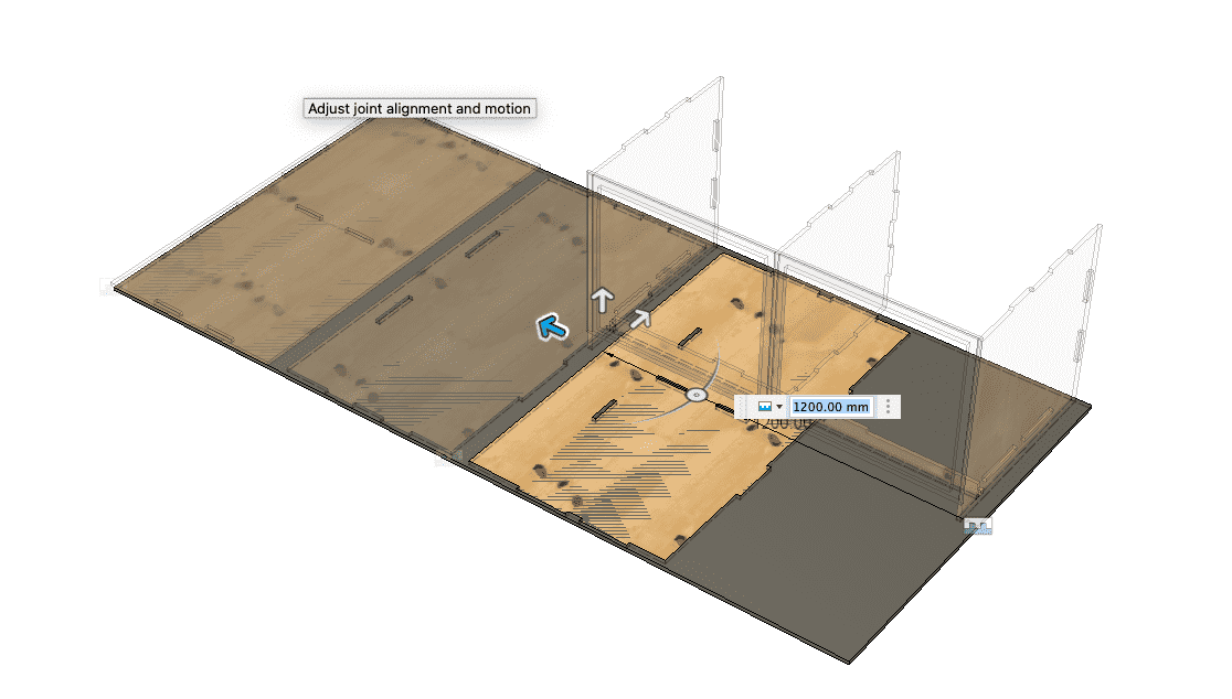
Also I used the brand new nesting service from Fusion360, instead of using the joint feature that was used in the video.
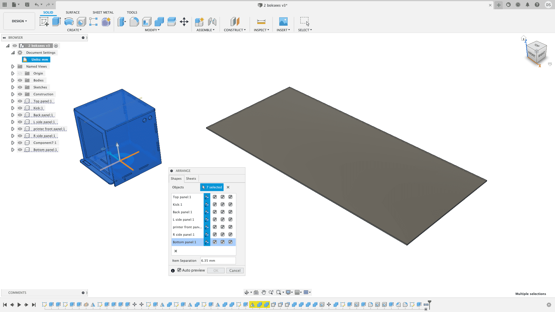
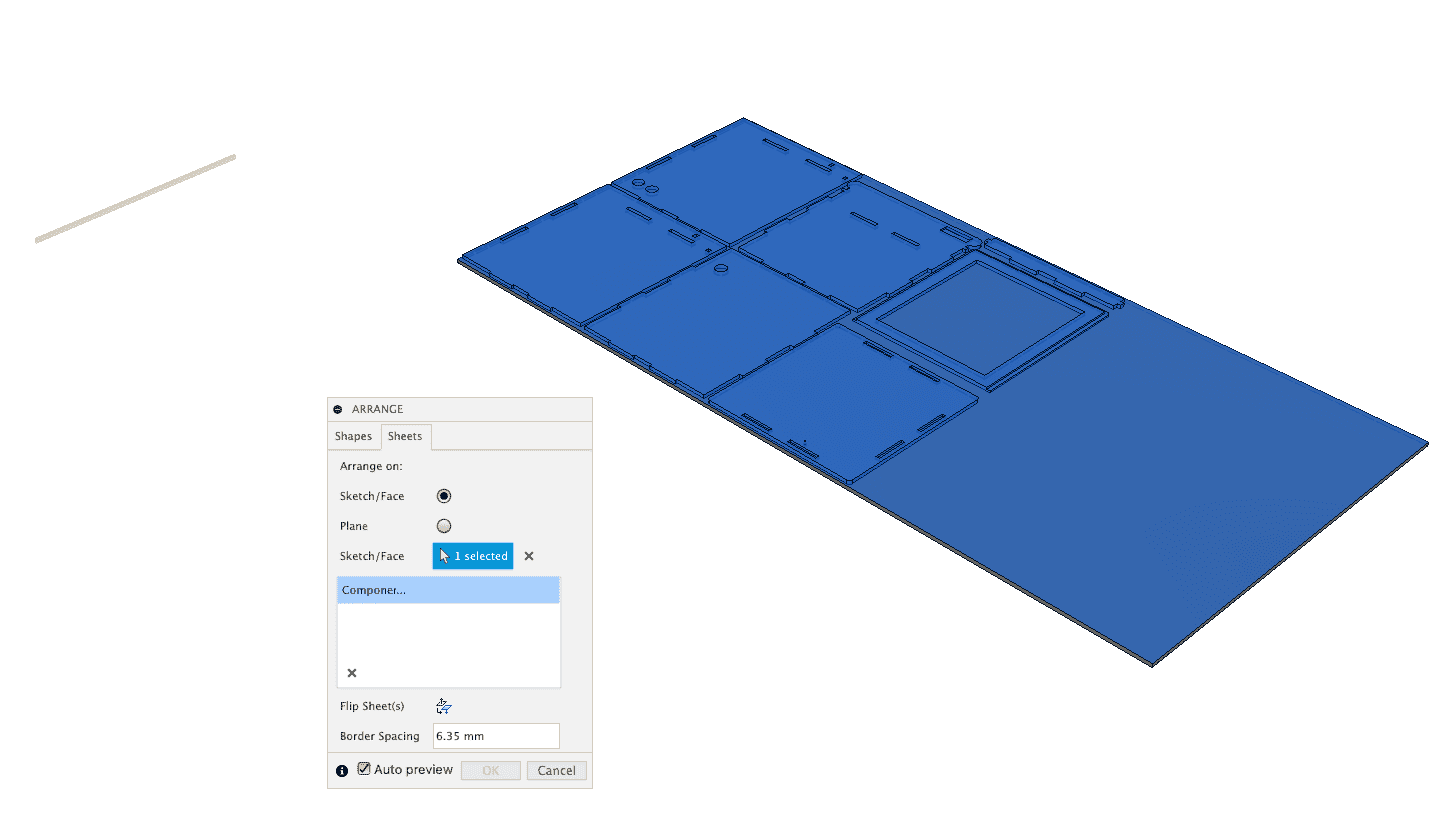
The result is a plane with all parts next to each other. These parts were projected onto a new sketch-plane. This new sketchplane was exported to DXF. This file now awaits further processing by the VCarve software.
Things to look out for tomorrow:
- There is a slope on one side of the pocket the front of the bottom plane: will this print well?
- the dogbones are shallow; do I get away with this? I made them shallow as I do not want the air to move out and prevent sound leakage.
- Will I be sharp enough to create all the correct path and export them to the right files for gcode/shopbot use?
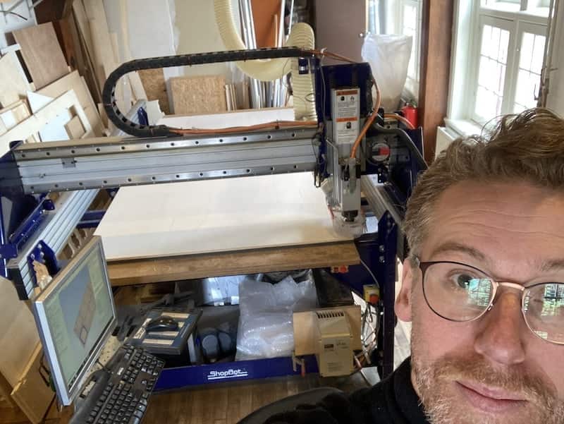
Milling day has come!
I was up and early at Waag. I was ready. The shopbot was ready. It just needed some sanding and vacuuming to make sure that the bed was perfectly flat. I set myself behind the terminal, inserted the thumbdrive with my .dxf file on it and loaded it in VCarve.
In VCarve I followed the steps as outlined above: first step is to set material dimensions (1220 to 2500 in this case).
Also I drew a bunch of circles around the profiles. These are the places where the woodies can be drilled through the plate into the sacrificial layer and keep the stock in place during the milling process.
I had to define several different milling actions.
- The woodies. These are drill operations that go halfway down the stock to leave some material for the woodies to grab onto.
- the pocket for the 'penholder' I made.
- the pockets of the blind tabs.
- the pocket cutout that creates the front frame. A profile cut makes sure it fits as a door and a pocket cut that holds the acrylic window.
- the profile cuts that hold tabs and a profile cut to make sure you can see through the front panel.
- and finally the profile cutout of all the plane profiles
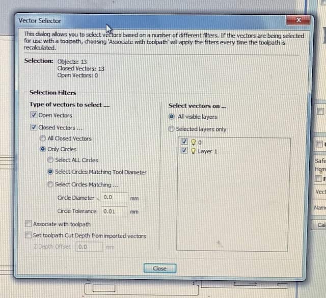
You can select all the paths by hand and this is probably the best way to do it as it makes you think again about what you are doing.
But, there is also a handy selection tool that you can use to select several paths that share a common feature at once. For example; all paths that are exactly the diameter of the tools (ie. all the woody-holes).
Keeping tabs on your tabs
Special not needs to be made of the tab creation. Tab serve to hold profile cutouts in their place. Especially small parts that are cutout entirely can be grabbed by the milling bit and flung accross the room if they are not secured with a tab causing a YAWTSCKY (Yet Another Way The Shopbot Can Kill You).
The ideal Tab for our jobs is 5x5mm. The smaller pieces can do with one tab, but for the bigger profiles a tab on each side is advisable.
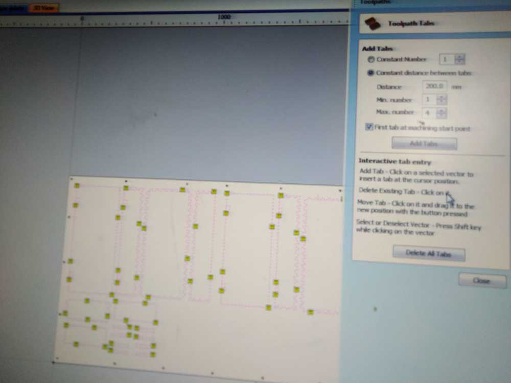
Tabs in Vcarve (image by Tessel)
Dodging the dogbones
The mill, being round can’t mill sharp corners in the inner pockets. Therefore you add dogbones. These are little rounds that allow the mill to get in all the way. Dog bones are 50% of the diameter of the end mill. So 2.5 mm dog bone for the 5mm drill. If you do not add them your model will not be press fit.
You can add these dogbones in Vcarve. in my case this was not necessary as I already added them in Fusion360 using the plugin.
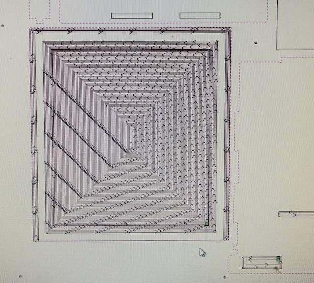
After you’ve added tabs, dog bones etc. you calculate the toolpaths. You can access this feature through the toolpath menu. You can choose to show one toolpath or all. Reset preview will remove all toolpaths from the model so you can start a new preview.
Preview
And then you are left with a great preview of your final cut. You can even watch a little movie that shows you what will happen when you start milling. This is a great feature to spot any weird things or parts you might have missed. I didn't see any and called Henk to come and check my design.
One odd thing
There was only one small issue:
The front pane of my machine home is a window. It will hold a piece of acrylic in a carefully removed profile on the inside. This pocket is only 40mm wide and stops where the actual window starts: a profile operation has been made for this complete cutout. But the pocket function did not stop at the edge of the profile cut.
This does aid very functional wood trash removal as almost a complete pane will be made into sawdust and transported into the dustcollector. But it will also use up a lot of my machine time and unnecessary consume power, wear out the milling bit and create noise as a silly byproduct.
Henk showed me how you can select two paths an indicate in Vcarve that you only want the part in between milled. That solved that.
Exporting
When you save your paths you can indicate which paths you want to save to a file. We need two files: one for the woodies, and one for the rest. You selected the paths that you want to export in the saving window and indicate a nice memorable location for your shopbot file.
Prepping the Machine.
- Put the big wooden multiplex plate on the shopbots sacrificial layer.
- Remove the milling bit from the machine.
- inspect the milling bit and make sure that
- it is not damaged
- it is the right bit
- it sits deep enough in the collet.
- reinsert the milling bit in the router
- tighten the router with just enough strength that you know you can also still loosen it later.
You can now turn on the machine with the big red knob on the side. Otherwise the shopbot program does not work.
After you open the shopbot program, you are no longer allowed to use any other program on the shopbot terminal. There is a direct serial link to the shopbot operations. Fiddling around in the terminal might distort the shopbot creating YAWTSCKY.
- home the machine using the shopbot program
- set y and x to your preferred origin. (here I made the mistake of placing the origin approximately 1cm to far into y and x)
- make a picture of your current x and y.
- set this as your desired origin in the menu of the shopbot program.
- manually move the mill a bunch of centimeters over the stock to zero the Z. (don't do this at the corners as corners tend to be somewhat higher)
- put the aligator clip under the mill
- check for conductivity by tapping softly with the aligator clip against the mill
- these dots should light up, indicating a short circuit has been established.

- after that you can press the Z button in shopbot.
- You need to confirm one more time that things are going well on your side of the screen.
- Hear the siren wailing as the mill moves down towards the aligator clip. If all is fine, it should stop as soon as a short is created.
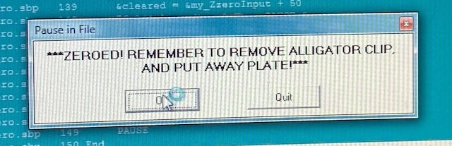
- manually higher the mill and remove the aligator.
- You are now ready to drill the woody holes!
Running the machine.
There are a few last steps that you need to do before you can actually begin. Each of them involve a certain amount of noise.
- Check the dustcollector to see how full it is (low noise)
- Turn on the dust collection system in the back of the room near the green lamp (some noise)
- Turn on sucktion machine with the little red button (#6 in picture at the top) on the front of shopbot. (loads of noise)
- check the milling speed
- check one last time all security measures
- do you have glasses on?
- is the emergency exit accessible?
- is the fire extinguisher in place?
- is there someone else nearby? Where is this person? Far enough away from the machine not to be harmed by it, but close enough to help you in case of problems?
- are all materials cleared from the machine and surrounding?
Yes?!
Cool, now you can load the first file: the woodies drill file, and hit 'START'.
If everything is well the shopbot will now make a wailing seventies arcade hall sound and then make a bunch of holes in your stock.
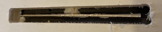
Woodies time!
When woodies are done, and the mill is back home, you can turn of the dustcollector and the mill. But leave the shopbot on!
Take of your shoes, climb on top of your stock on the shopbot with a handdrill and a box of woodies and drill woodies in the places where they should be.
You use your own weight to keep the stock down when you are putting the woodies in. Otherwise they might pull the stock from the sacrificial layer ruining your carefully measured Z.
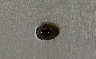
a lovely woody witting in his woody hole feeling all woody
Remember where I said that I put the x and y origin a centimer to far into the material. This was the moment I found out as some of the woodie hole (2 to be exact) where on the edge of the stock...
Can we now do the actual milling?!
Yes, we can.
Observations during milling:
- Around the 11 second mark in the video above amazing feature #2 (penholder) is not made. I selected profile here as profile action, where it should have been pocket.
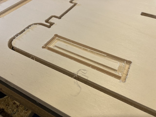
that does not hold pens well
- tiny parts, like some 41mm holes profiles need a bigger tab then the 5x5mm I used. One came loose and was luckily sucked up into the dustcollector, instead of becoming YAWTSCKY.
- On the other hand, when you drill profiles that are 12 mm wide, and your drill is 5mm, then it is maybe not necessary to use a tab, only to hole a tiny slice of 2mm in the middle in place...
- some rigs between profiling and pocketing actions remained. Henk asked me if I set the offset right. I am not sure if I did... But these rigs can easily be removed, so why worry about the offset... right..?
Finishing the work.
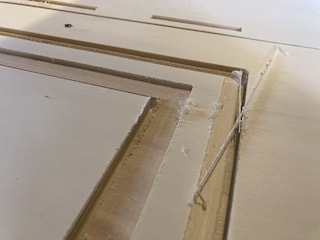
Now came the fun part; assembling the pieces! But first we have to sand the edges as they might be rough form the milling. Or did you think that that sanding paper was put there by accident?
I sand the sides and polish the tabs. And then comes the realization that ALL the pockets are too small. Or ALL the tabs are too big. OR BOTH! Depending on your point of view...
None of this whole damn thing seems to fit. So I sand and polish some more. But still... there are also hard to polish parts as little holes and
So maybe there was something more to the offset...
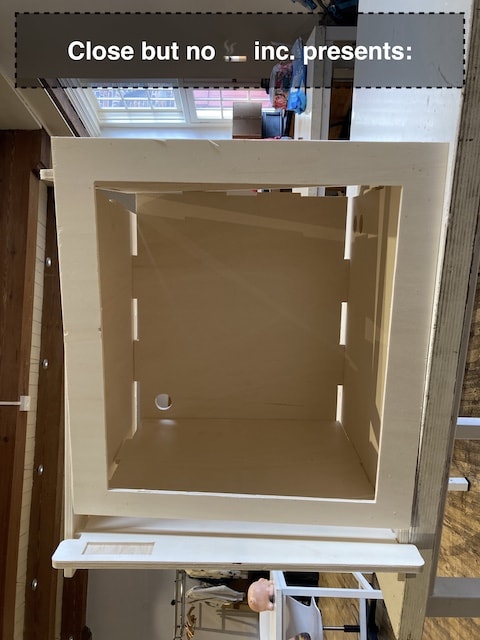
I tried sanding, polishing and some other tricks, but the difference was too big. Also I found I forgot to mill two profiles on the back part; so even if all had fitted and the offset would have been just fine, I still wouldn't have been able to assemble the whole damn thing.
Time consideration
So when you use all powerfull computerized programs and tooling, you can make amazing things fast, no?
| Task | Description | Time needed to do it | Estimate when experienced |
|---|---|---|---|
| Modelling | Making the design in Fusion. Including restarting twice | 18h | 4h |
| VCarve | Setting all the paths and cuts and tools | 2h | 30min |
| Shopbot | Setting up the machine and software | 1h | 30min. |
| Woodies | cutting and drilling in the woodies | 20min | 15min |
| Milling | leeting the shopbot work | 1h | 1h |
| Finishing | Sanding the pieces and correcting mistakes | 3h | 60min. |
| TOTAL | - | 25 hours and 20 minutes | 7 hours and 15 minutes. |
In other words: I spend over 3 whole working days for a piece of failed furniture. With some experience I think I can successfully make a piece of furniture, but still a full day of work will be needed to get the raw shape ready. Probably another day is needed for proper sanding and painting...
It all sucks big time and I am not happy... luckily I found that NASA has a dedicated website with 3D models for printers...
Things that went wrong
- I did not measure (well) the amount of wood I needed for the machine homes I wanted to create. Also the box was way larger then really needed: I just used all the available deskspace I have for these machines and figured that a little extra space inside the box would be nice and welcome.
- Fusion eats a lot of my time. I think this is a good investment as the tool will surely help me cerate nicer things in the future. But it is annoying that a lot of time goes into the tool instead of into making something.
- There are so many variables to check that you need to internalize some or make an extensive checklist of all settings. In this case I missed he offset variable...
- It will twice as much time as you expect. Also when you already took that into account.
Thing I will do differently next time
- The shopbot can help you to make great things that will last a long time: furniture and other wooden shapes that, when treated well, can last for decades. Why rush in a week to make something you want to use for very long?
- make little test runs on a small milling machine or with a laser cutter with cheap material: less waste means more freedom to play
- if you need to rush; make something that is not functional. If it doesn't need to perform a function, it is also no problem if it fails.
- Take your time