

Electronics Design:
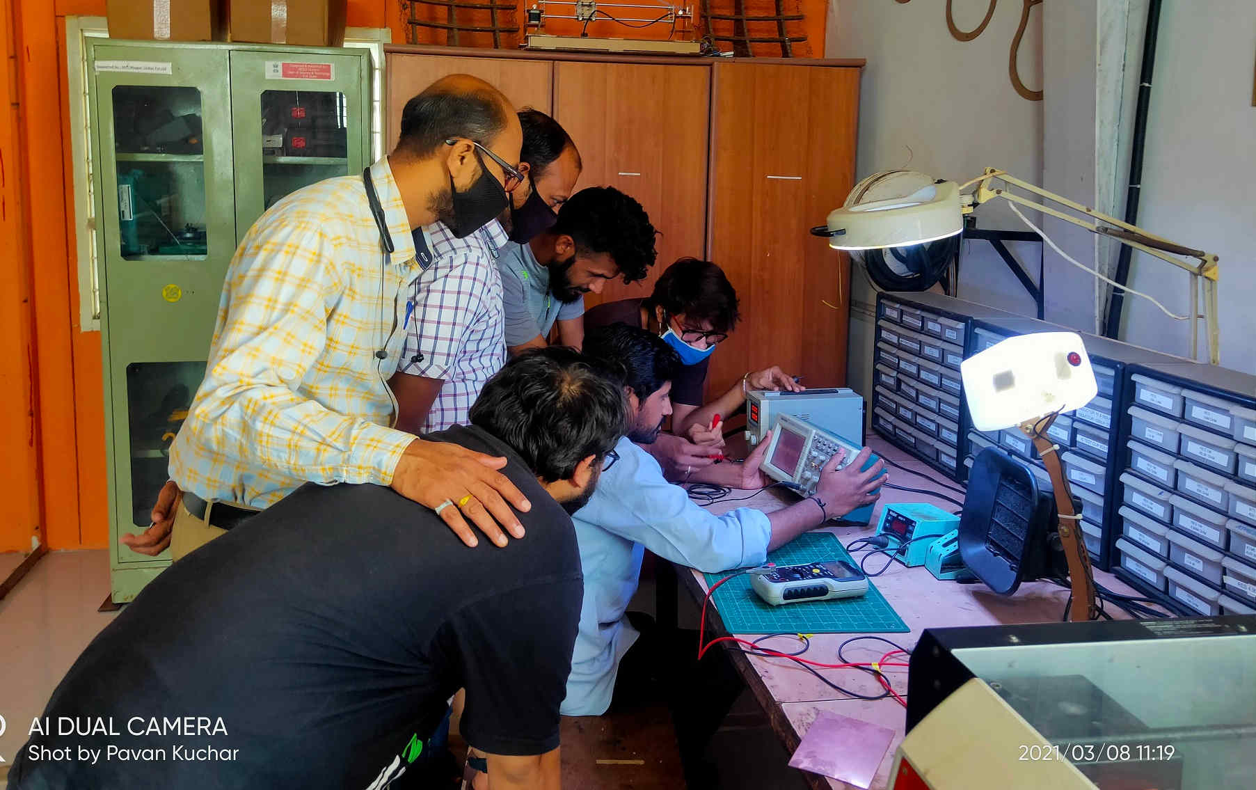
In this Sixth week of Fab Academy, we had room to test the various electronic equipments in our lab
We also had to redraw one of the hello world board and attach a LED, Switch / Button to it.
Objective:
1. Group assignment:
This week is having the following Objectives for the Group-
- Use the test equipment in your lab to observe the operation of a microcontroller circuit board (in minimum, check operating voltage on the board with multimeter or voltmeter and use oscilloscope to check noise of operating voltage and interpret a data signal)
- Document your work (in a group or individually)
Test Equipments available in our FabLab-0 at Vigyan Ashram, Pabal are:
Multimeter:
A multimeter, also known as a volt-ohm meter, is a handheld tester used to measure electrical voltage, current (amperage), resistance, and other values. Multimeters come in analog and digital versions and are useful for everything from simple tests, like measuring battery voltage, to detecting faults and complex diagnostics.The primary advantage of digital testers is the easy-to-read and highly accurate digital readout.
We have Megger AVO-830 Multimeter. We have tested the Continuity of the circuit, Capacitance, Voltage, Polarity and Current with this. This Digital meter displays readings on the screen. For checking, we have to turn the knob in the center of the tester to select the function and appropriate range for the specific test. To take a reading, you touch the bare metal pointed end of each lead to one of the terminals or wires to be tested.
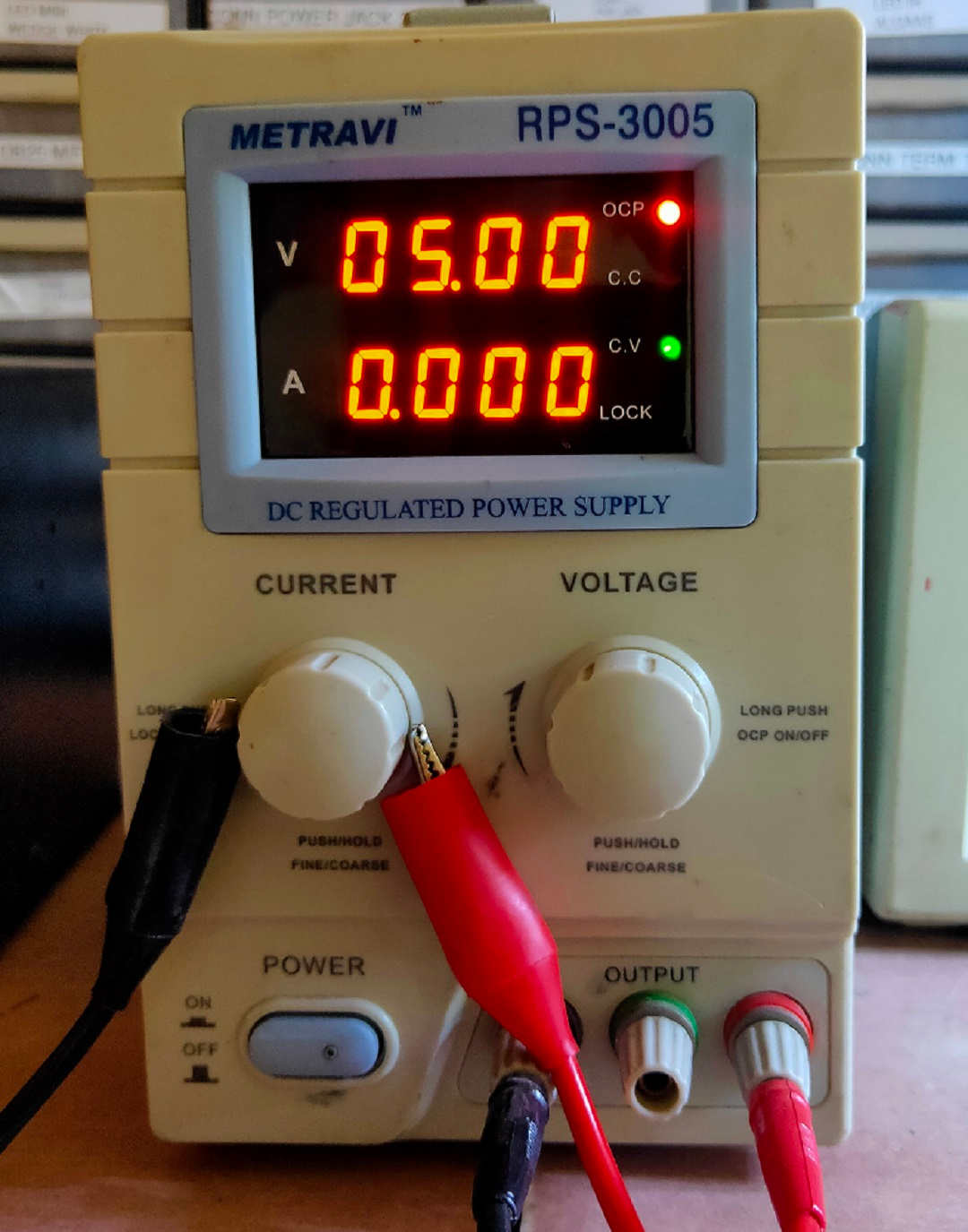
Regulated Power Supply:
A regulated power supply converts unregulated AC (Alternating Current - 230V) to a constant DC (Direct Current-5V). A regulated power supply is used to ensure that the output remains constant even if the input changes. A regulated DC power supply is also known as a linear power supply, it is an embedded circuit and consists of various blocks.
.jpg) Multimeter (Megger) Multimeter (Megger) |
 Regulated Power Supply Regulated Power Supply |
|---|
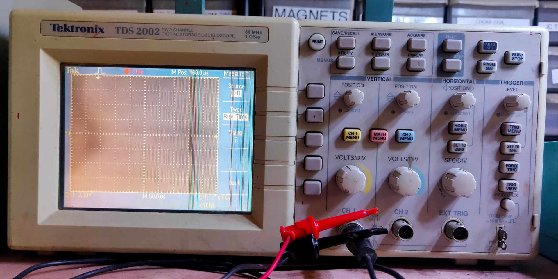
Digital Storage Oscilloscope(DSO):
The digital storage oscilloscope is an instrument which gives the storage of a digital waveform or the digital copy of the waveform.
The DSO can be used to check the faulty components in various circuits, measure ac as well as dc voltages and current. It is also used to save signals, so that it can be compared to or processed; to measure frequency, time period, time interval between signals etc. and to observe the V-I characteristics of diodes, transistors.
 Details here.
2. Individual assignment:
Redraw one of the echo hello-world boards or something equivalent, add (at least) a button and LED (with current-limiting resistor) or equivalent input and output, check the design rules, make it, test it.
Learning Outcomes:
- Select and use software for circuit board design
- Demonstrate workflows used in circuit board design
Checklist:
Linked to the group assignment page ✔
Documented what you have learned in electronics design ✔
Explained problems and how you fixed them, if you make a board and it doesn't work; fix the board (with jumper wires etc) until it does work. ✔
Included original design files (Eagle, KiCad, - whatever) ✔
Included a ‘hero shot’ of your board ✔
Loaded a program and tested if your board works ✔
Opening Quotes:
- Anyone Can Be An Electronics Designer; Curiosity is the only requirement
- No matter how high you go, we will always ground you
- Our potential does not drop across any resistance.
- Resistance is Futile (if less than 1 ohm)
Electronics Design:
Electronic circuit design involves the selection and interconnection of physical devices in a variety of topologies to meet performance specifications, environmental requirements, power and cost budgets, operating life requirements, and other design constraints in agreement with an overall schedule.
The details of the Group assignment could be found here.
The flow of this Assignment is as follows:
- Types of Electronics Devices: Active and Passive
- About ATtiny 45 microcontroller
- About Eagle Software for designing the circuit board
- Design PCB using Eagle Software
- Milling PCB by SRM 20 Milling machine
- Programming PCB through ATtiny45
Useful Electronic Components:
Electronic devices are components for controlling the flow of electrical currents for the purpose of information processing and system control. Electronic devices are usually small and can be grouped together into packages called integrated circuits. This miniaturization is central to the modern electronics boom.
- Capacitors - little towers of power that store electricity
- Resistors - reduce current and are used in almost every project
- Switches - good ones to have: SPST, SPDT, DPDT, and pushbutton
- LEDs - Light Emitting Diodes, let there be light
- Jumper or hookup wire - connects everything in electronics
- Batteries and battery clips to supply the power to your projects
- Protoboard, also known as perfboard, or breadboard is what you mount all that stuff on Integrated circuits, specifically digital to analog converters, and 555 timers are essential, as well as IC sockets for them, so that you can easily replace them in case one malfunctions.
- Motors are great to have on hand
- Potentiometers are variable resistors, used in loads of audio projects
- Voltage regulators are an essential. The 2 most used are the 7805 and 7812
- Other components you may also want to have on hand: USB ports, DIP switches, 7-segment displays, reed switches and relays
- Grab Bags are an inexpensive way to get a wide range of miscellaneous components
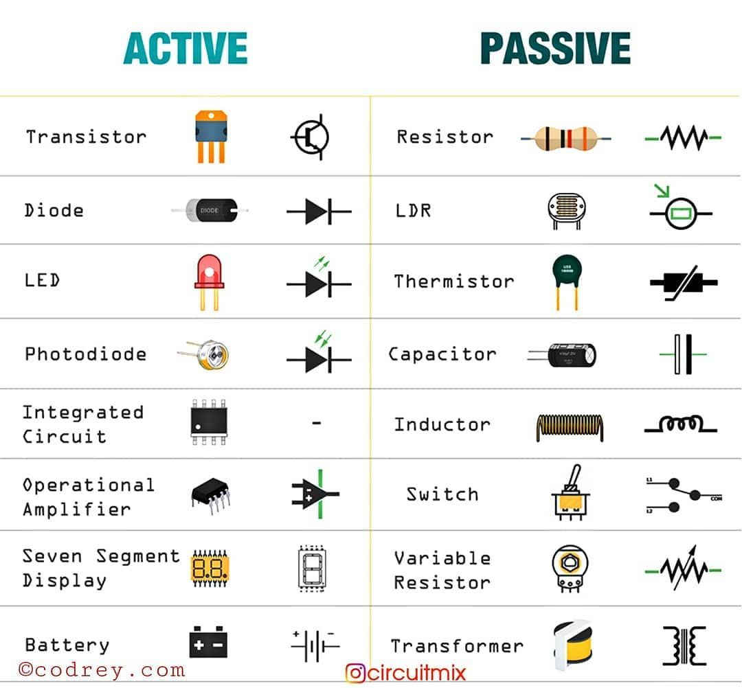
Types of Electronics Devices: Active and Passive:
Whether the electronic component is Active or Passive depends on How it is connected in the Circuit.
Active components are parts of a circuit that rely on an external power source to control or modify electrical signals. Active components such as Diodes, Transistors, silicon-controlled rectifiers (SCR), Integrated circuits etc. use electricity to control electricity.
Passive components like resistors (opposes change in current and voltage in the circuit), transformers, and diodes don’t need an external power source to function. These components use some other property to control the electrical signal. As a result, they only require the current traveling through the connected circuit. Resistors impede the flow of electrons without introducing more electricity into the system. The energy is dissipated in the form of Charge (Capacitors), Magnetic field (Inductors), Heat (Resistors)
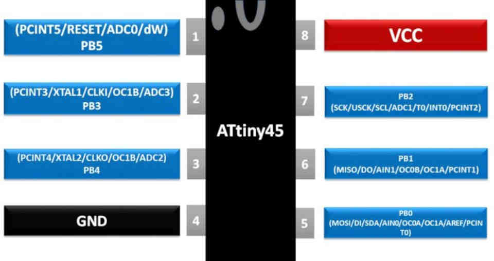
About ATtiny 45:
I had already made an ATtiny45 PCB in the Electronics Production week and programmed it to be used as a Programmer. Here, I will be using the same for programming the redrawn PCB with two LED and Switch button.
Details here
ATtiny (also known as TinyAVR) are a subfamily of the popular 8-bit AVR microcontrollers, which typically has fewer features, fewer I/O pins, and less memory than other AVR series chips. The first members of this family were released in 1999 by Atmel (later acquired by Microchip Technology in 2016).
ATtiny45 is a high-performance, low-power Atmel 8-bit AVR RISC-based microcontroller combines 4KB ISP flash memory, 256-Byte EEPROM, 256B SRAM, 6 general purpose I/O lines, 32 general purpose working registers, one 8-bit timer/counter with compare modes, one 8-bit high speed timer/counter, USI, internal and external Interrupts, 4-channel 10-bit Analog to Digital converter, programmable watchdog timer with internal oscillator, three software selectable power saving modes, and debug WIRE for on-chip debugging. The device achieves a throughput of 20 MIPS at 20 MHz and operates between 2.7-5.5 volts.
By executing powerful instructions in a single clock cycle, the device achieves throughputs approaching 1 MIPS per MHz, balancing power consumption and processing speed.
Applications of ATtiny 45:
ATTINY45is an 8 pin AVR controller and so application program can be developed in AVR IDE which has many references. ATTINY is popular because it is one of cheapest. Also, it provides many features in lesser pins. With various POWER SAVING modes it can work on MOBILE EMBEDDED SYSTEMS. Because of its small and compact size it can be put in many small boards. With Watchdog timer and other features the use on ATTINY45 is further promoted.
- Used in development boards.
- Hobby projects
- Drivers
- Industrial control systems.
- SMPS and Power Regulation systems
- Analog signal measuring and manipulations.
- Embedded systems like coffee machine, vending machine.
- Display units
- Peripheral Interface system
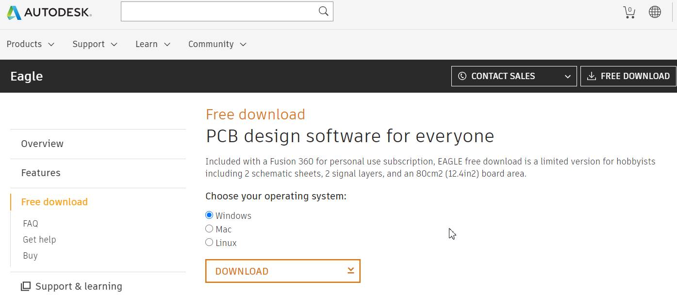
About Eagle Software:
EAGLE is electronic design automation (EDA) software that lets printed circuit board (PCB) designers seamlessly connect schematic diagrams, component placement, PCB routing and comprehensive library content.
Various Features of Eagle:
- Easy-to-use schematic editor in EAGLE
- Powerful PCB layout: Bring your design to life with a wide range of PCB layout tools in EAGLE.
- Workflows: Integrated ECAD to MCAD
- EAGLE resources: Tutorials, Webinars and Forums
Designing the PCB:
There are various softwares available both free and paid for PCB design. TinkerCAD, KiCAD, Eagle, Virtual BreadBoard, Gritzing, Deeptrace etc. are few examples. I have tried TinkerCAD and then switched to Eagles for designing the PCB.
Steps in Designing the PCB with Eagle Software by Autodesk:
First of all, I downloaded the latest version of Eagle software from the website. It is free for use. Downloading Eagle 9.6.2 software in the Laptop.
Step2. Adding Eagle libraries : Add the 'Fab library'(eagl_fab) in the Eagle interface. By adding this library, we get access to the list of different components required in circuit designing.
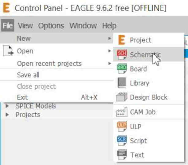
- Step3. Open the Eagle software and goto file select menu then select new Schematics under Project.
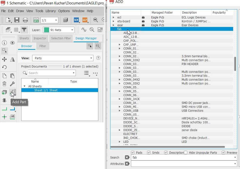
- Step4. Adding components in new schematics.
- Go to add components. Click on fab library and select component have to add in schematics
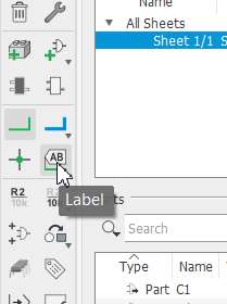
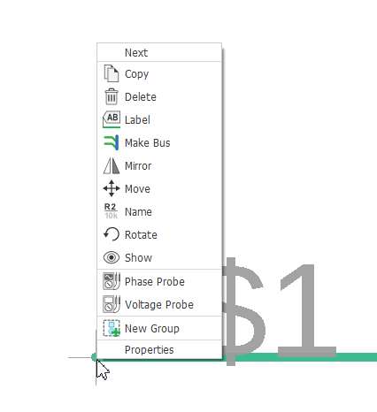
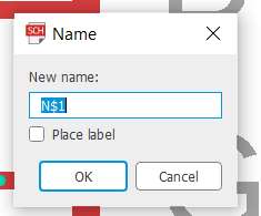
- Step4. Apply the Net to the selected components and then label them. Name and apply the value to the components.
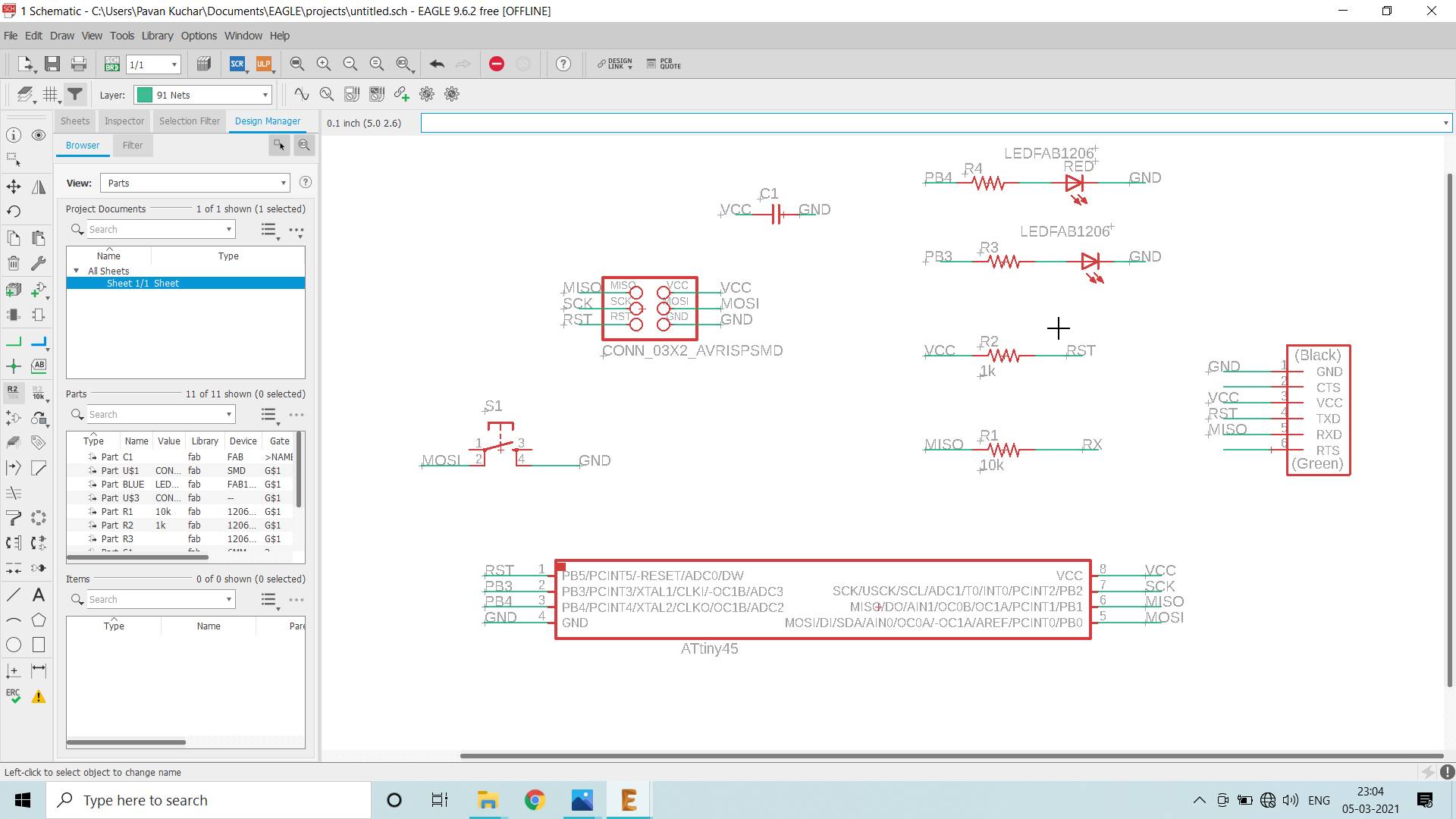
- Step5. Add, Label and Connect all the components in the schematics as shown in the image.
- Components used by me for this Assignment are:
- Step6.Check the errors in schematics board before switching to the board.
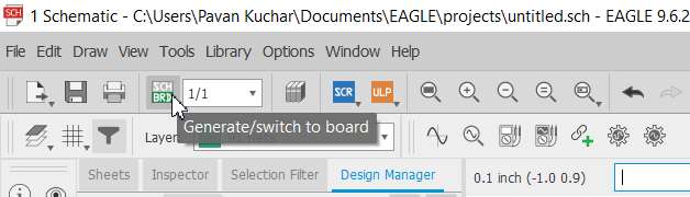
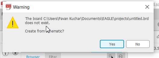
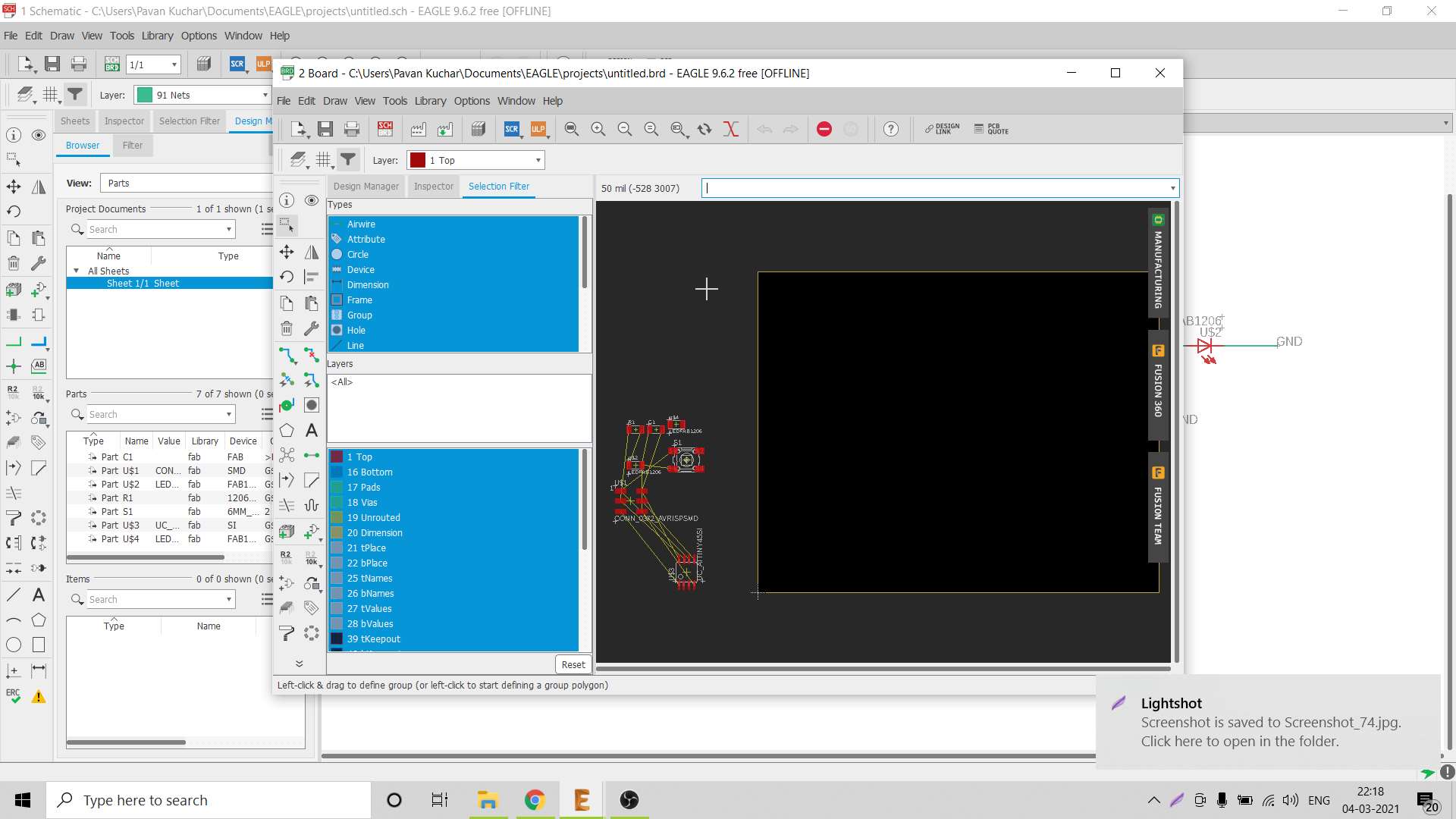
- Step7. Now Generate /switch to board.
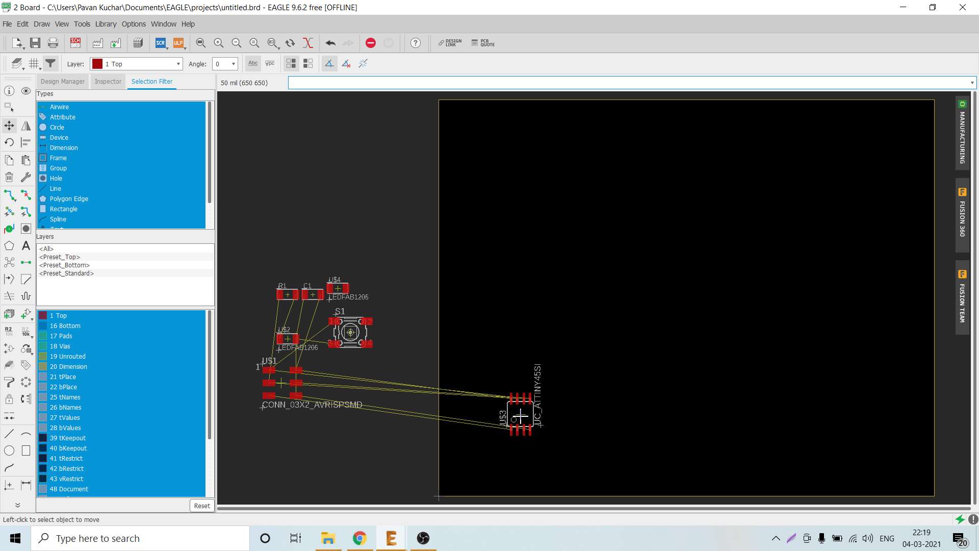
- Once the Board file is created, drag the components on the board from the outside.
- Once all the components are gragged on the Board, arrange them in such a way that they could be moved or rotated to have minimal rastness.
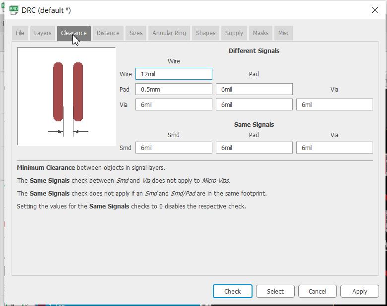
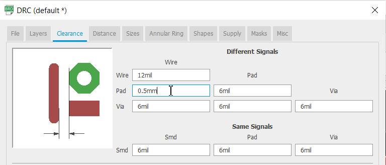
- Step8.Check DRC in board
- Step9.Placing components in PCB layout area
- After setting the DRC, we may proceed with AutoRouting or we may even Route Airwire (Hand Routing) the PCB. I used the AutoRouting option. At the end, when the traces were very nearer to each other, I used Hand Routing to increase the distance between the traces.
- Step10. Export the PCB layout
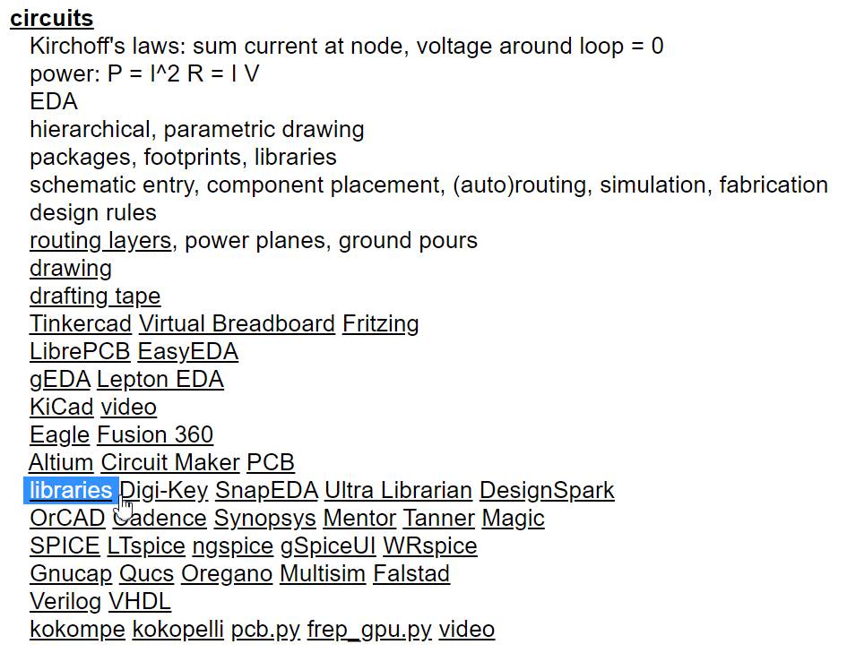
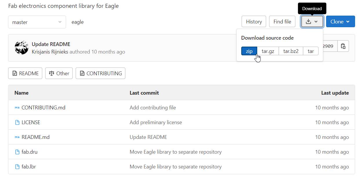
For this, Go to the website of Fabacademy2021 then to Schedule, click on Electronic Design; Scroll down and click on libraries.
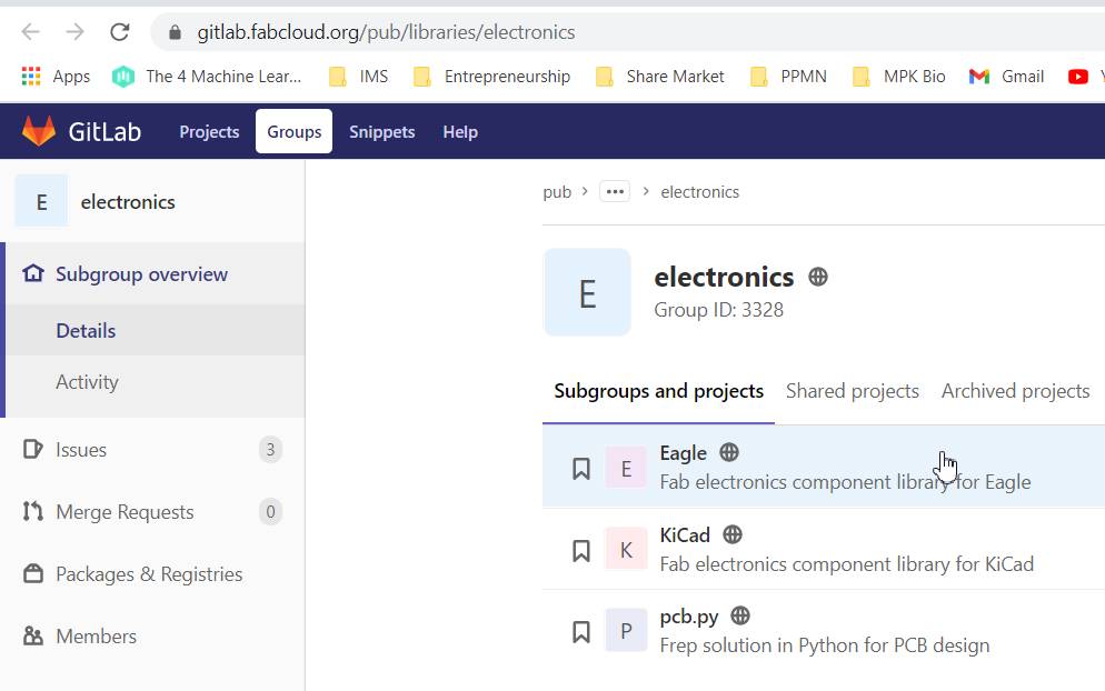
You would be directed to the page of github. In github, Click on Eagle electronics components library. Go to download zip folder. Add the Fab.lbr file in Eagle library.
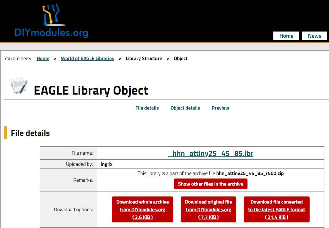
For future reference, you may also download the atmel library. For atmel library, goto DIYmodules.org. goto search engine for Eagle libraries. Search for ATtiny45 (SMD) and download atmel.lbr. Add in Eagle library.
 |  |  |
|---|
| Component | Quantity in No. | Capacity/Description |
|---|---|---|
| ATtiny45 Microcontroller | 01 | |
| Resistors | 04 | 02 of 100 ohms, 01 of 1K and 01 of 10K ohms |
| Capacitor | 01 | (C1206Fab)1 micro Farad |
| LED (Light Emitting Diode) | 02 | 01 Blue and 01 Red |
| Switch | 01 | Omron 6 mm Tactile |
| Connector Pins | 02 | 3x2 AVR ISP Header and 6 Pin FTDI Header |
Goto the Tools click on ERC(Electrical Rules Check) which shows the details of Errors and warnings if the components are not connected or connected in wrong way. Check all the warning and fix them.
Goto the top of interface and click on SCH/BRD(switch to board). This will begin the process of generating a PCB layout based on the components and wiring in your schematic. The Board would be opened in the new window.

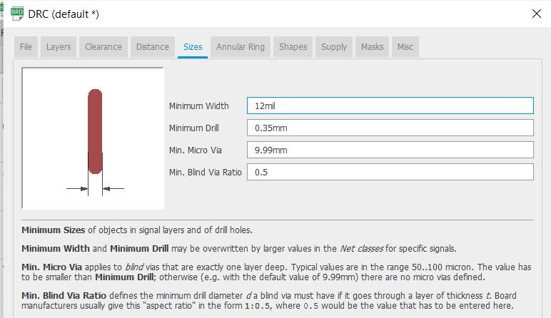
Before generating the PCB board design go through the DRC. DRC means Design rule check is the option provided in the eagle to ckeck the trace width in our board design. This will help us to design the board by considering all the milling limitations to have considerable distance between two traces and pads.
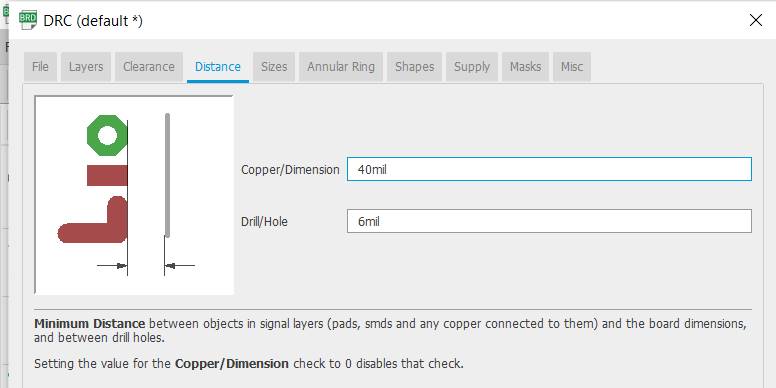
Place the components on the Board in such a way that there is minimal crossing of the connections.
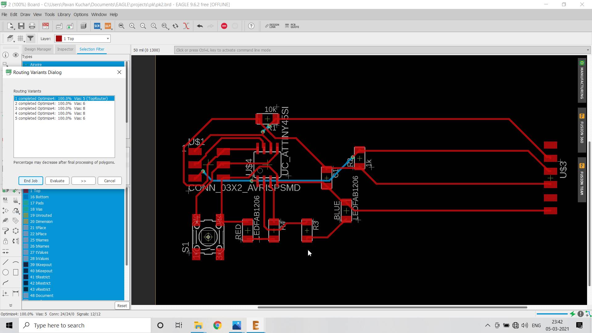
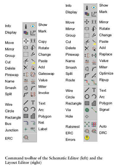
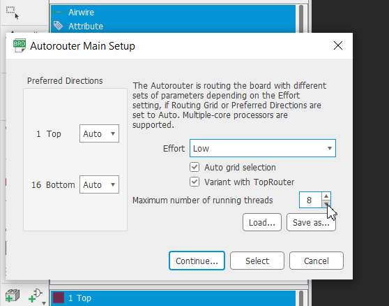
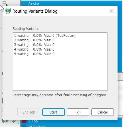
For auto routing, arrange all the components on the layout. Click the Auto router Command Toolbar of the Schematic Layout Editor. In the Setup, click on continue. In Routing Variants dialogue box, click on start, optimize completed.
 |  |
|---|
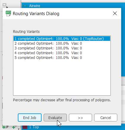
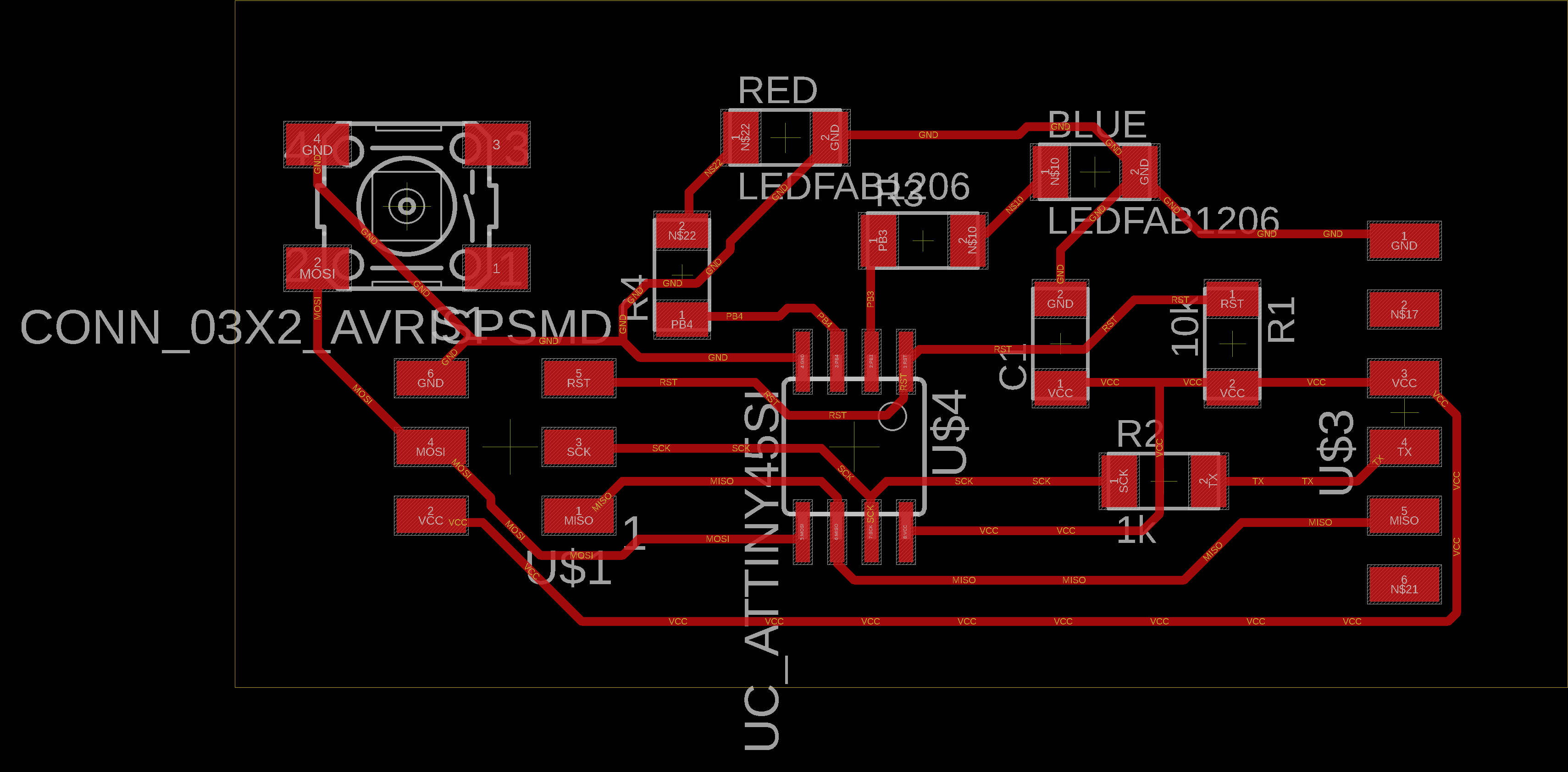
Note that the vias should become zero and select top router (best auto routed path for given circuit). Try various options of Moving, Rotating, Rastness for getting the AutoRouting. The Blue Lines in the image after the Auto Routing show that the connections are not optimally routed and the lines are crossing each other. ReRoute until all the Vias are Zero.
For hand routing, arrange all the components on the layout. Click on Route Airwire. Arrange all the route one by one such that no two connecting wires cross each other.
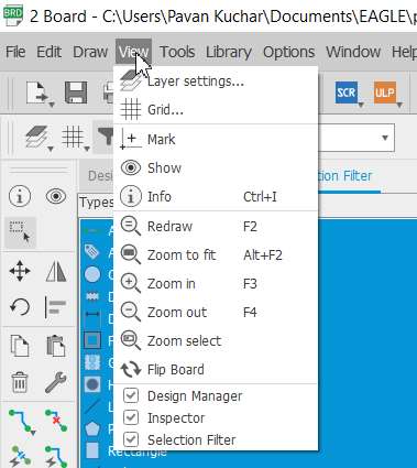
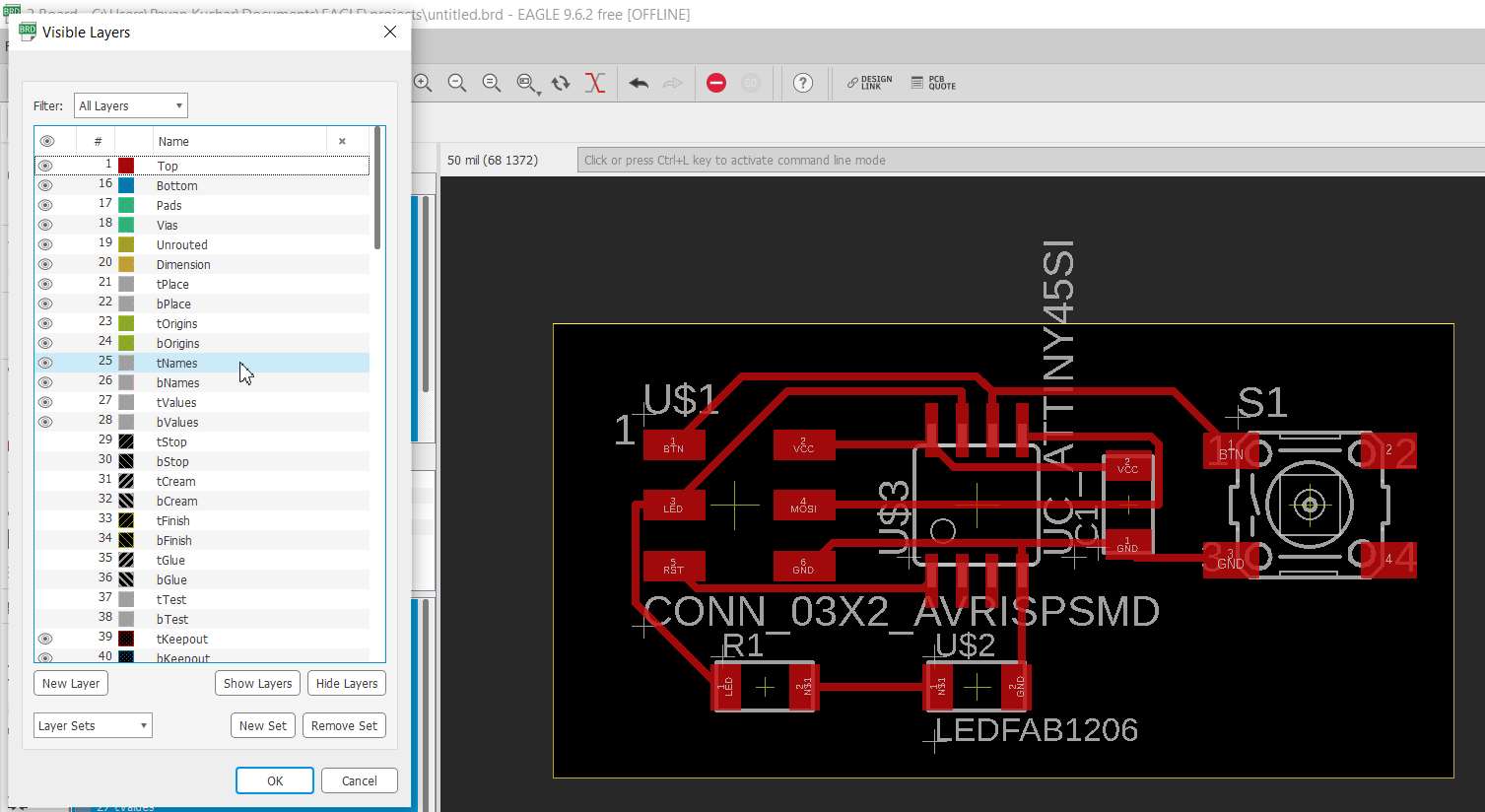
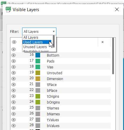
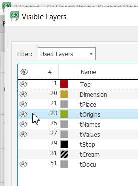
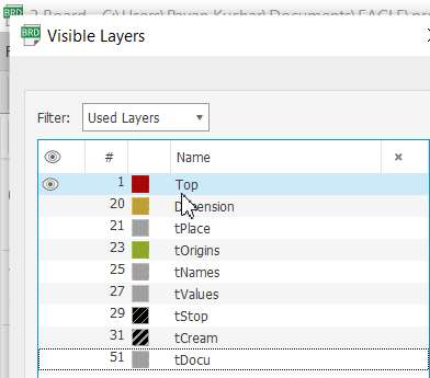
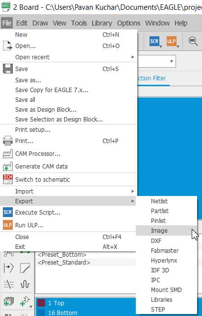
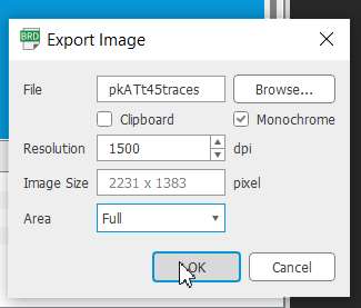
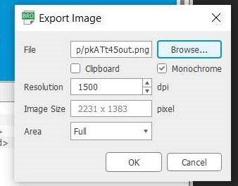
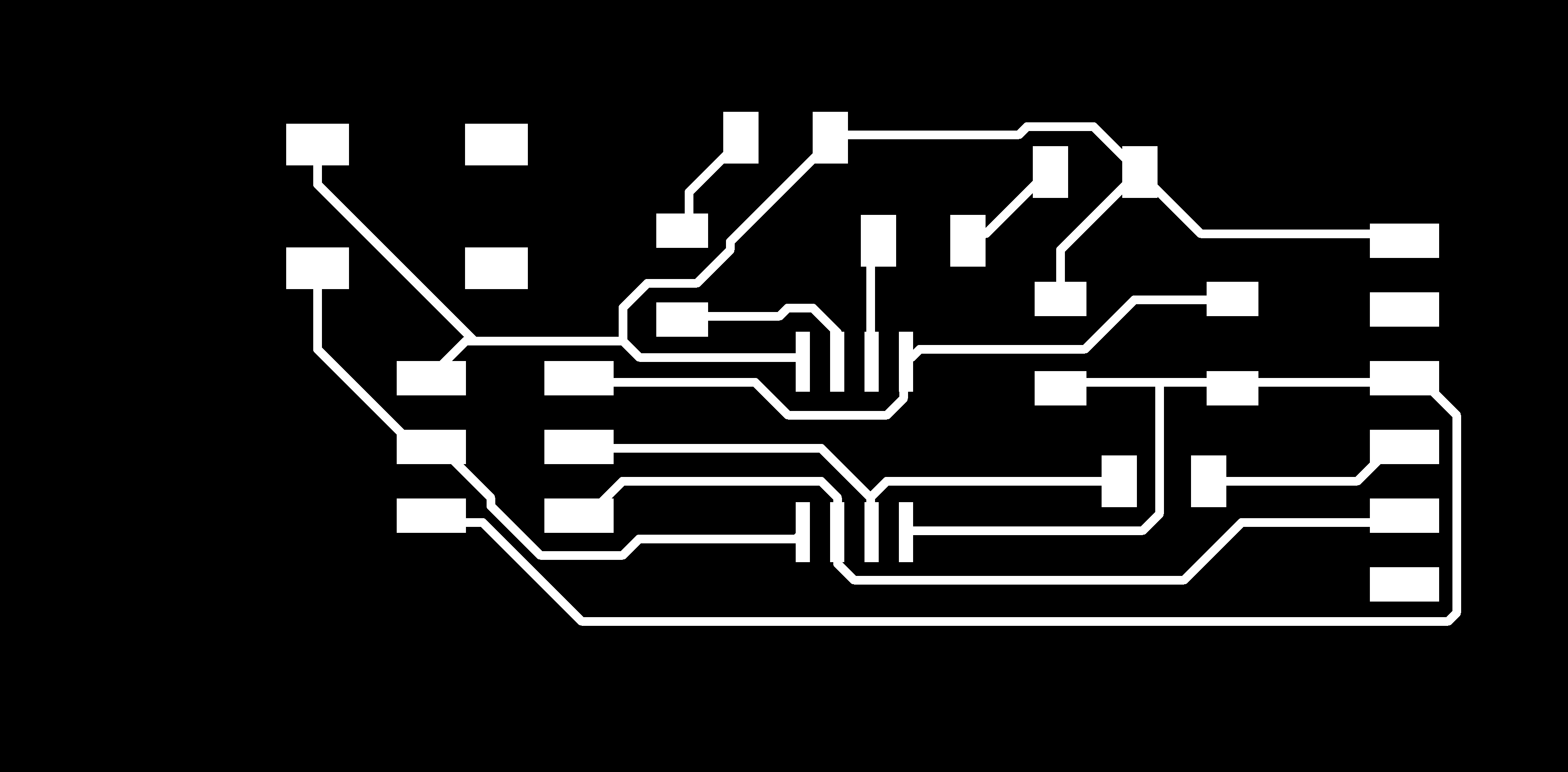
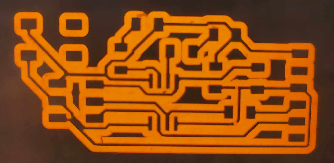
Remove all the unwanted layers and prepared the PCB image for export. Goto file menu click on export select image. Set the name,location and resolution of image.
 |  |
|---|
 |  |
|---|
 |  |
|---|
 |  |
|---|
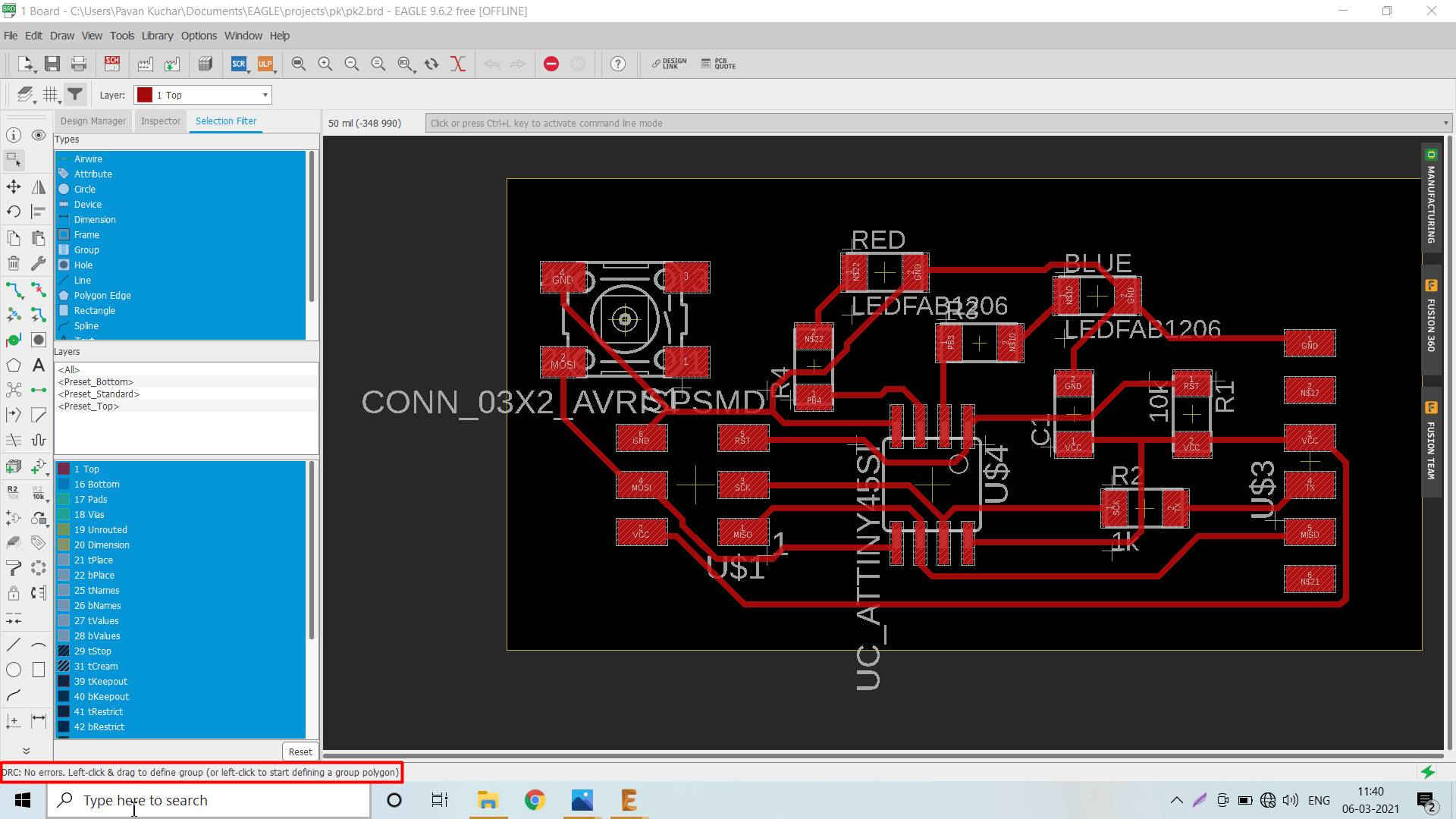 After proper Routing, NO Errors is displayed in the Status Bar.
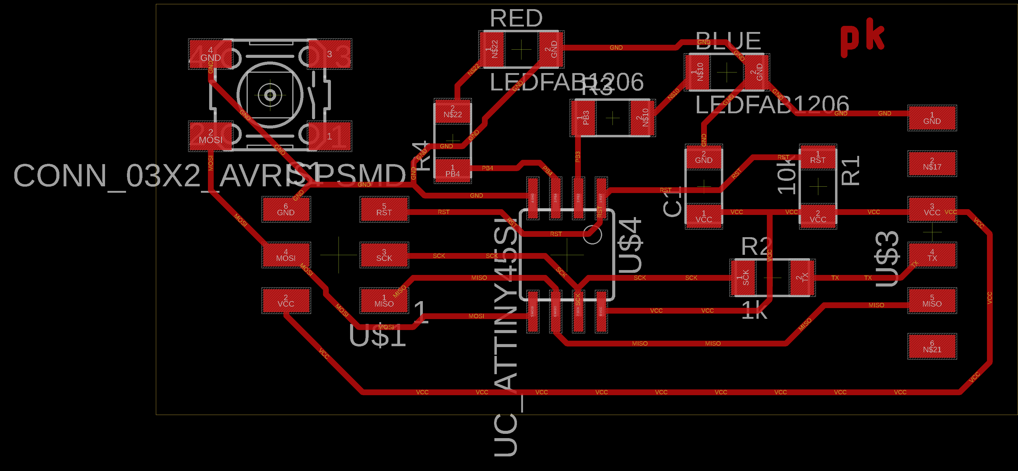
 Auto Routed PCB Auto Routed PCB | .png) Hand Routed PCB Hand Routed PCB |
|---|
PCB milling by SRM 20
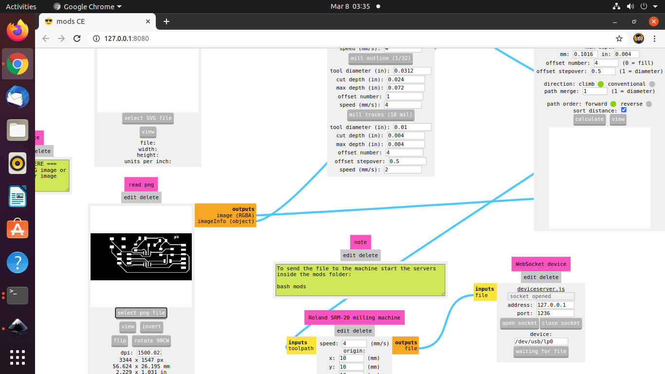
After the PCB design, I milled the PCB using SRM-20 Machine. The details of the Milling Process could be found in the Electronics Production Week. The flow of the process is as:
- Run the Mods of SRM-20 on the Computer
- Select the .png image, check its dpi (resolution)
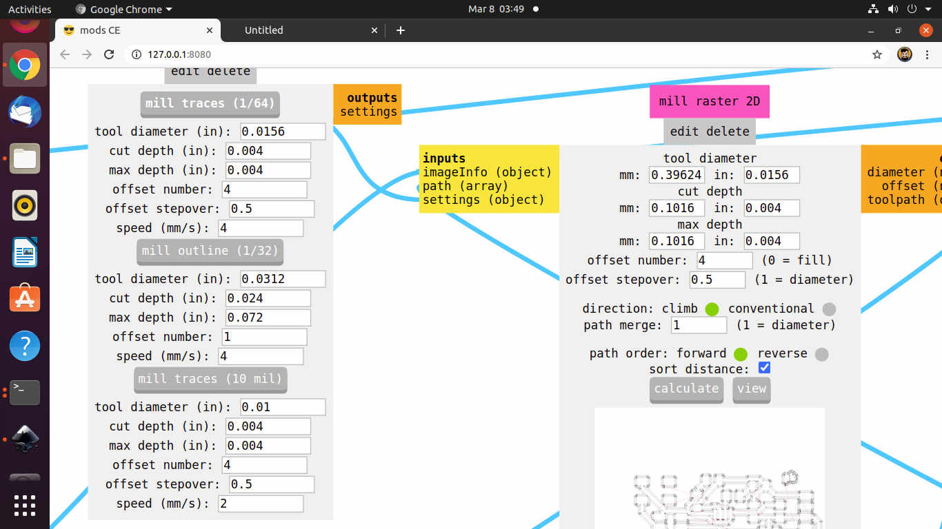
- Select Mill trace (1/64") for milling trace of the PCB.
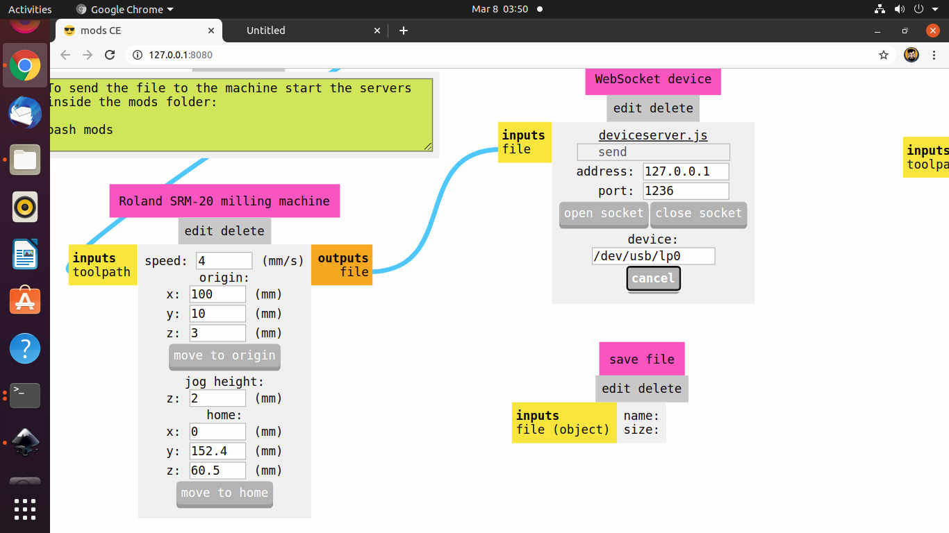
- Set the optimal parameters for the machine like Origin, Cut Depth, Max Depth
- Calculate the path, Open Socket and send the file to the machine for milling.
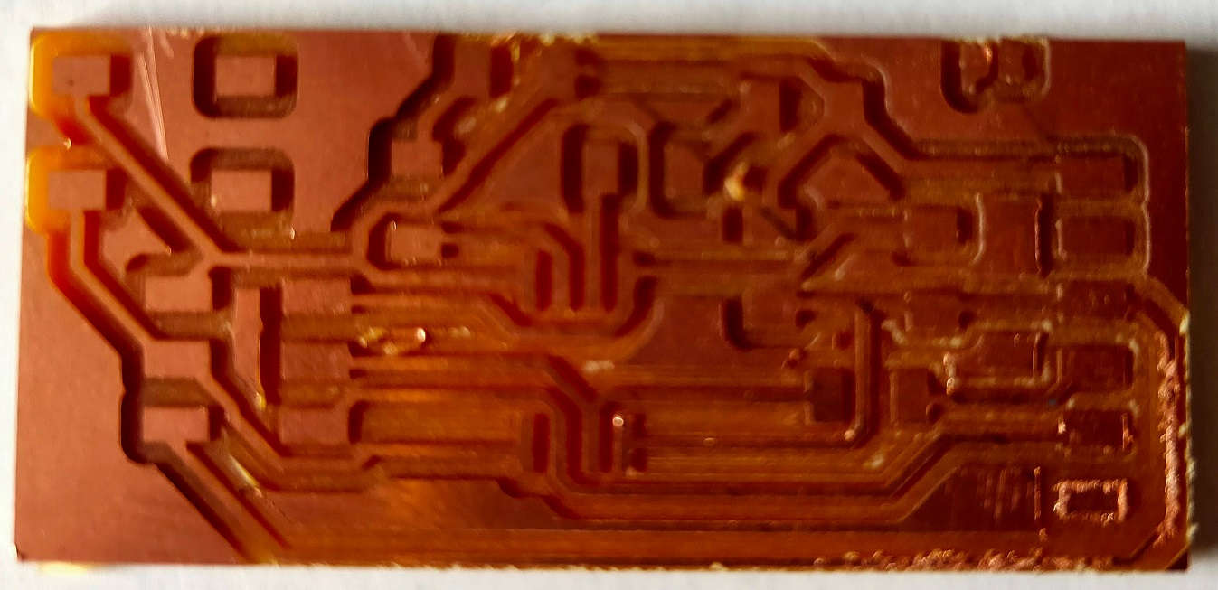
I milled two PCB plates because the first PCB had two traces on the left down side joined with each other. Also, the traces at some places were burred and discontinued and I forgot to put my name over the PCB. Then, I hand routed the PCB and milled again.
 Auto Routed PCB
 Hand Routed PCB
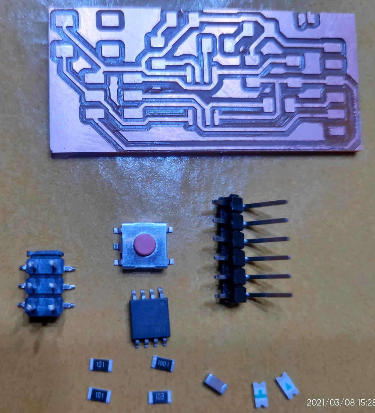
Stuffing and Soldering PCB:
After the completion of Milling of PCB plate, I soldered the components. I checked the polarity of the LED (Diodes), Capacitance of Capacitors and Resistance of the Resistors. I also calculated the capacity of the current limiting Resistor required for the LED.
Components used in the PCB:
| Component | Quantity in No. | Capacity/Description |
|---|---|---|
| ATtiny45 Microcontroller | 01 | |
| Resistors | 04 | 02 of 100 ohms, 01 of 1K and 01 of 10K ohms |
| Capacitor | 01 | (C1206Fab)1 micro Farad |
| LED (Light Emitting Diode) | 02 | 01 Blue and 01 Red |
| Switch | 01 | Omron 6 mm Tactile |
| Connector Pins | 02 | 3x2 AVR ISP Header and 6 Pin FTDI Header |
The capacity of the Resistor was calculated by using the formula: V=IxR where V is Voltage; I is the current and R is the Resistance. In this case, I referred the datasheet and found that the current is 10mA and the Voltage is 1.8V. So, a drop of 3.2 Volts will be required.
After putting the values in the formula and calculating, the value of the Resistors required came to be 180 ohms. But I have used Resistor of 100 ohms. Even the possibility of using two resistors of 100 ohms in parallel by stacking them up was thought.
I soldered all the components on the redrawn PCB plates.
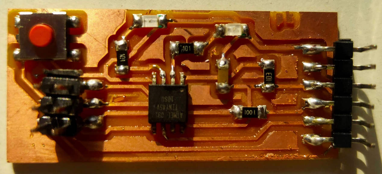
I again checked the Connectivity with the Multimeter to ensure proper Soldering and Connectivity. The third pin was not properly connected. It had a Cold Solder. So, I let some solder to flow and used flux to have proper solder on the third pin of the UPDI connector pin.
Programming the PCB:
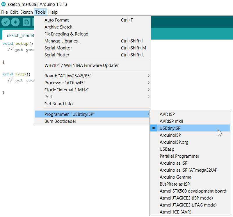
We had to make a helloworld PCB for this week. To check whether the PCB is properly soldered and can be programmed or not, we had to upload a program through USBtiny FAB ISP earlier made in the Electronics Week.
I first downloaded the Arduino IDE (2.0 beta version). But it was not operating properly as it was experimental version so i uninstalled it and downloaded the Arduino IDE 1.8.13 version.
The Guide for Downloading and Installing Arduino IDE could be found here.
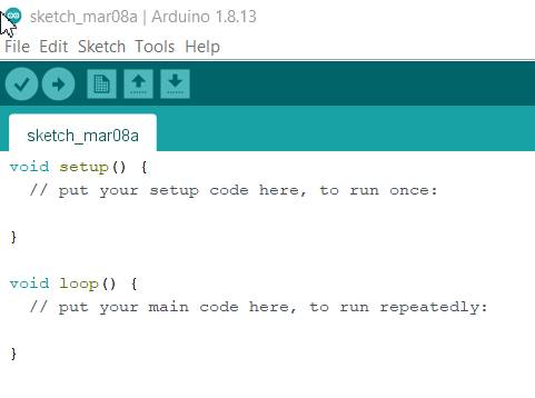
This is the Startup Window that will open up.
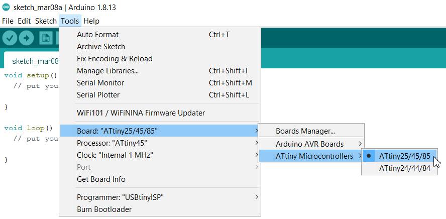
Arduino doesnt support the ATtiny 45. So, we have to update its library and add the required Programmer, Board, Processor. For this, I followed the process shown through images below.
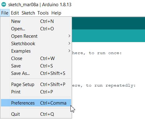
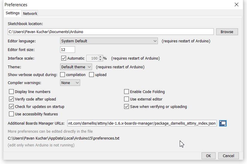
Go to the Preferences under File Menu.
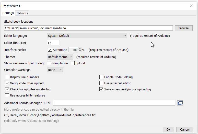
Input the Additional Board URL in the box.
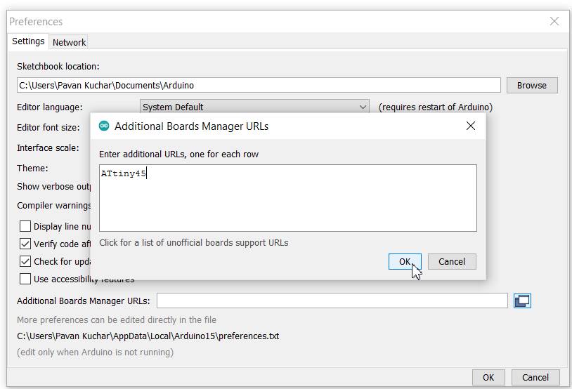
But if you dont have the URL, you may search it on the github platform. The link is https://raw.githubusercontent.com/damellis/attiny/ide-1.6.x-boards-manager/package_damellis_attiny_index.json
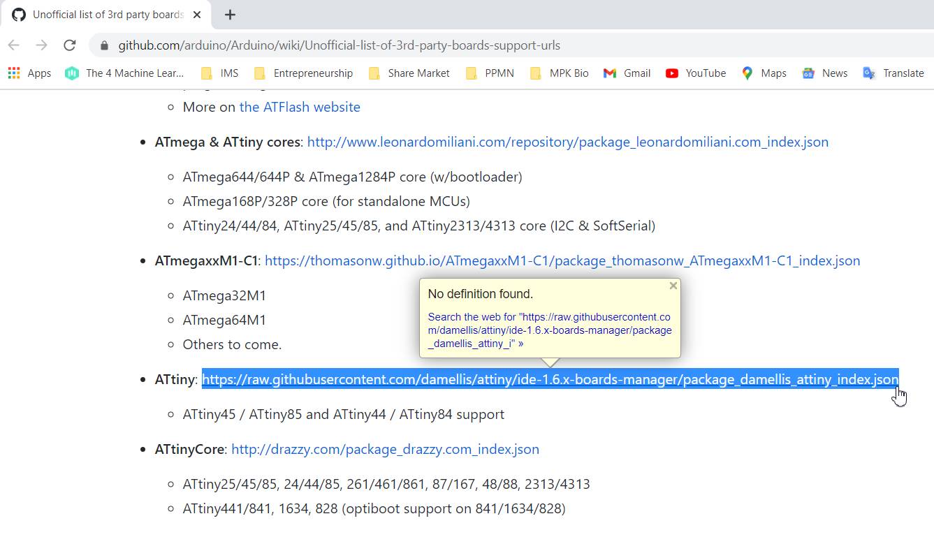
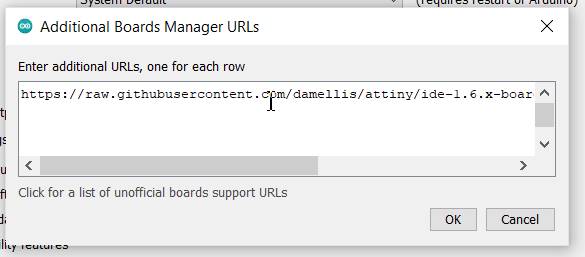
Copy the link and paste it in the box. Press OK.
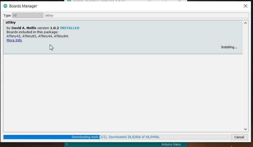
The Additional Board will be installed and can be found in the Tools Menu under Boards, Programmers and Processors.
After installation of all the required program, I had to program the PCB. I took the already made AVR Fab ISP which is used for programming other PCB.
- I connected the Fab ISP with ATtiny 45 PCB hello world board through AVR ISP connector pins.
- I used the ribbon cable to connect them.
- Only care to be taken to ensure that the GND, VCC pins of FabISP are connected to the GND and VCC of ATtiny45.
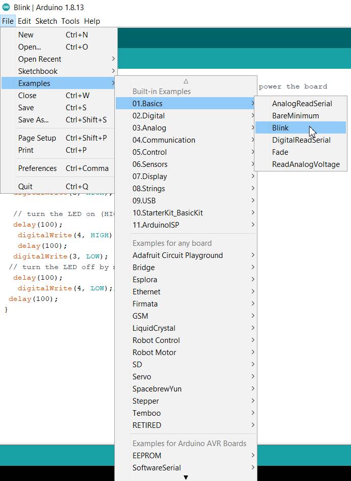
- Go to the Files Menu and click on the Examples, Basics and then on Blink.
- This will open the already existing program in the library.
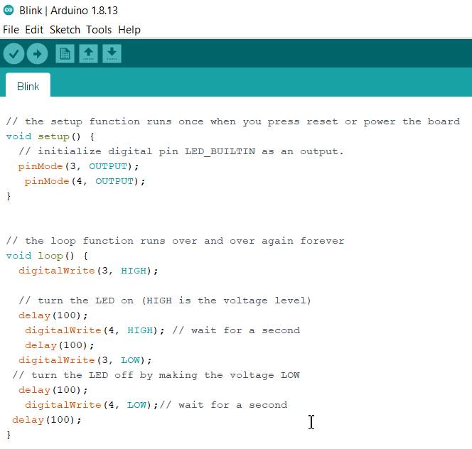
- The program could be edited as per the need. I have connected the LED to the Pin no.3, so I made changes in the program. I entered the specifications of other LED connected on Pin no.4
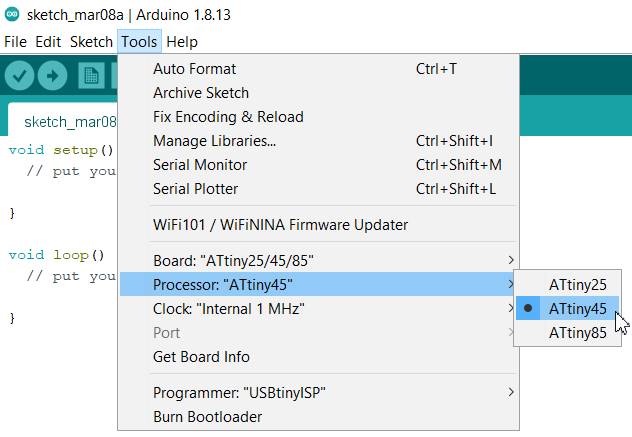
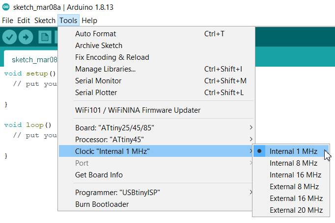
- I chose the Programmer, Board, Processor, Clock Speed.
- Yes! Hurray! the LED was blinking.
- Earlier the delay was of 1000 milliseconds i.e. 01 second. I changed it to 5000. But, it was very slow. So, i reduced it to 100 and then the LED started to blink faster.
- The Program is as under:
Summary:
We had to redraw the PCB, add atleast a LED, Switch and current limiting resistor after milling and soldering it and then test it by programmming it.
- Major issue I faced was in the routing of the PCB. Also, how to strategically choose pins for attaching the LEDs and various other components is important which would ease up the connections later on.
- I have learnt about the PCB designing through Eagle software.
- To some extent, I understood the components used in electronic devices and their work.
- I also learnt about programming the PCB.
- I havent used Route Airwire (Hand Routing extensively) which I have to work on.
Video Stream of the LED's Flashing after programming the ATtiny45: