

Computer Controlled Machining:
In this Seventh week of Fab Academy, we had room to test our creativity in making Something BIG and useful furniture
Objective:
1. Group assignment:
Details here.This week is having the following Objectives for the Group-
- Do your lab's safety training
- Test runout, alignment, speeds, feeds, materials, and toolpaths for your machine
2. Individual assignment:
Make (design+mill+assemble) something big (~meter-scale)
Learning Outcomes:
- Demonstrate 2D design development for CNC production
- Describe workflows for CNC production
Checklist:
Linked to the group assignment page ✔
Documented how you designed your object (something big) ✔
Documented how you made your CAM-toolpath ✔
Documented how you made something BIG (setting up the machine, using fixings, testing joints, adjusting feeds and speeds, depth of cut etc.) ✔
Described problems and how you fixed them ✔
Included your design files and ‘hero shot’ photos of final object ✔
Opening Quotes:
- "Simple Molecules combine to make Powerful Chemicals; Simple Cells combine to make Powerful Life forms; Simple Electronics combine to make Powerful Machines."
- "No matter how well you maintain your machines, how well you train your controllers or how carefully you care for your tools; problems will still pop up."
1. Group assignment:
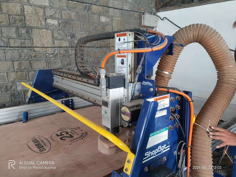
At FabLab-0, Vigyan Ashram, Pune; we dont have any ShopBot machine so we had to do this assignment in one of the reputed Engineering Colleges of Maharashtra i.e. College of Engineering, Pune (Govt. Autonomous Institute).
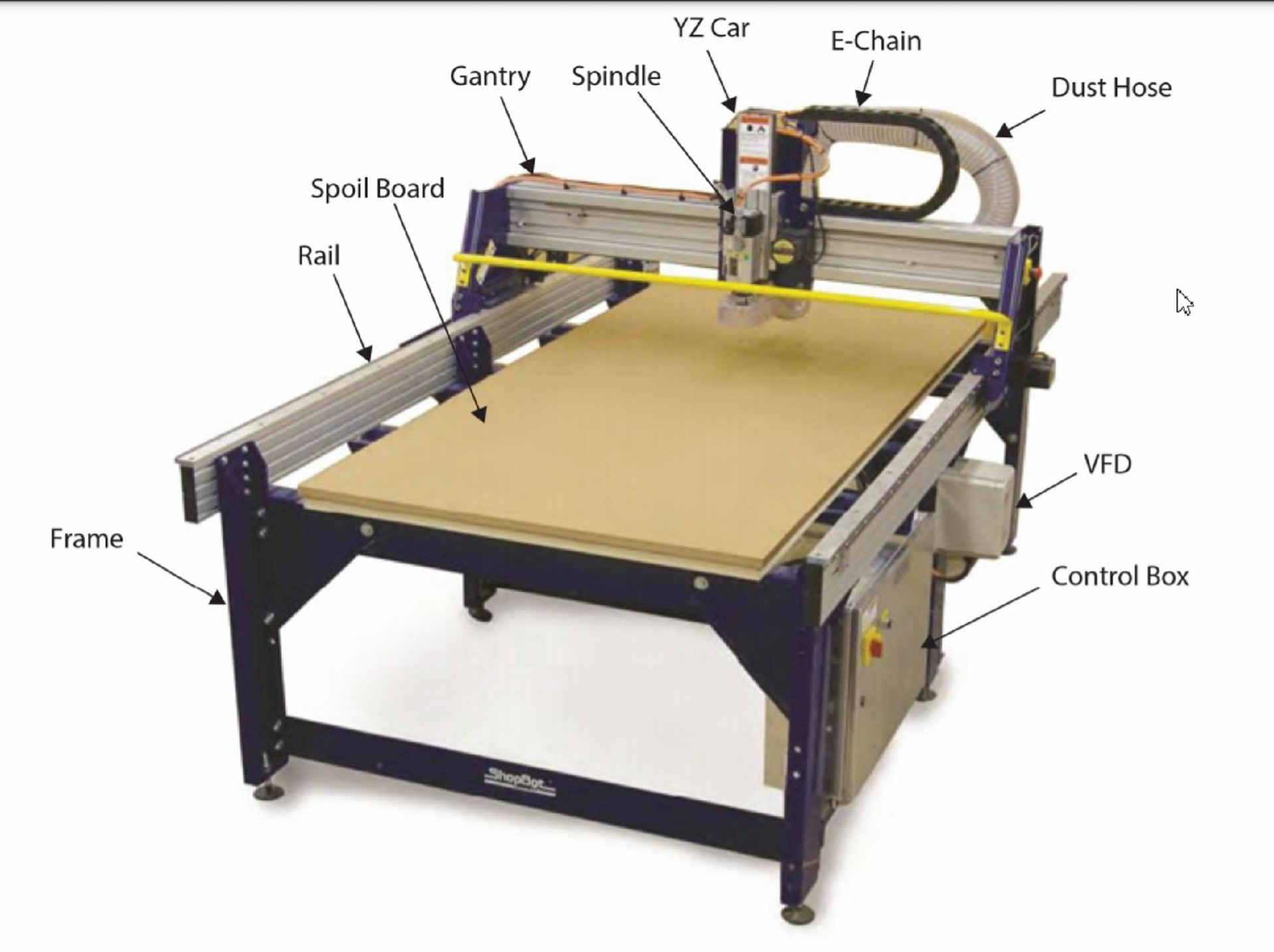
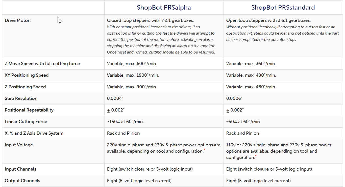
They have ShopBot PRSalpha. It is a 3 axis CNC router machine which is substractive in nature. Using advanced technology for CNC cutting, drilling, carving and machining, the PRSalpha series tools deliver rapid transit speeds of 1800 inches per minute and cutting speeds of up to 600 inches per minute.
We had been introduced to the machine and its various parts through online session by Apeksha Bochare Madam. We tried generating toolpath for our random designs.
Parts and Specification of ShopBot PRSalpha:
| Model | Cut / Movement Area* | Footprint (L x W x H) |
|---|---|---|
| PRSalpha 96-48 | 105” x 49” x 8” | 120” x 79” x 67” |
Application of ShopBot PRSalpha:
- Cabinet Making
- Theaters and Museums
- Sign Making
- Furniture
Important Parameters in Computer Controlled Machining using ShopBot are Feed rate, Stepover, Plunge rate and Spindle speed:
- Spindle Speed - rotational speed of the cutting tool in revolutions per min
- Feed Rate - Surface speed at the center of the rotating tool
- Plunge rate - It is also known as stepdown, it is the distance in the z direction per pass that a cutting tool is plunged into the material
- Step Over - the maximum distance in the x/y direction that a cutting tool will engage with uncut material
- The formula for calculating feed rate is,
FeedRate = ChipLoad x CutterDiameter x NumberOfFlutes x SpindleSpeed
Where: - Chipload is the amount of material cut per tooth (feed per tooth)
- Number of flutes and cutter diameter are determined by your tool
- Cutter diameter is the diameter of the tool
- Depending on the size of your bit, the chipload for plywood is between 0.005 inches 0.01 inches per tooth. For small bits below 1/8 inch start with 0.005 and increase from it there. For bits 1/4 inch and larger you will probably not break anything starting out at 0.01.
The settings for the tool used by us in Shopbot are as follows:
- Tool Diameter: 0.25in
- Pass Depth: 0.27in
- Stepover: 0.1in (40%)
- Spindle Speed: 12000 r.p.m
- Feed Rate: 27mm/s
- Plunge Rate: 3.0mm/s
Shopbot usually works with a combination of two different softwares.
- One to define the path to cut (Gcode maker)
- Second to control the tool and follow the path (machine driver)
- To make the gcode of path we used Partworks (2D).
- There are other softwares like mastercam, vcarve etc. but partworks is recommended by shopbot.
For wood, general rule of thumb is to always make pass depth 1/2 the diameter of the tool. So in this case of a 0.25″ (1/4″) end mill, The pass depth should be to 0.125″ (1/8″). Depending on the wood you are cutting, you might be able to increase this. Pine, for example, cuts well at 0.25″ (1/4″) deep whereas Oak works well at 0.125″ (1/8″).
NOTE: As a general rule, One should not exceed the diameter of the tool as it can put undo stress on the machine, spindle and the tool. The only exceptions to this would be for very light material like foam or Balsa wood.
We know this, still you can see that the Pass depth is more than the tool diameter, We tried to convince the administration at COEP, but they were adamant on their parameters. Being their machine, we had to use these values.
Due to the Covid Pandemic, we had remotely accessed the machine and generated toolpath using AnyDesk Website. The software used for toolpath generation is Partworks.
After the Parametric design of the Object (Stool), the scaled down version was printed on the Numac Hitech machine. Art Cam Pro and NcStudio Softwares were used for the toolpath generation.
Numac Hitech Wood Drilling Machine:
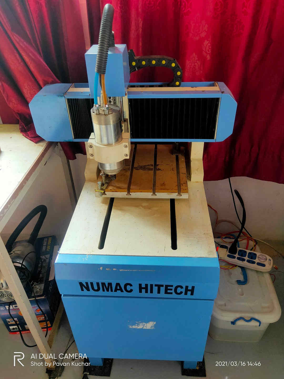
Numac Hitech
Details of Group Assignment could be found here.
2. Individual assignment:
Make (design+mill+assemble) something big (~meter-scale)
The flow of this Assignment is as follows:
- Designing Object parametrically
- Assembling the Parts of Object
- Creating the .dxf file (2D Vector file) for Milling
- Generating the Toolpath for CNC Milling
- Milling by ShopBot machine
- Assembling the Parts
- Hero Shot of the Object
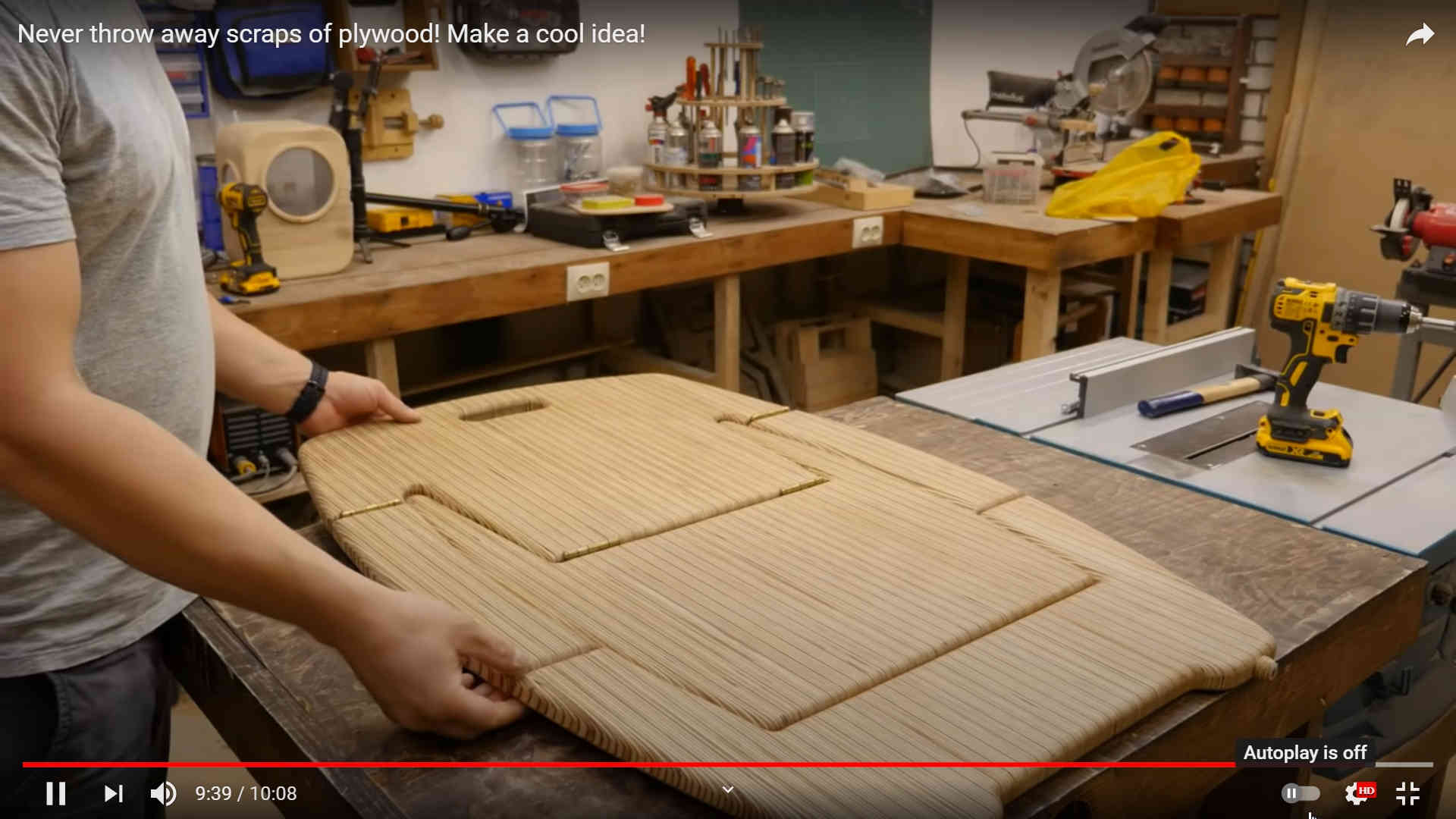
To make something BIG, I went to search on Google and YouTube for certain ideas as I have never worked with Wood. I also referred to the designs of few previous year FabLab students. I realized that the designs I liked were to complex and I may not be able to design them in freeCAD or Rhino-6. S, I restricted myself with a much simpler but effective design of Stool that could be used anywhere in Vigyan Ashram. I wanted to make a two step table or may be a ladder.
 Idea 1
Idea 2 inspired by FabLab 20 Kochi's Anooj Jacob.
Designing Object parametrically:
We were told to make a Parametric design of the object which would allow us to change the dimensions on time if the size and width of the Plywood changes (The width of the Plywood changes due to Humidity). Also, if we are denied access to the Lab of ShopBot in COE,Pune, we may be able to mill the scaled down version of our design in our FabLab-0 with Numac Hitech.
 Trial 1 - Compact Design of the Stool
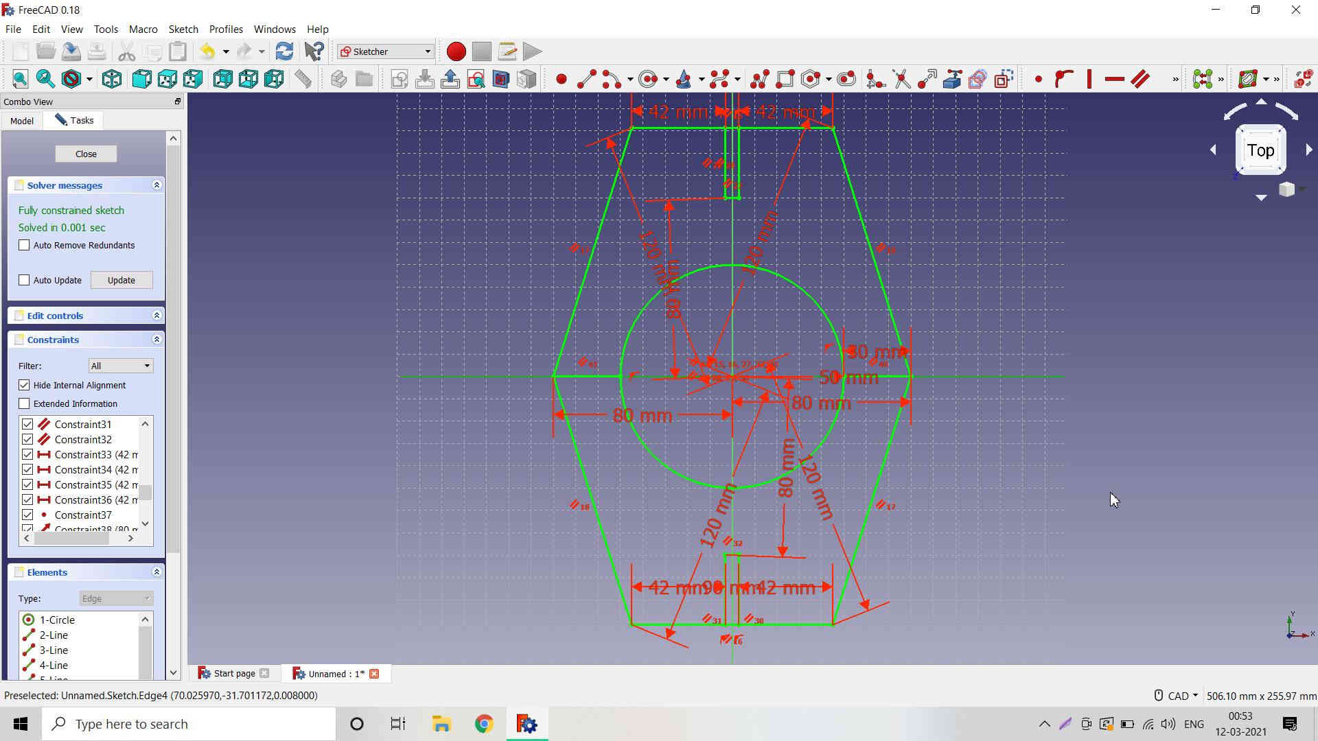
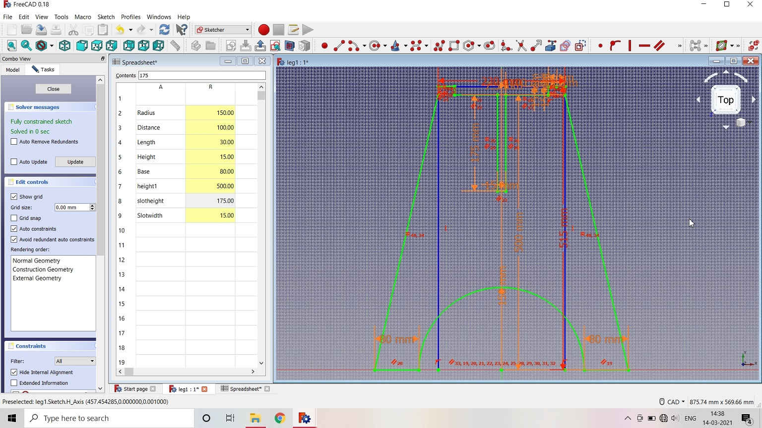
The very first design I made was parametric but I made it in the Sketcher workbench. When I applied Pad and created a Body, it was not created as I have thought of it. Also, the slots were not matching or complimentary to each other.
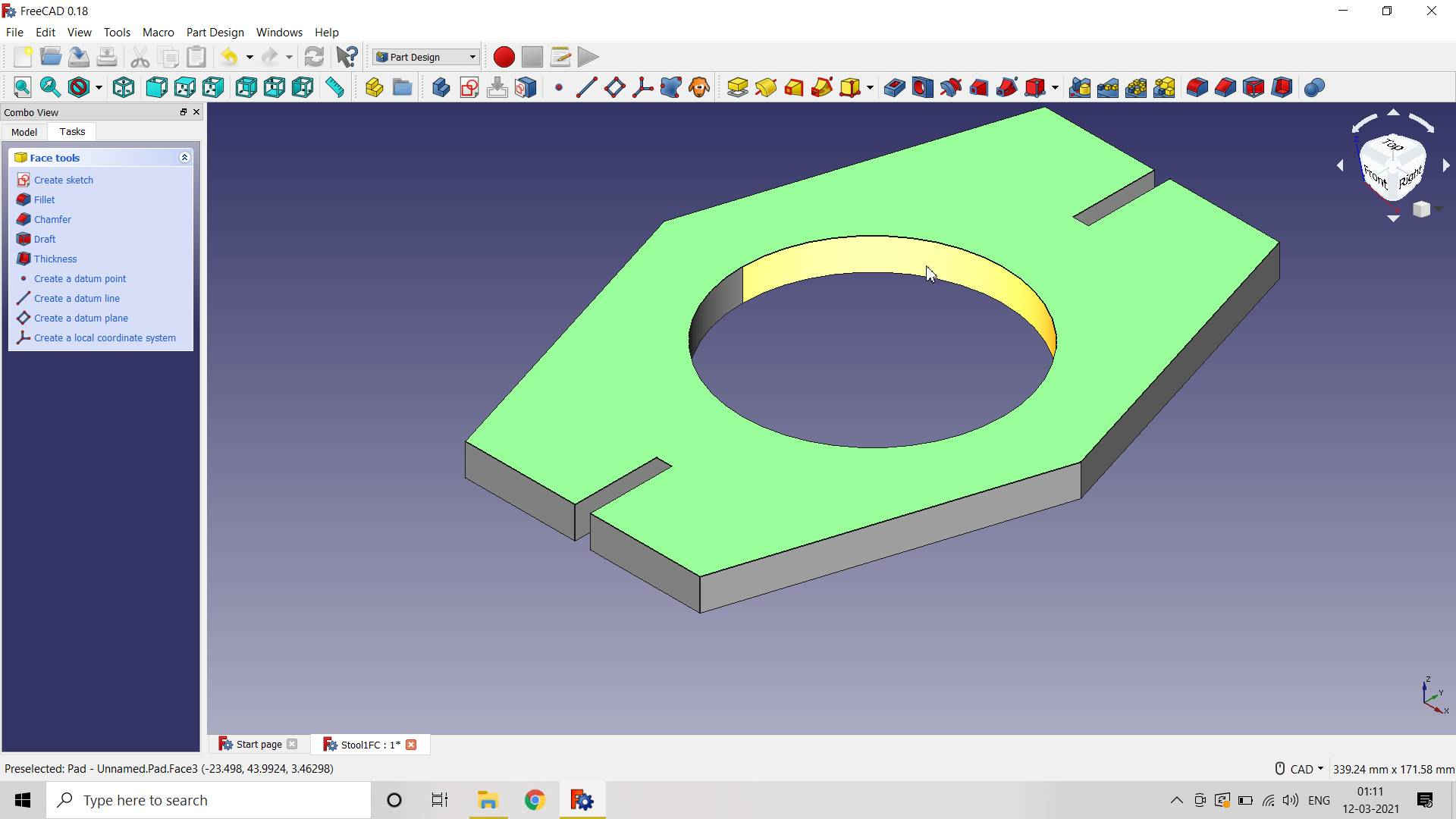 Body created by Padding Up the Object
I once again designed the parts seperately in Part Design. Then I created the body and corrected the slots of the object. The resultant parts turned out as I have thought of.
 Designing Leg 1 of Stool
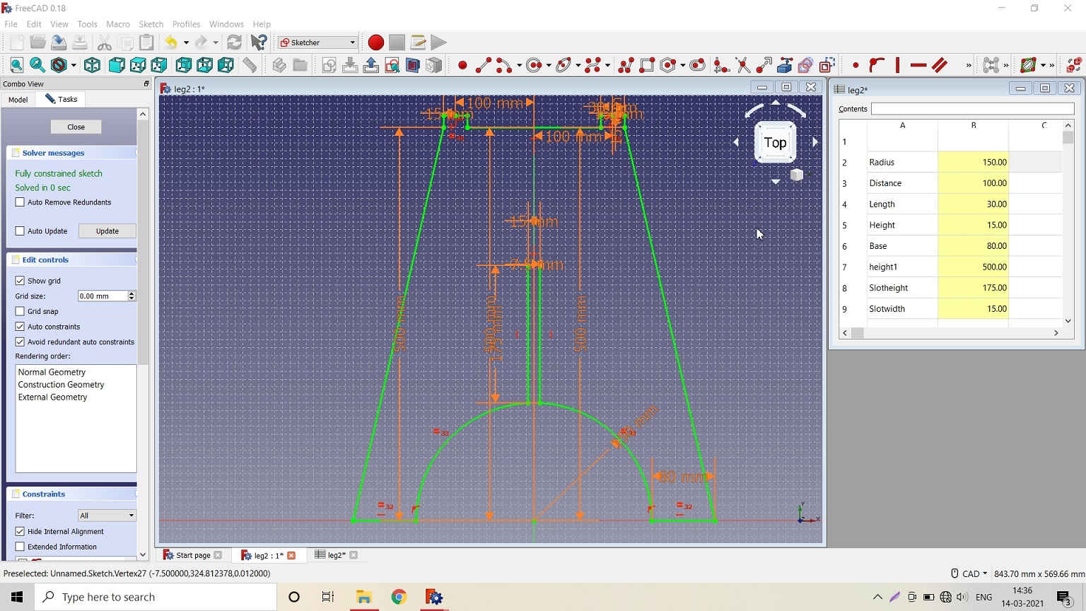
 Designing Leg 2 of Stool
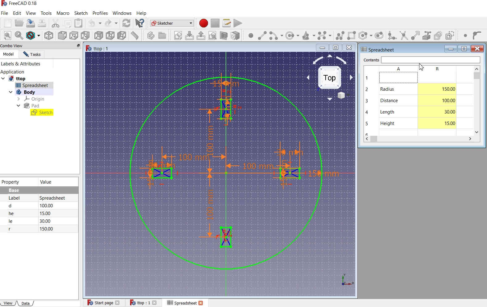 Designing the Table Top of Stool
I padded the parts and created the body out of it.
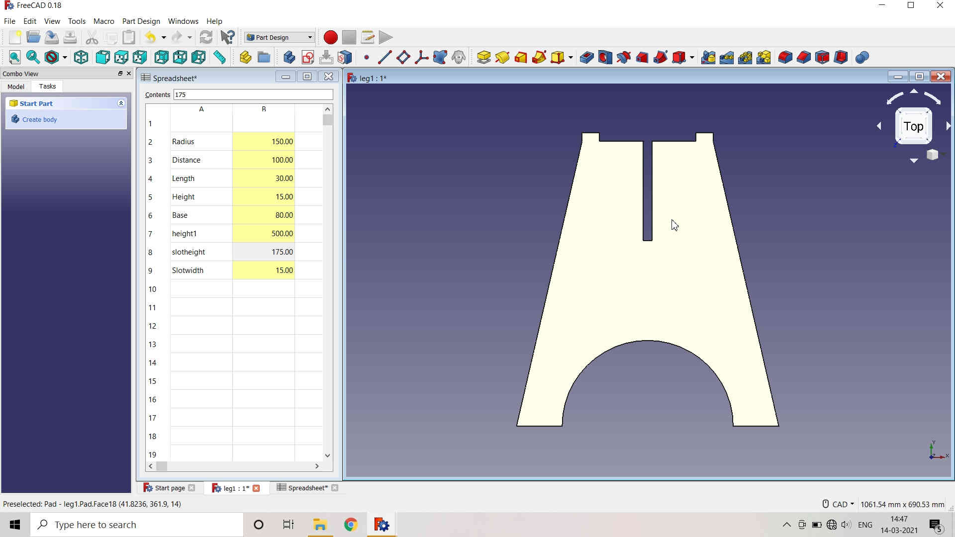 Padding Up and Body created for the Legs of Stool
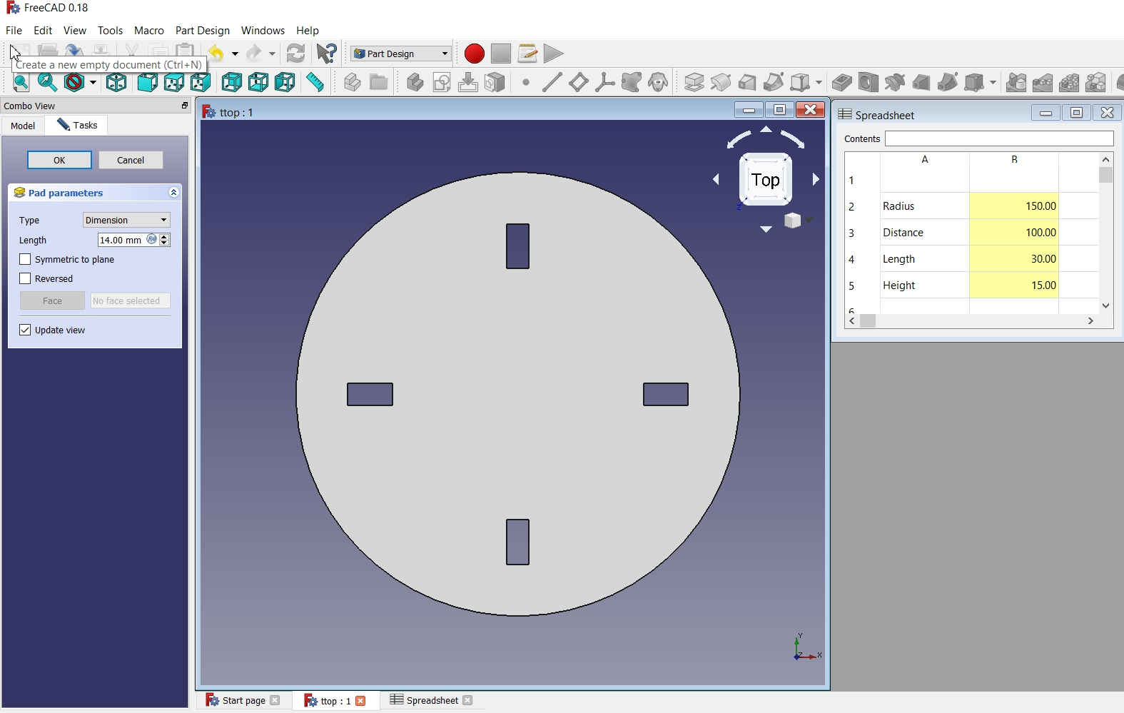 Padding Up and Body created for the Top of Stool
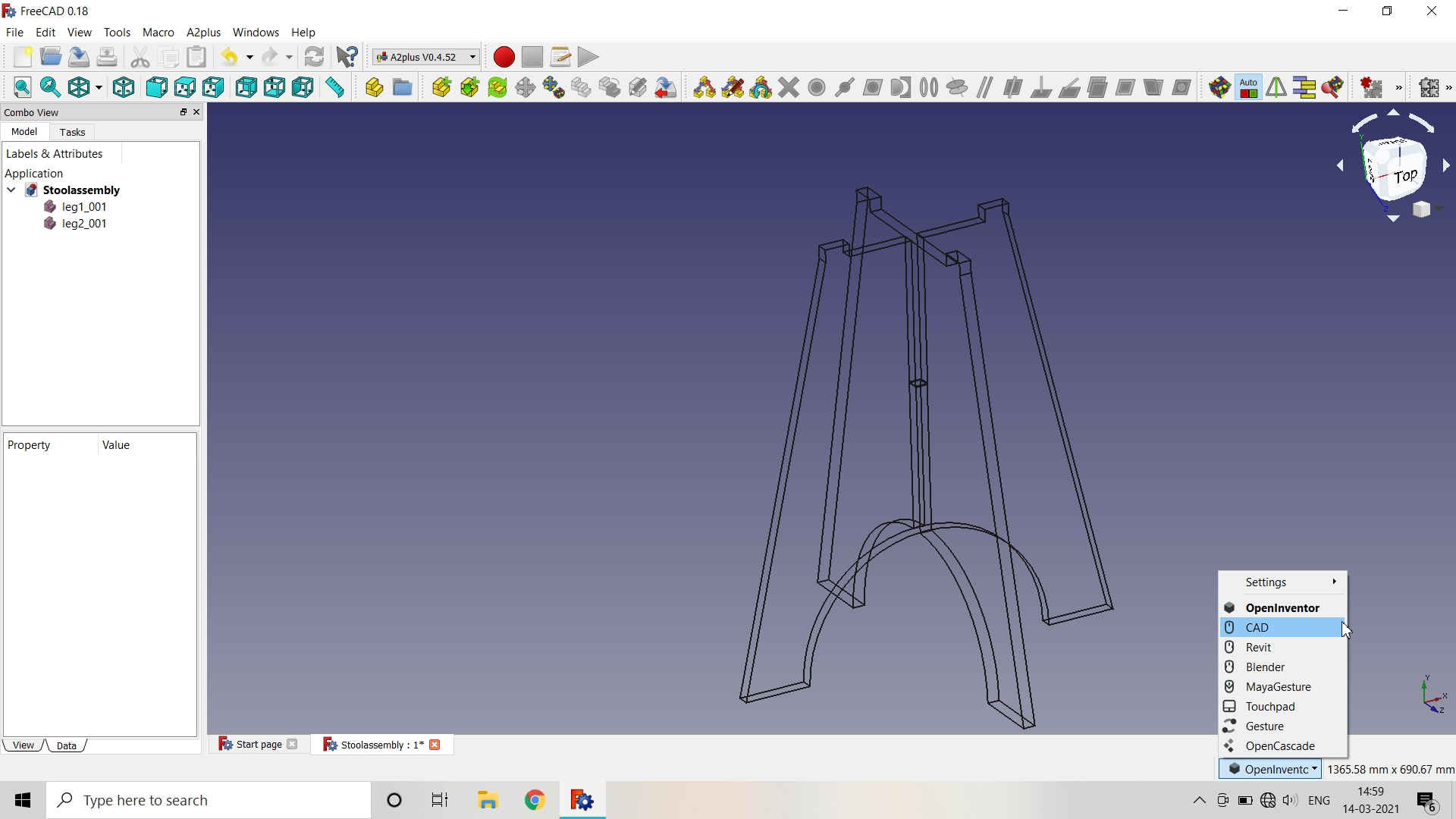
Assembling the Parts in A2plus Workbench:
The Assembly workbench was not availavle in the freeCAD as The A2plus workbench is an external workbench to assemble different parts in FreeCAD. The A2plus workbench is an addon to FreeCAD. It can easily be installed via the FreeCAD AddonManager from the Tools → Addon Manager menu. The A2plus code is hosted and developed on GitHub and can also be installed manually by copying it into FreeCAD's Mod directory.
After Installing the A2plus workbench in freeCAD, I assembled the parts. Reference Link
First of all, switch to the A2plus toolbar in FreeCAD. To create an assembly create a new file in FreeCAD. At first this file needs to be saved. It is recommended (but not necessary) to save it in the same folder of the parts you want to assemble.
Now parts can be added to the assembly by using the toolbar button  A2p ImportPart or A2p ShapeReference. The button A2p ImportPart adds all bodies in the selected file as a single part. When using the button A2p ShapeReference you can choose what part from a file should be imported as part. This way one can import a sketch to assemble further parts using the sketch to determine the part positions.
 |
 |
|---|
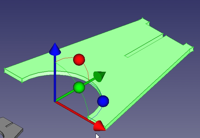
After Importing the parts, place them in the bed area and then we can move them with the help of Move  button.
 |
 |
 |
|---|
You may move the parts in various directions and along the axes by usingthe arrows and the Red, Blue or Green colored buttons.
Once the parts are arranged with each other, you may fine tune and better align the edges with the help of Alignment (Axial Constraint) button. An activity dialogue box pops up where you have to feed the desired changes and click OK.
.jpg) |
 |
|---|
 |
 |  |
|---|
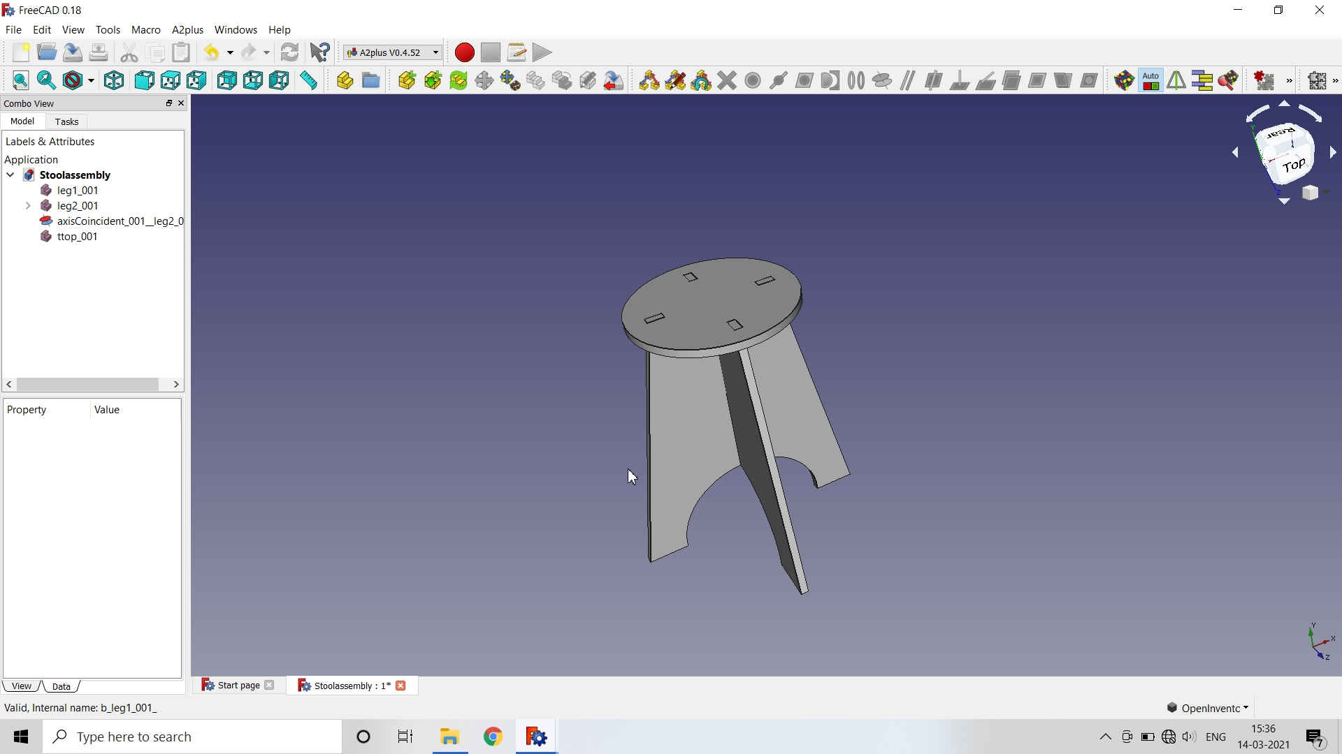 Assembly of (Legs and Top) Stool
Creating the .dxf file (2D Vector file) for Milling (using Drafts Workbench):
For generating Toolpath, we had to save the design file in the .dxf format. I created the file for milling using the Drafts Workbench in the freeCAD.
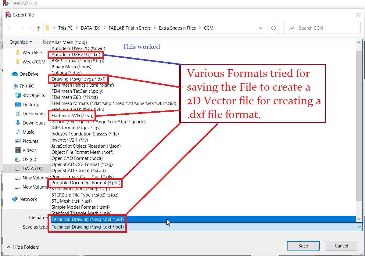
- Earlier, I tried to export the file but the dialogue box popped up saying that the file format is not supported for exporting.
- Then, I tried exporting the file as .pdf file but again it was exported as 3D object.
- Then, I tried saving it in the flattened .svg file format. Here the legs of the Stool were converted and exported as intended BUT the top portion with grooves was exported without grooves as a flat surface.
- Atlast, I saved the file as Autodesk 2D file and Voila it was done.
- I then imported the files in the RD Works software and arranged them on the Bed Area.
 Leg 1 Leg 1 |
 Leg 2 Leg 2 |
 Top Top |
|---|
Various file formats tried to save the freeCAD file in 2D vector files were:
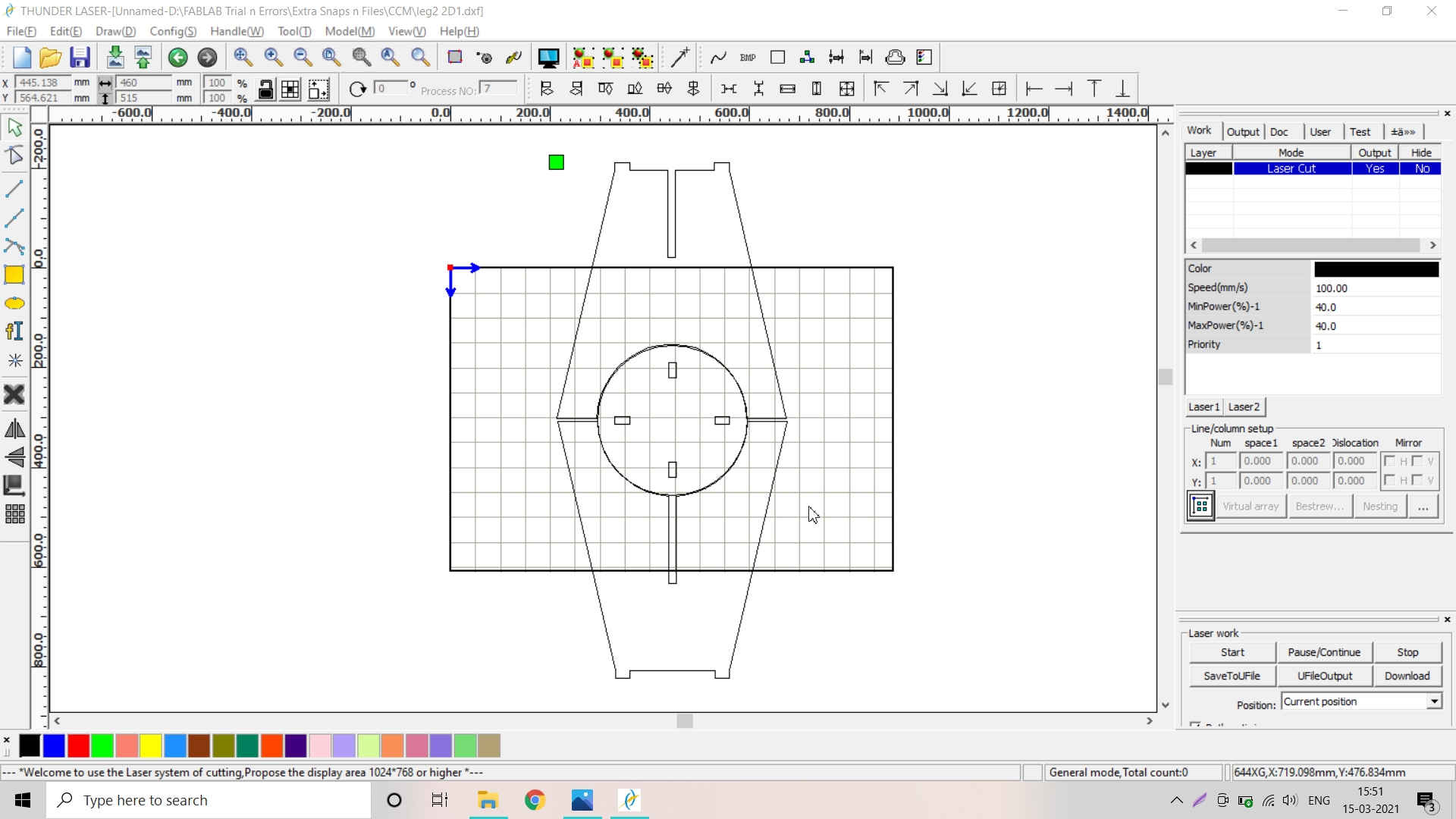 Creating the .rld file in RD Works
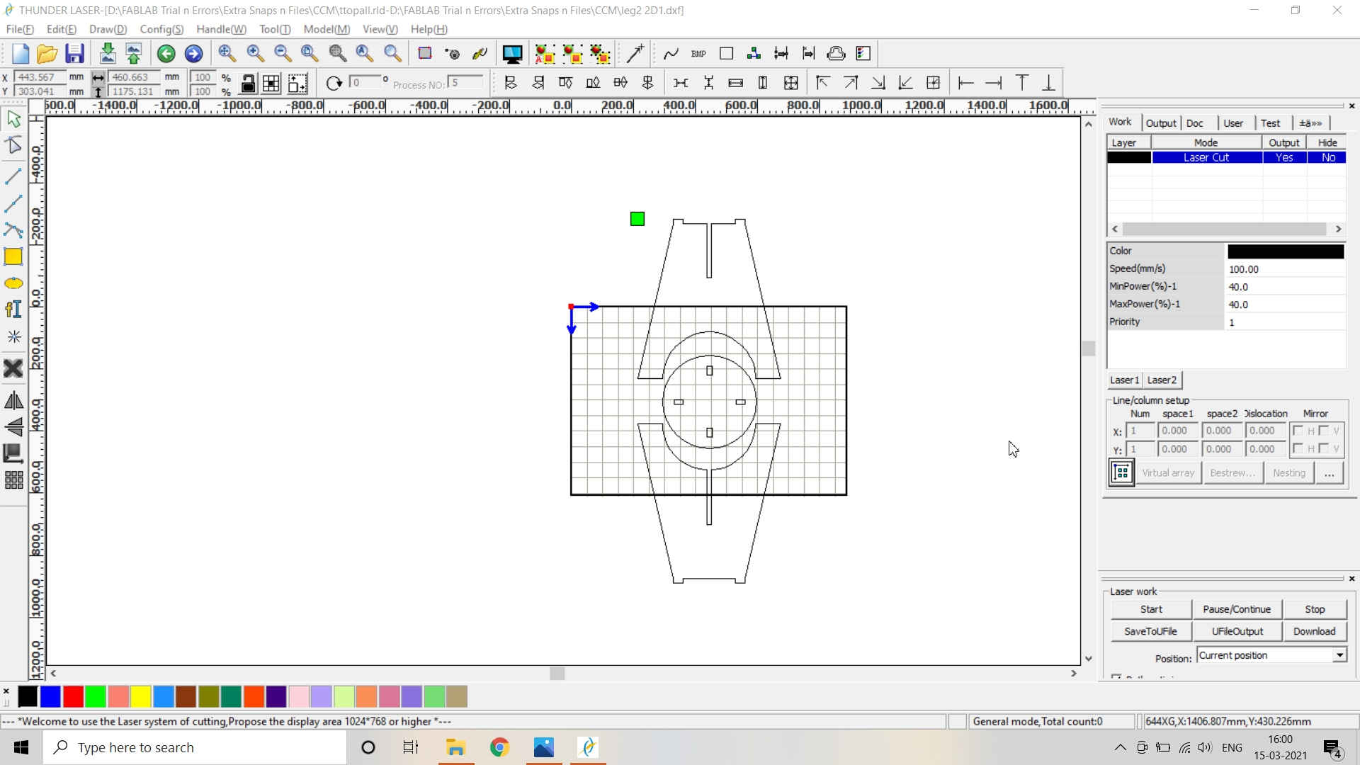 Rearranging the Objects on the Bed for Creating the .rld file in RD Works
About PartWorks (Software of Toolpath generation for ShopBot PRSalpha:)
PartWorks has been developed specifically to open decorative designs and calculate perfect 3D V-Carve / 3D Engrave toolpaths as quickly and easily as possible. The general work flow logic to apply to most jobs is explained below. Reference link.
- Open or Import the vector design
- Select the regions to VCarve or machine
- Specify the tool details and calculate toolpaths
- Preview the job in any material
- Save the CNC code
Toolpath Generation:
Due to Covid, we have not physically handled the ShopBot milling machine. We have generated the toolpath using Anydesk Software. Following are the stepd followed by me for the toolpath generation.
AnyDesk Software Installation:
- Install the Anydesk Software in the Laptop.
- Send the request to access and connect the other Computer terminal.
- If the request is accepted, you may access the terminal.
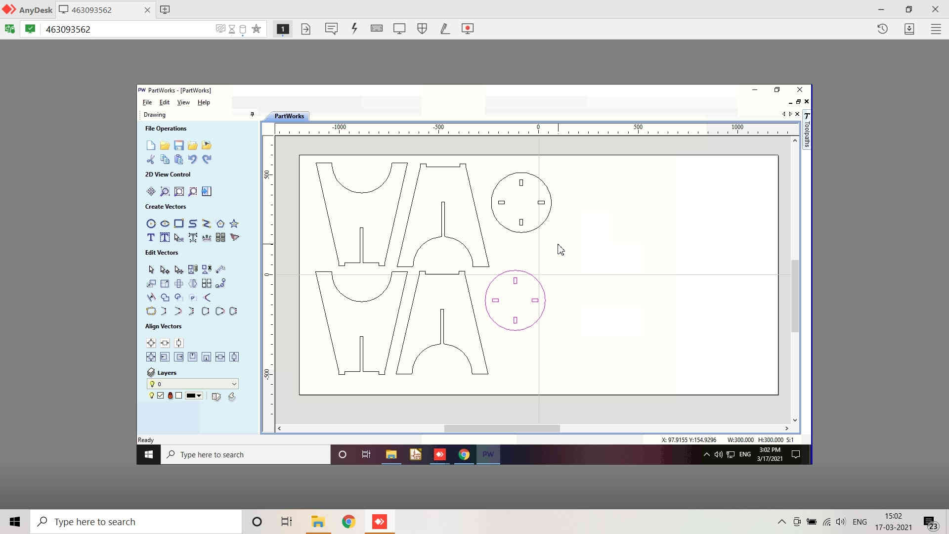
Toolpath Generation using Partworks:
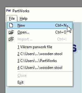
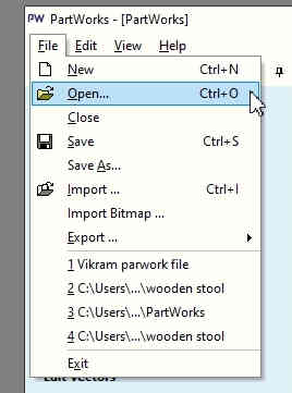
- Open the Partworks software.
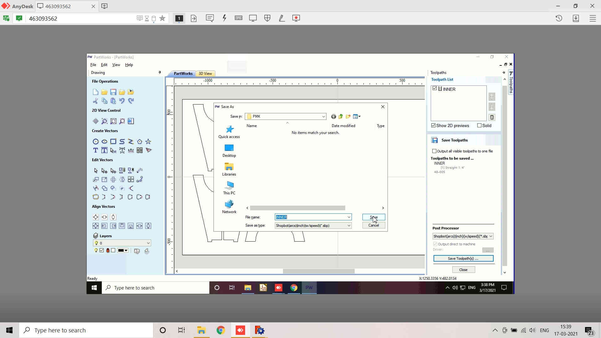
- Create a New File and save it in your name or desired file name. I saved it as pmk(.crv) VCarve file in the Folder created on the desktop as CCMFiles and a subfolder PMK.
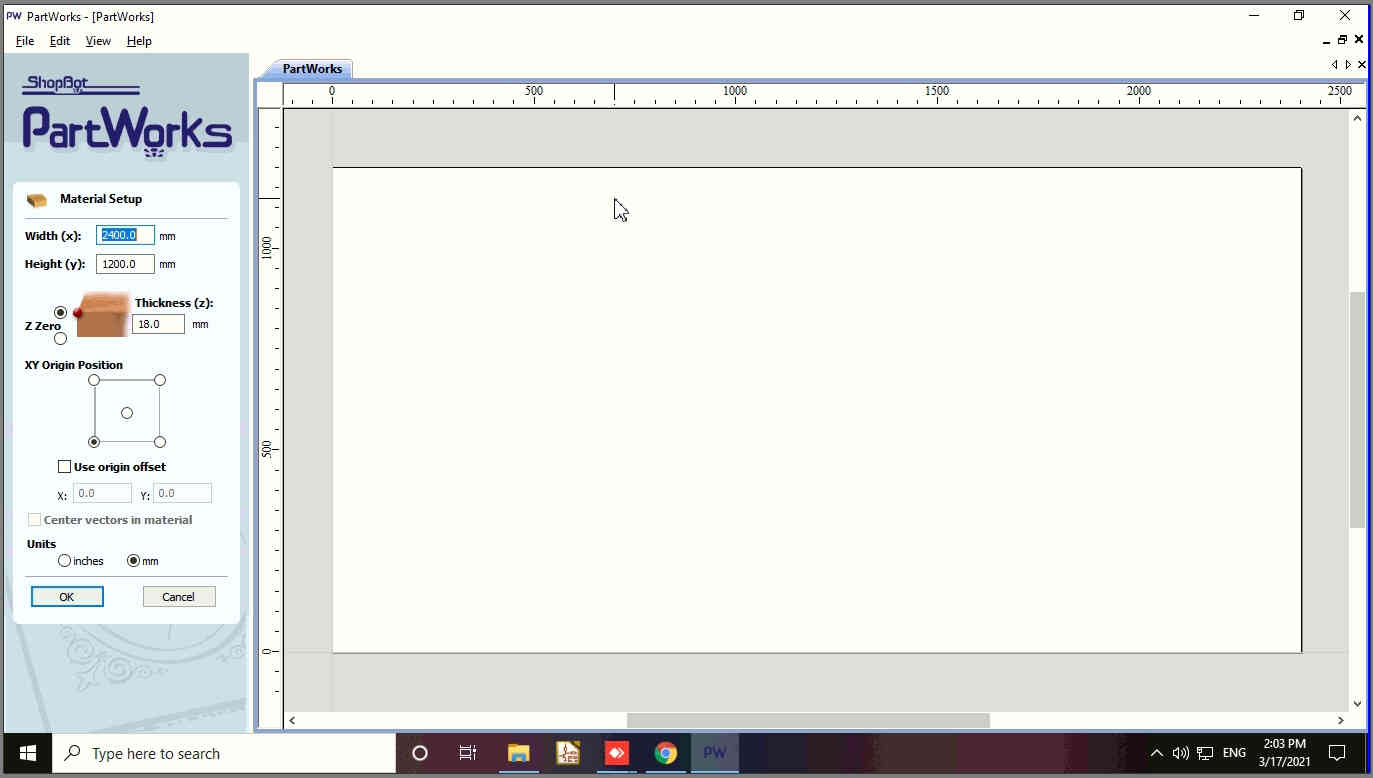
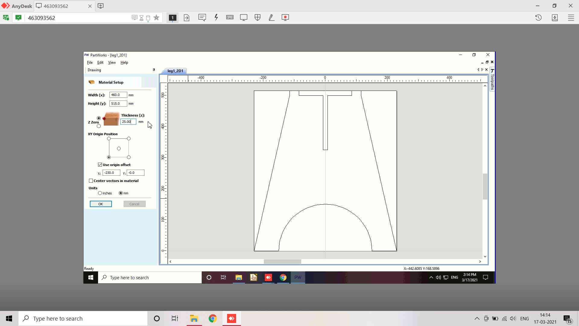
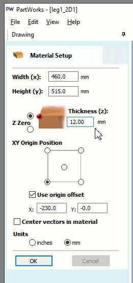
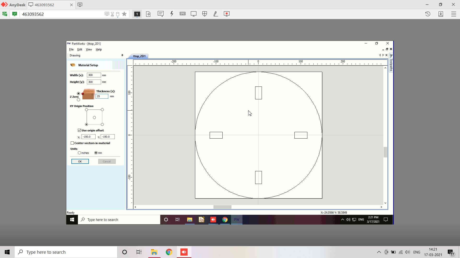
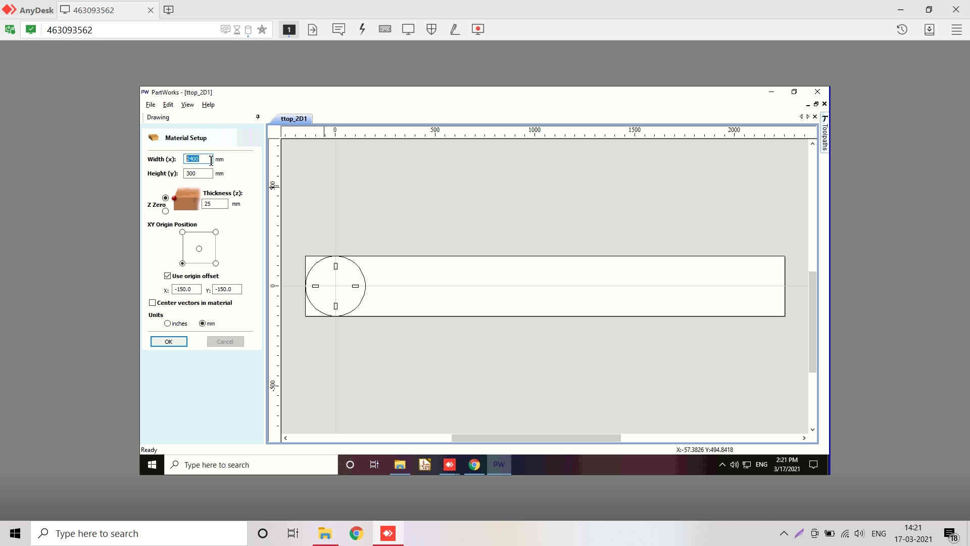
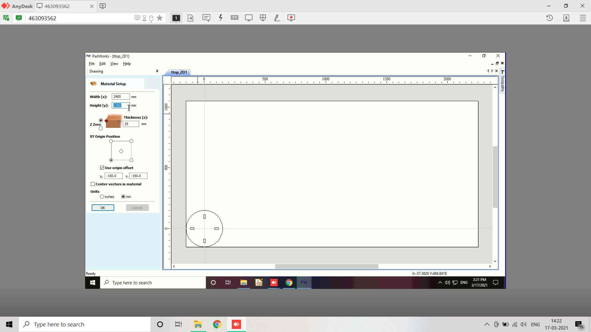
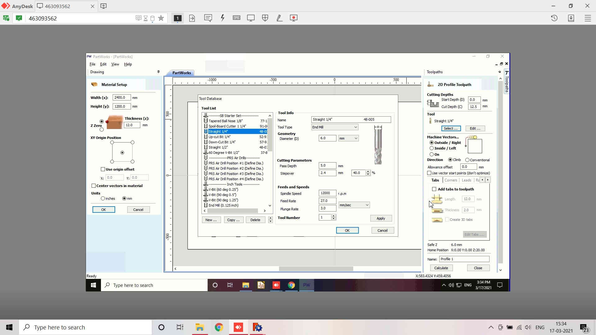
- This will open a Material Setup window. Set the Width(X) and Height(Y) of the material along with Thickness(Z) of the material that you will be using. I have set the bed size as 2400 x 1200 mm and the material (Plywood of 12 mm in my case) thickness.
- You may also change the origin position of the mill. I have set it in the bottom left corner of the display from where I may access the machine.
- You may change the size in millimeters or inches as per your preference and design specifications.
- After this, a window for the Drawing settings is opened where you have to nest the parts of your design for milling.
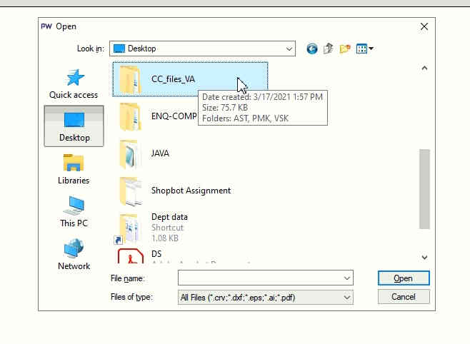
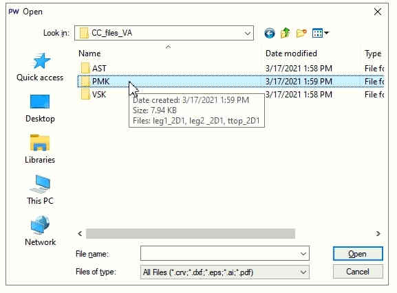
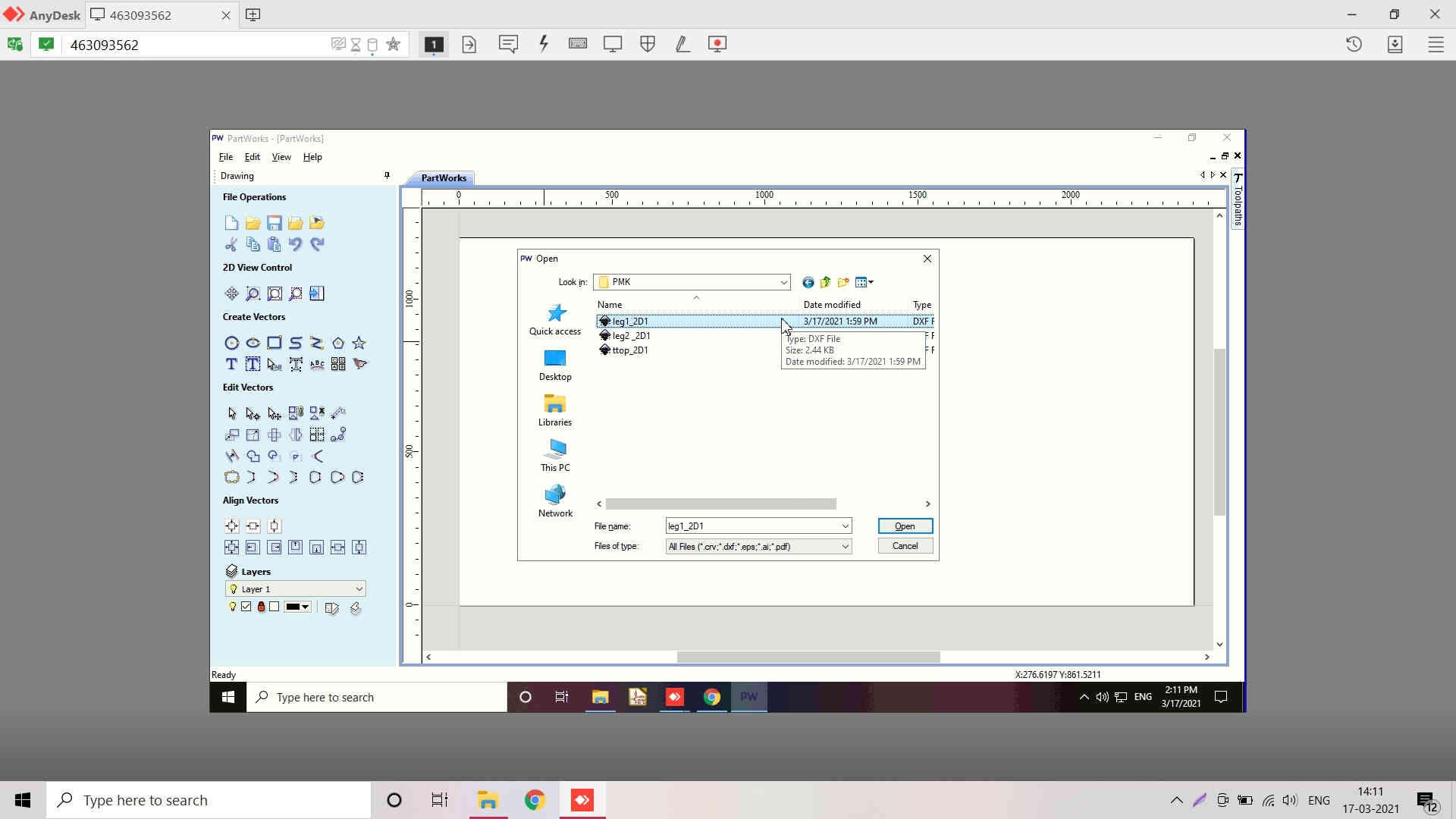
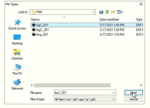
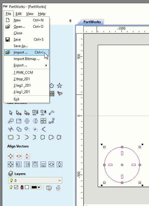
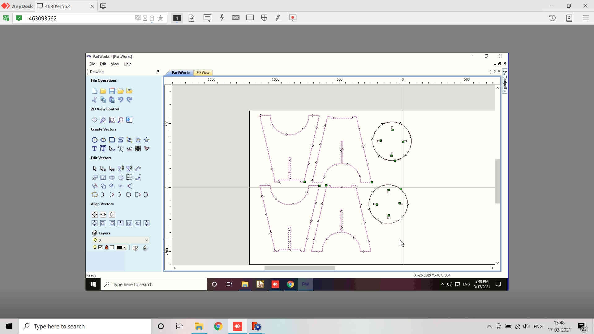
- Here, I made a mistake of opening the file instead of Importing the .dxf design files.
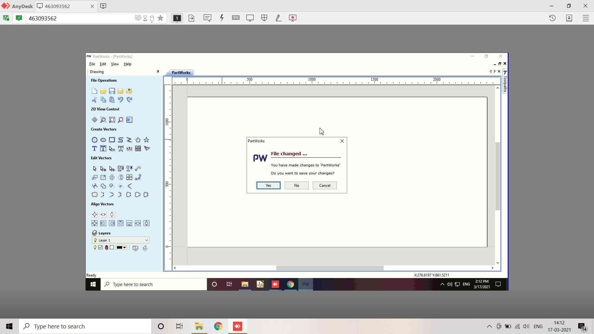
- This is how a window popped up stating that I have made certain changes to the Partworks and would I like to save it. I clicked on Yes.
- Because of this, the part that I opened spanned in the whole window and the name of the file also changed form pmk to leg1_2d1
- I discarded the file and started with new file. but again I opened the file instaead of importing it. I thought lets see what happens. I then made changes in the Drawing section by changing the XY Origin offset and reducing the X and Y positions / coordinates.
- This is how the part was nested in the bed area.
- After doing all this and nothing working out, I realized the mistake I was making.
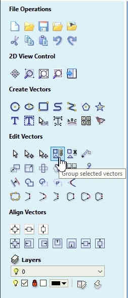
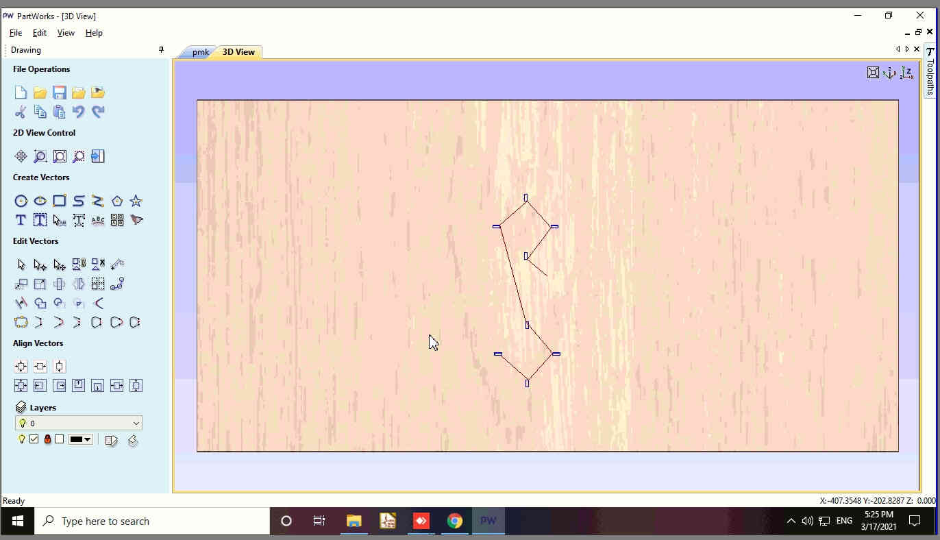
- The various tools available in the Partworks for the drwawing and nesting the parts of the designed object are :
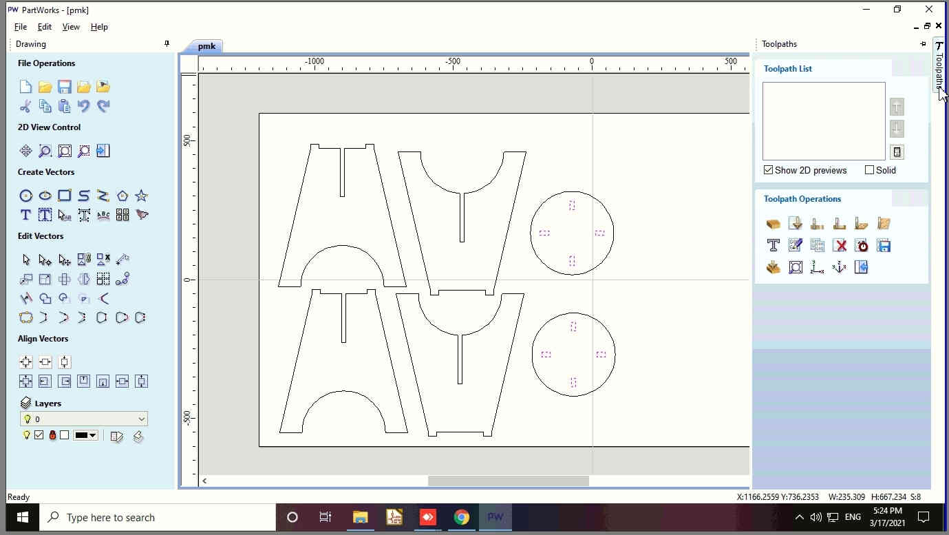
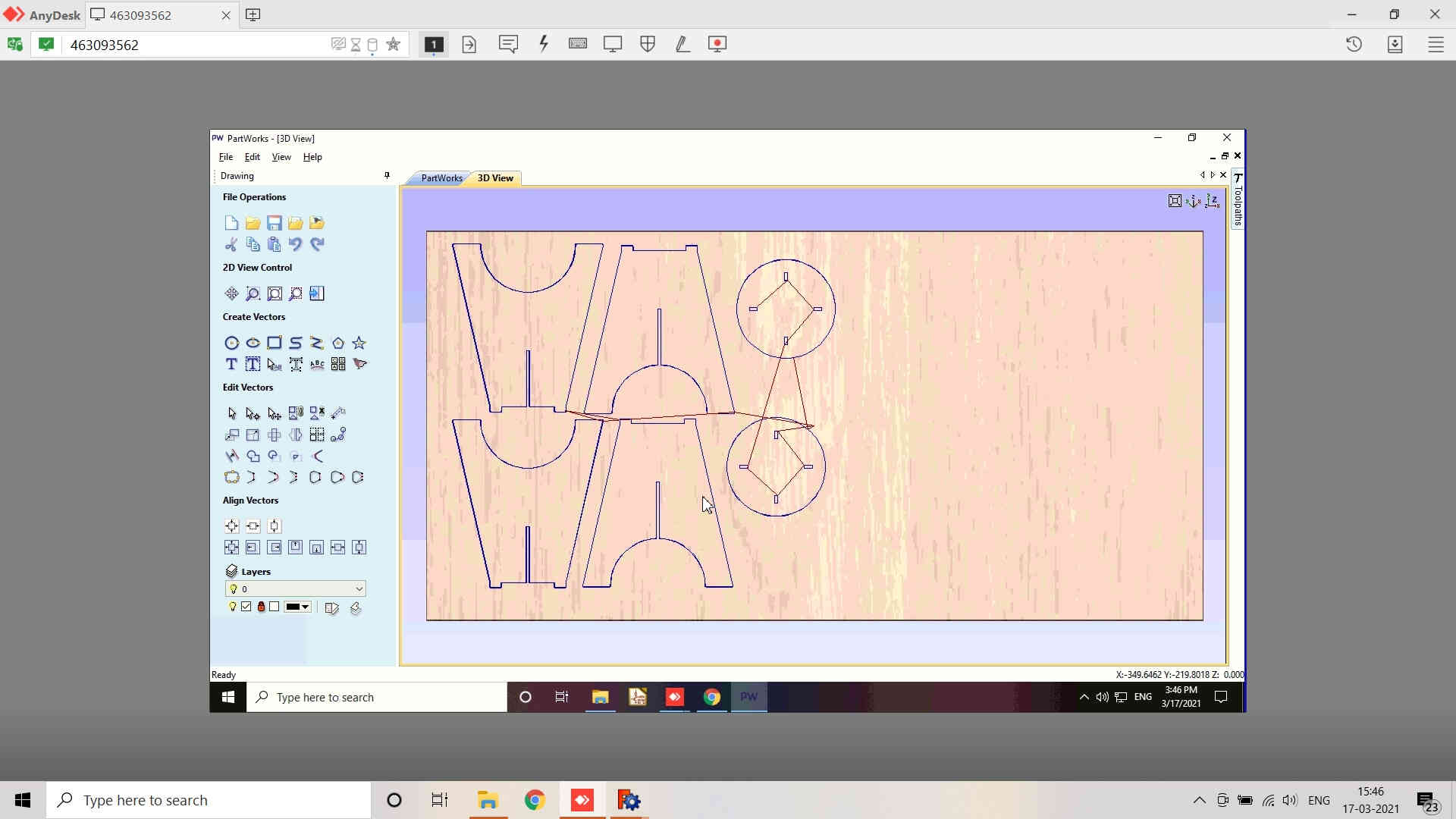
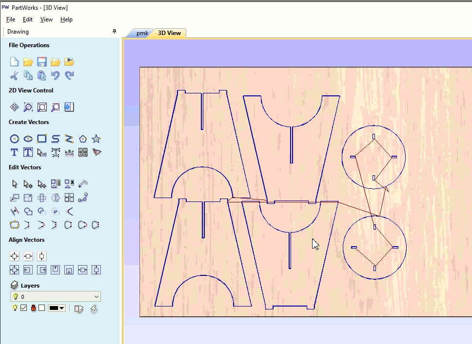
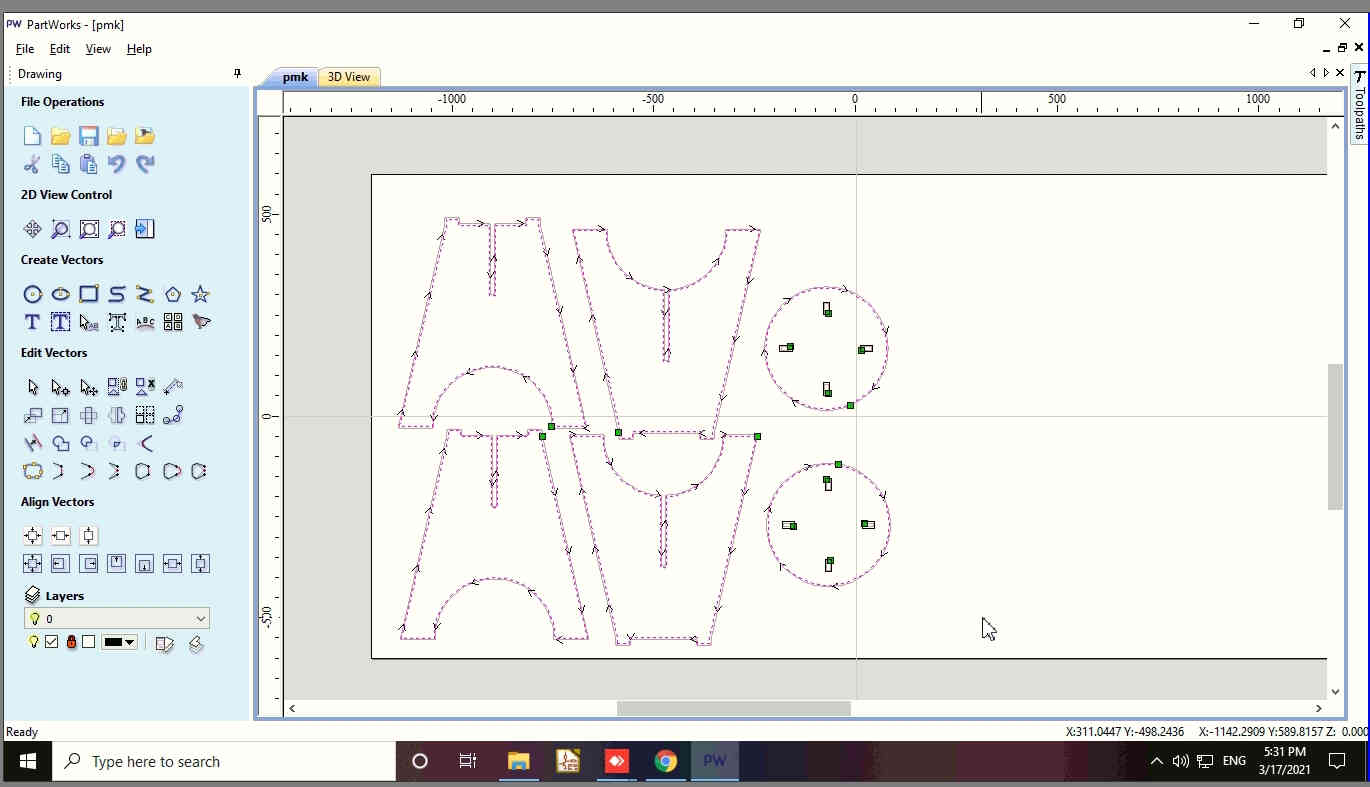
- After realizing the mistake, I imported the .dxf files from the folder and then the parts were nested in the bed areas according to their size.
- I successfully imported all the parts in the bed area of the Partworks and aligned them to optimally utilize the space available.
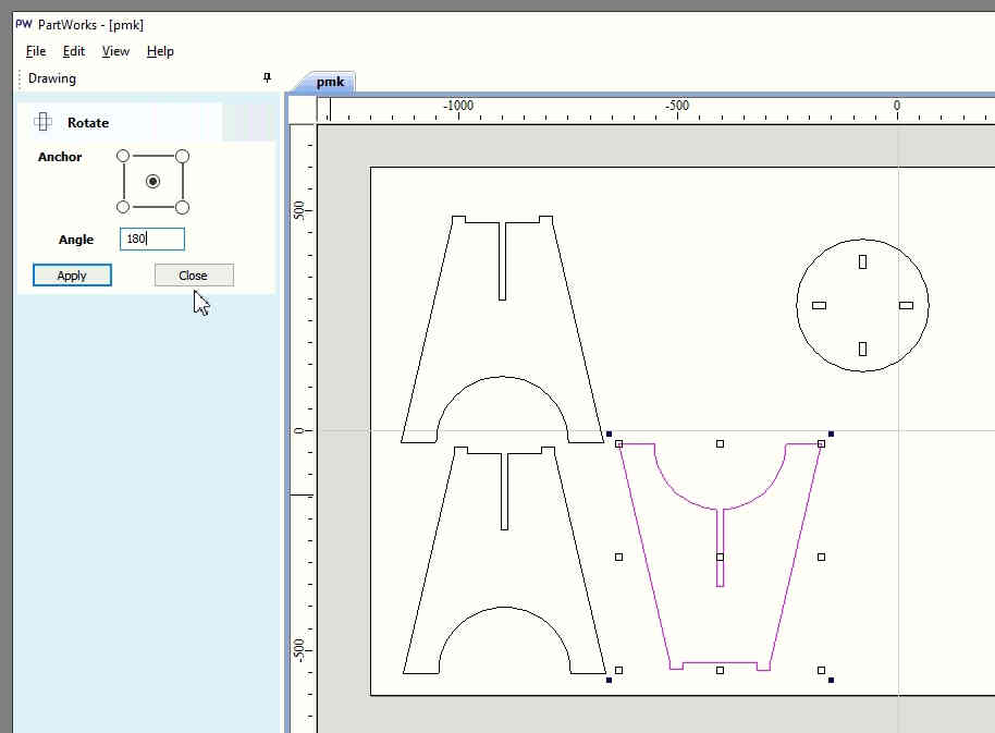
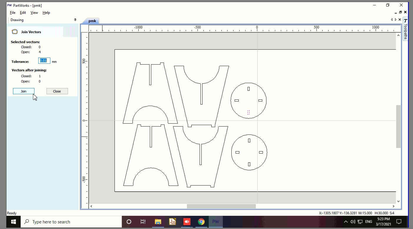
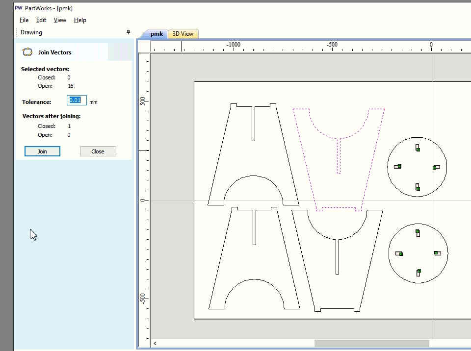
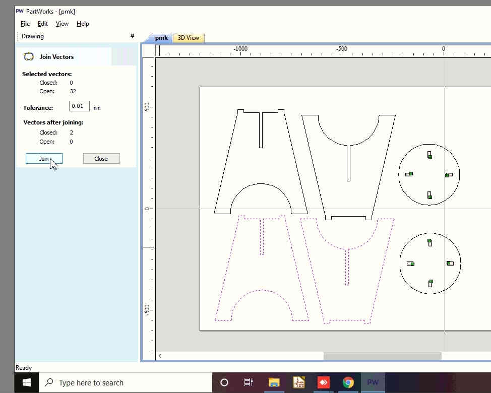
- Arrange all the objects in the Cutting area of Partworks by using the Move and rotate tools. I have respectively used the Move, Join Vectors, Group, Ungroup and Rotate tool to move, join, group, ungroup and flip the legs of the stool vertically.
- These steps are imporatant for creating a toolpath.
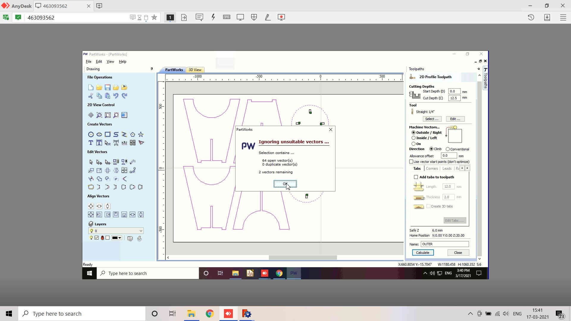
- Select any object and if it is displayed with connected lines then we may say that it is a vector but if the object is displayed by continuous line then it may not be a vector object and may have open / broken vectors/joints.
- For this, select the object, check whether its open or closed. If open vectors, then join the vectors by using the Join Vectors tool.
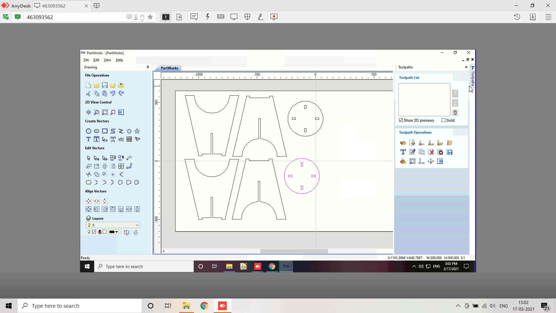
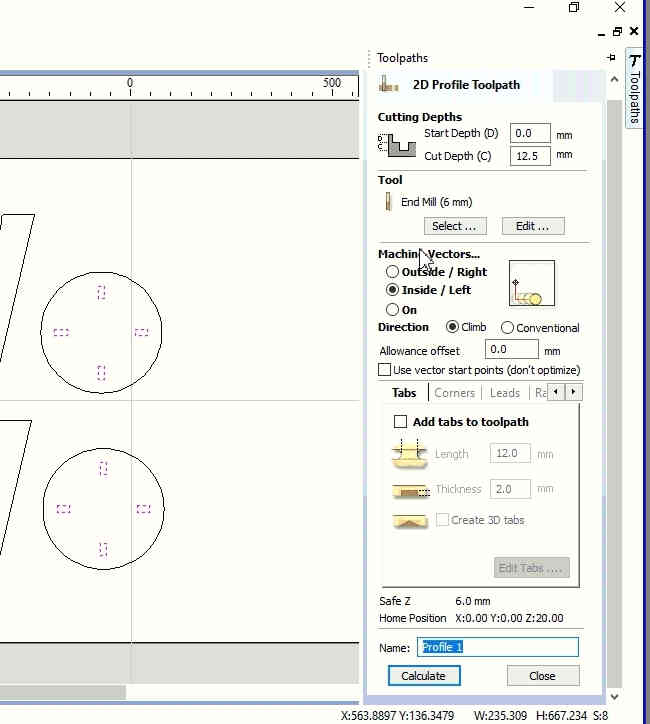
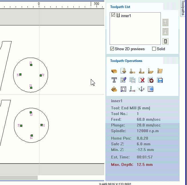
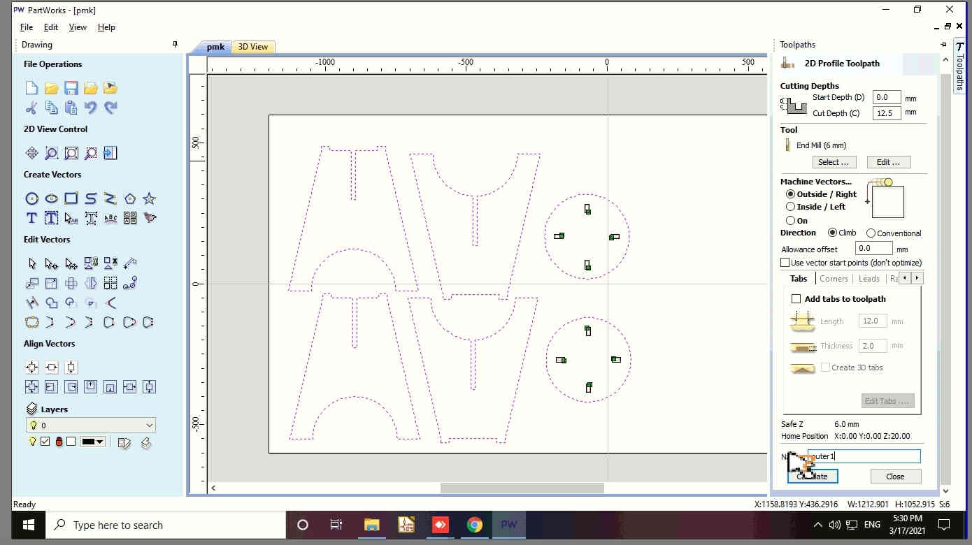
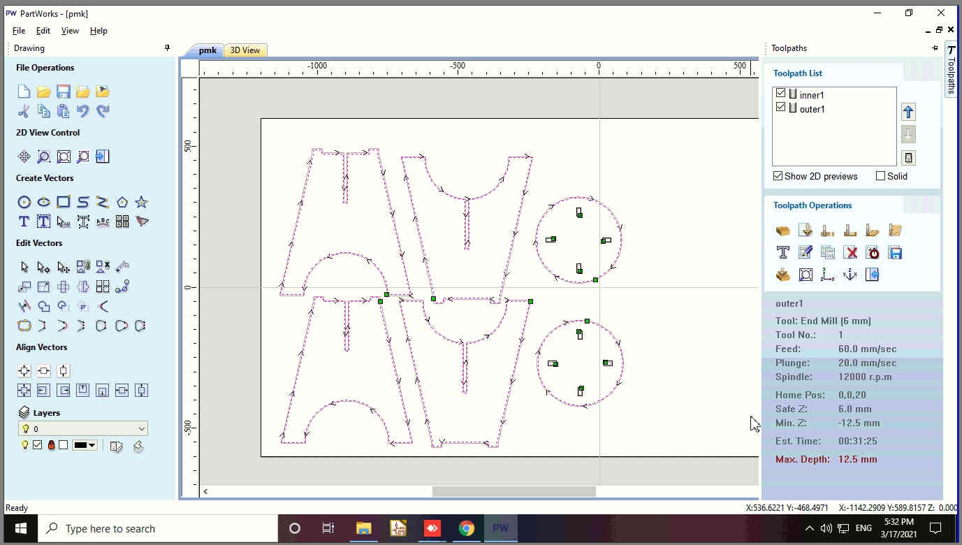
- Toolpath is on the top right position of the screen. Selecting it would open a window from where you may generate toolpath for your job.
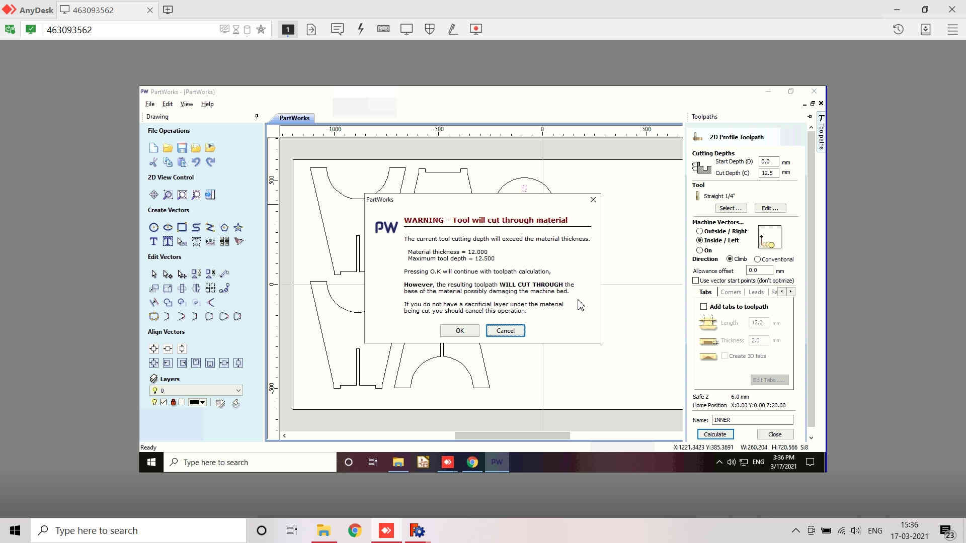
- Cutting Depths: includes Start Depth (D), Cut Depth (C). I have kept the start depth as 0.0 mm and the Cut depth as 12.5 mm. (Note that the Cut depth is always greater than the Material size; provided the sacrificial layer is available.)
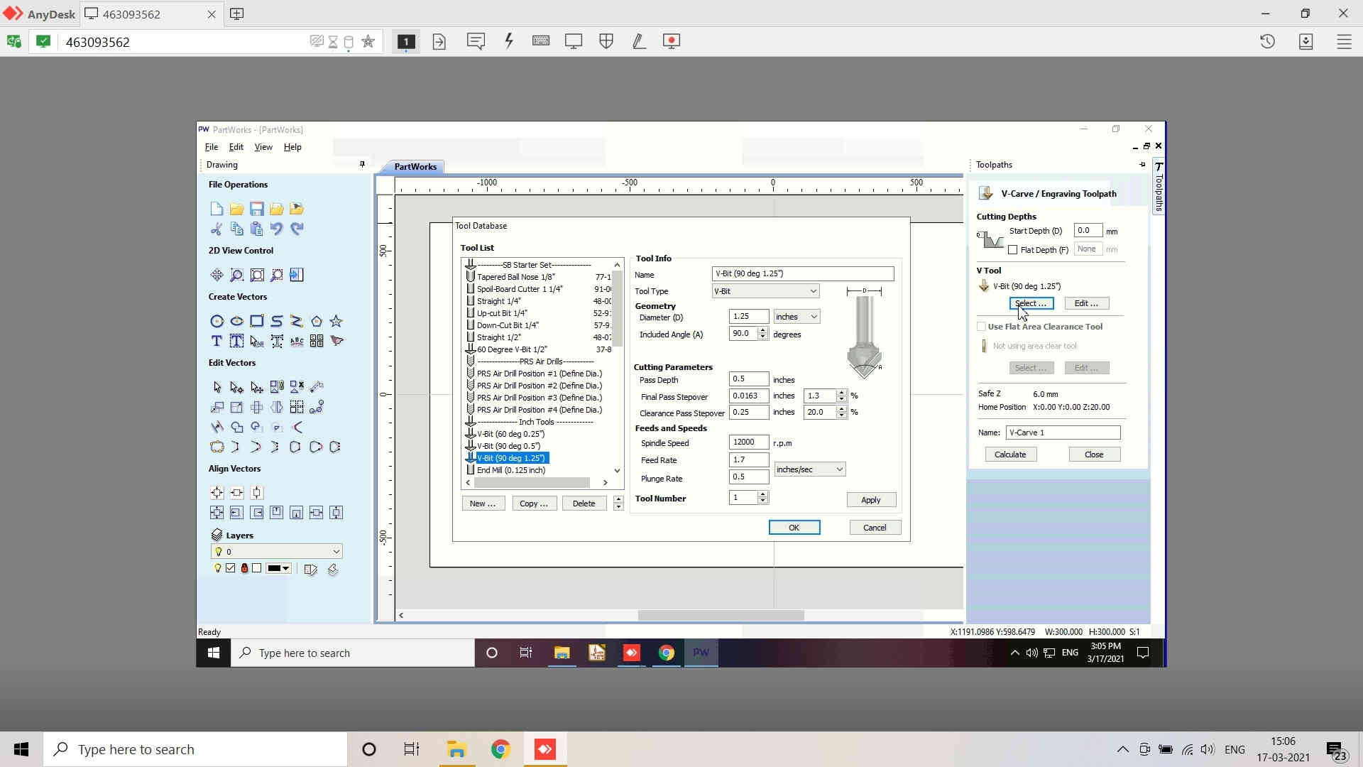
- Be Cautious about selecting the Tool for milling process. I have selected the Staright mill of 6 mm diameter for the job. V bit could be selected for engraving and Ball bit could be selected for having circilar cuts.
- As I have kept the Max depth (Cut Depth) more than the material size, it will warn me about it.
- Select proper Cutting parameters like the fpass depth, stepover and the Feeds and Speeds like the Spindle speed, feed rate and plunge rate for the milling.
- Once all the parameters are set, select the machine vector among the inner, outer and on the line and cut directions Climb (CW) cutting direction or Conventional (CCW) cutting direction
- Save the Toolpath generated for the inner vectors and proceed to generate the toolpath for the outer vectors in th same way.
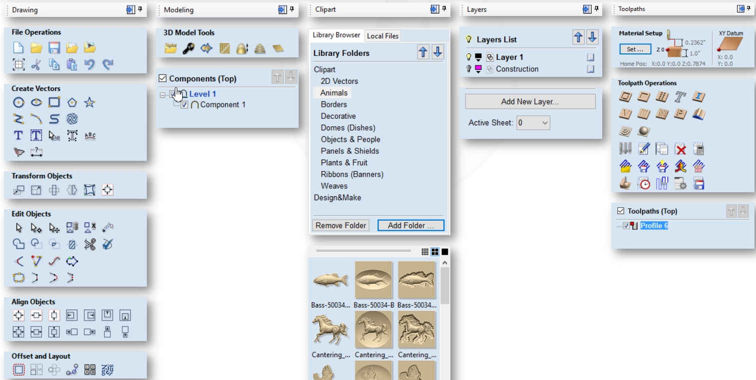
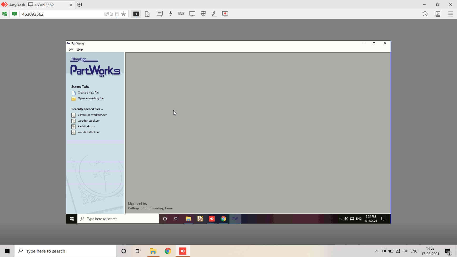 Opening Window of the Partworks Software
 |
 |
|---|

 |
 |
|---|
Partworks / Vectric (Improved Version) Tools details could be found here.
 |
 |
 |
|---|
 |
 |
|---|
Profile toolpaths can be outside, inside or on the selected vectors, automatically compensating for the tool diameter and angle for the chosen cut depth.
Clicking this icon opens the 2D Profile Toolpath form which is shown at the right; the functions in this form are described on the following pages.
Remaining Work:
- Milling of the Design using ShopBot
- Assembling the parts of the design
After the LockDown was liberalized and Unlock was initiated, we approached COE, Pune for accessing the ShopBot CNC Milling Machine for finishing the assignment. We had already created the ToolPaths by remote access of the software (PartWorks).
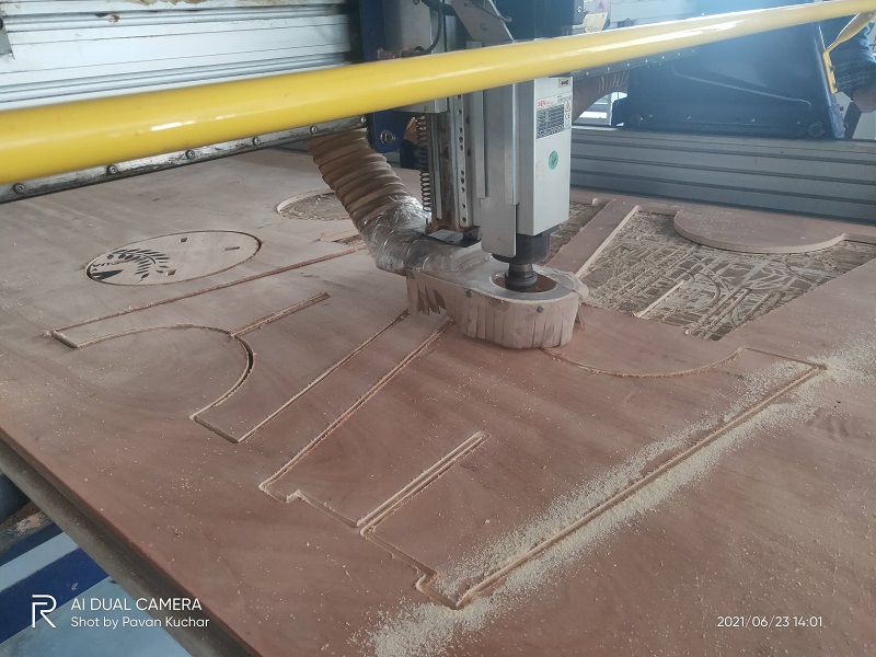
Milling of the Design using Shopbot:
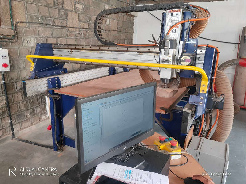
Loaded the 15 mm Plywood Sheet on the ShopBot CNC Milling Machine. The Bed Levelling and Alignment was already done by the Lab Incharge - Apeksha Madam
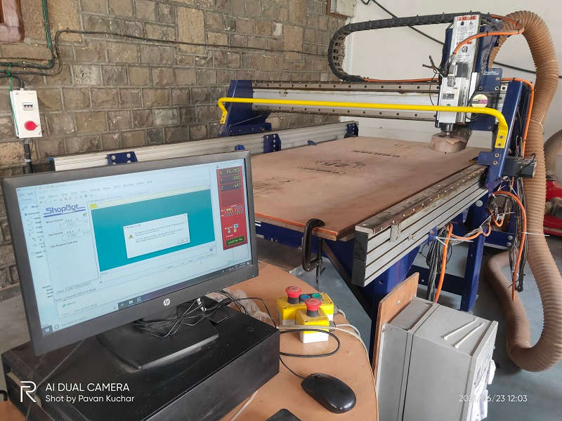
Loaded the Toolpath on the COmputer in Partworks software
The inner holes would be milled first for Pressfir assembly.
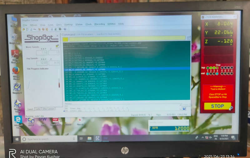
ToolPath on the screen of the Computer while the milling of inner design is ongoing
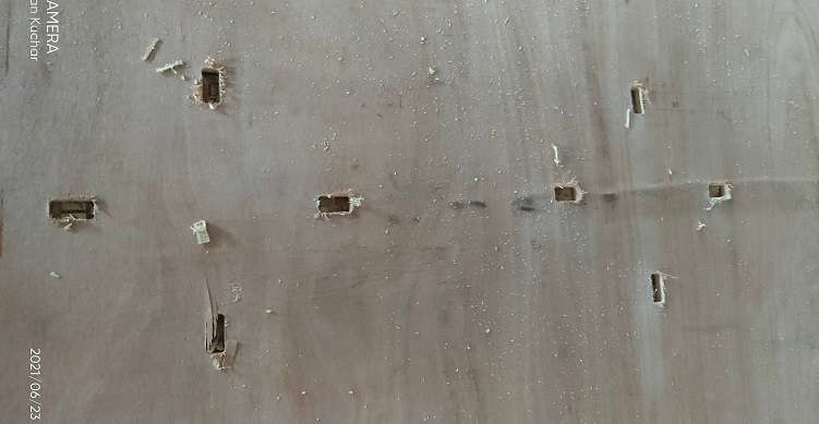
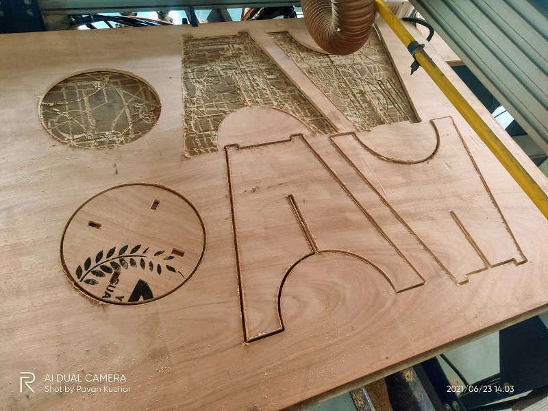
The inner Holes were cut/milled.
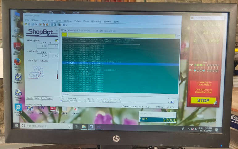
ToolPath on the screen of the Computer while the milling of outer design is ongoing
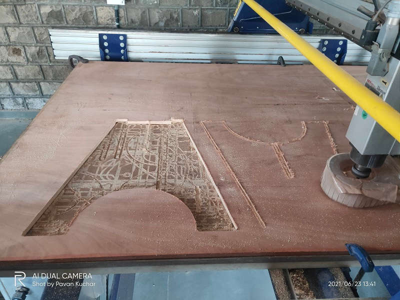
Milling of outer design is ongoing
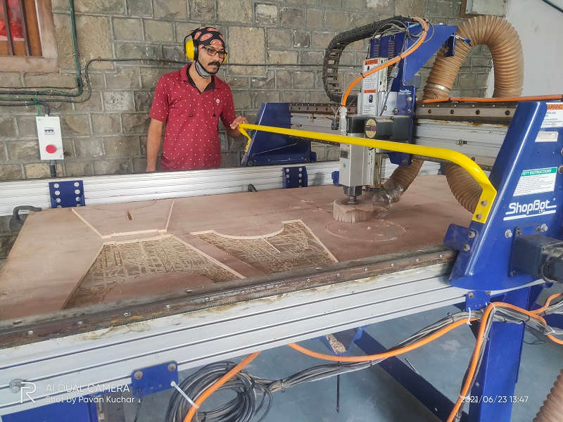
Monitoring the milling in progress
Assembling the Parts of Design (Stool) using Shopbot:
After the milling of the parts of the design, I removed the parts from the sheet and started assembling them. I have used the wooden hammer for pressfit.
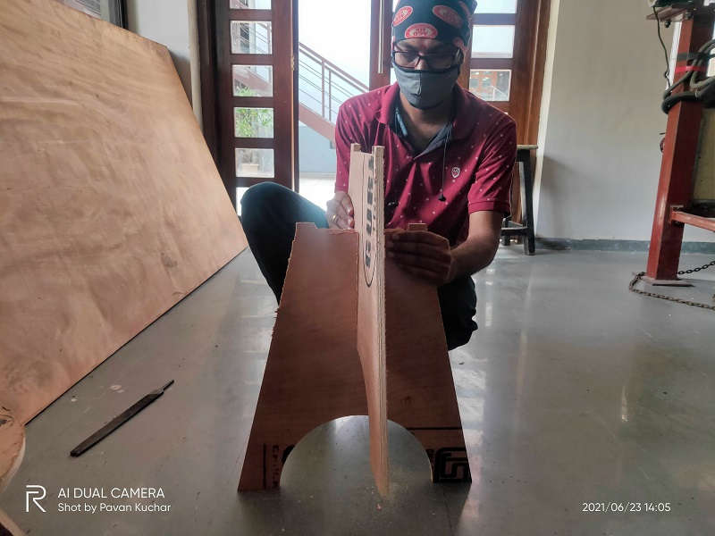
Assembling the Base of the Stool
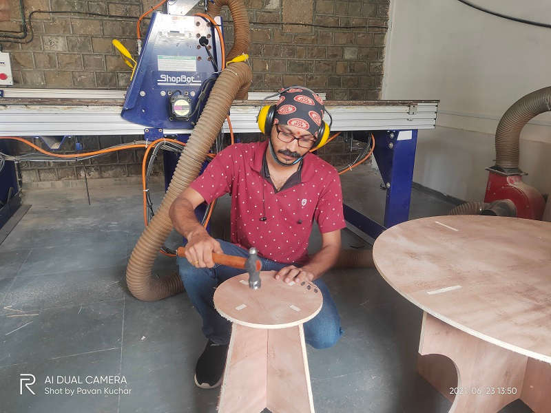
Hammering the Top for pressfit.
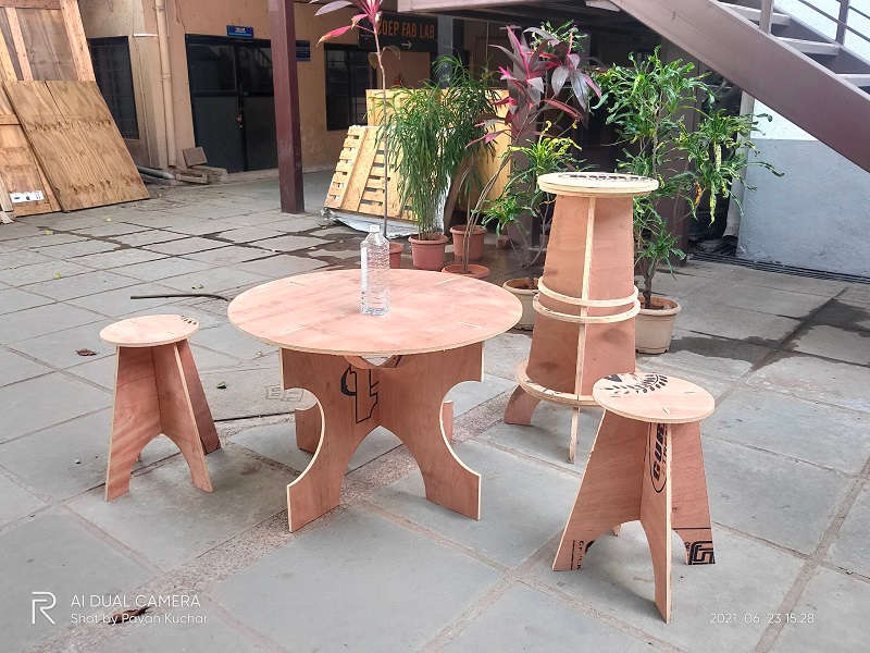
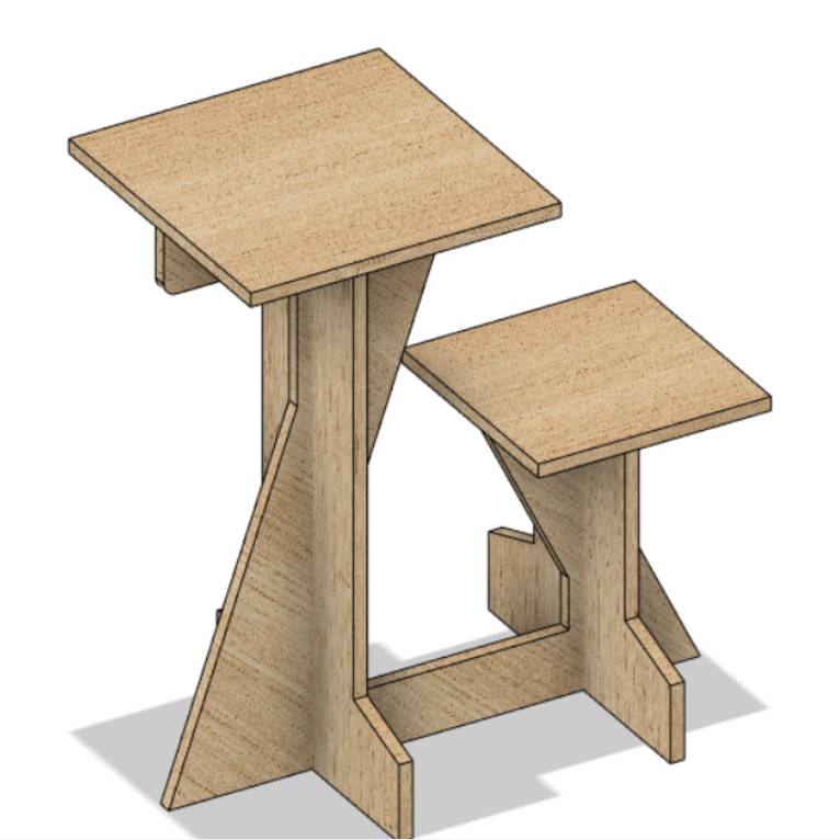
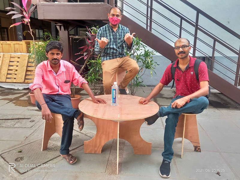
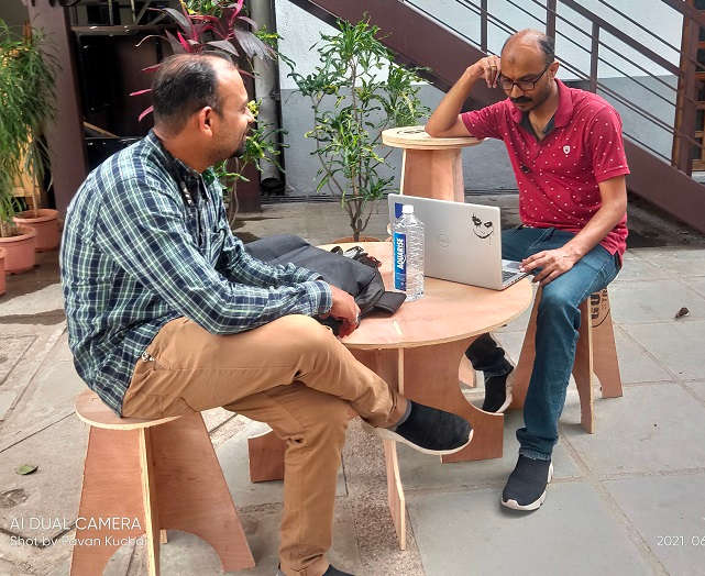
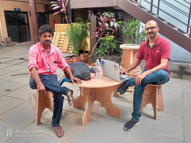
Hero Shot of the Furniture designed by Me, Anand (Bar Stool) and Vijay(Table)
Summary of Steps:-
To summarize the steps explained above, assuming that the right milling bit is in already, and you know it’s sticking out farther than the thickness of the wood;
- Load the actual toolpaths file into the ShopBot software
- Check yet again that nothing is leaning against the ShopBot
- Turn on the vacuum, turn on the spindle and press START
- After the full job is done:
- Turn off the vacuum
- Turn off the spindle
- Vacuum the bed
- Unscrew all screws (leaving none behind)
- Remove the wood (and probably vacuum the bed again)
- Remove each piece from its tabs with a chisel or box cutter
- Sand, sand, sand away (Reference: Nadieh Bremmer)
Summary:
We had to understand the Parameters, Design a Parametric BIG object, Mill it and Assemble the design for Computer Controlled Machining of the ShopBot PRS alpha at the Govt. College of Engineering, Pune.
- We conducted some test runs on the ShopBot CNC Milling machine for understanding the characteristics of the machine in the group assignment.
- Designed, Milled and assembled the Stul as a part of the assignment.
- Understood about the Do's and DONT's of operating the SHopBot Milling machine.
Video Stream of the Ongoing Milling: