

Embedded Programming:
In this Eighth week of Fab Academy, we had the following Objectives.
Objective:
1. Group assignment:
Details here.This week is having the following Objectives for the Group-
- Compare the performance and development workflows for different microcontroller families
- Document your work (in a group or individually)
2. Individual assignment:
- Read the datasheet for the microcontroller you are programming
- Program the board you have made to do something, with as many different programming languages and programming environments as possible.
Learning Outcomes:
- Identify relevant information in a microcontroller datasheet.
- Implement programming protocols.
Checklist:
Linked to the group assignment page ✔
Documented what you learned from reading a microcontroller datasheet. ✔
Programmed your board ✔
Described the programming process/es you used ✔
Included your source code ✔
Included a short ‘hero video’ of your board ✔
Opening Quotes:
- "There are only 10 types of people in this world. Those who know binary and those who dont."
- while (no Success);
{
try Again ();
if(Dead)
break;
}
1. Group assignment:
Various tasks were divided amonst us and Mohit Ahuja would take up the responsibility of the Group Assignment for this week. We had to Compare the performance and development workflows for different microcontroller families and document it.
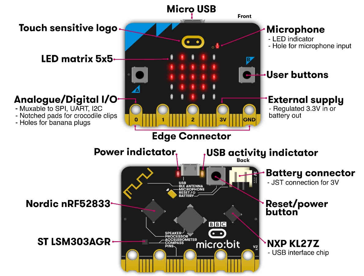
We had explored Microbit, Raspberry pi and Arduino IDE.
Microbit is a simple way of coding complex algorithms. We had accessed the https://makecode.microbit.org/ for coding the microbit. We were able to see the simulations of our programs. The code was in the form of blocks. I have personally coded for motion, flashing heart, capacitive touch and table of 9. The hex files for this Codes could be found in the downloads.
Raspberrypi is a small computer. We accessed the https://projects.raspberrypi.org/en/projects/physical-computing/2 for the LED blinking with switch code.
Details of the Group Assignment could be found here.
2. Individual Assignment:
For Individual Assignment, I had to read the Datasheets of Microcontrollers to be used by me. I had to program / code them using various languages and upload the code on the board that I have already made. In the end, I would be explaining the code in terms of how it works and what does the various string mean in the code.
The flow of the Assignment would be like:
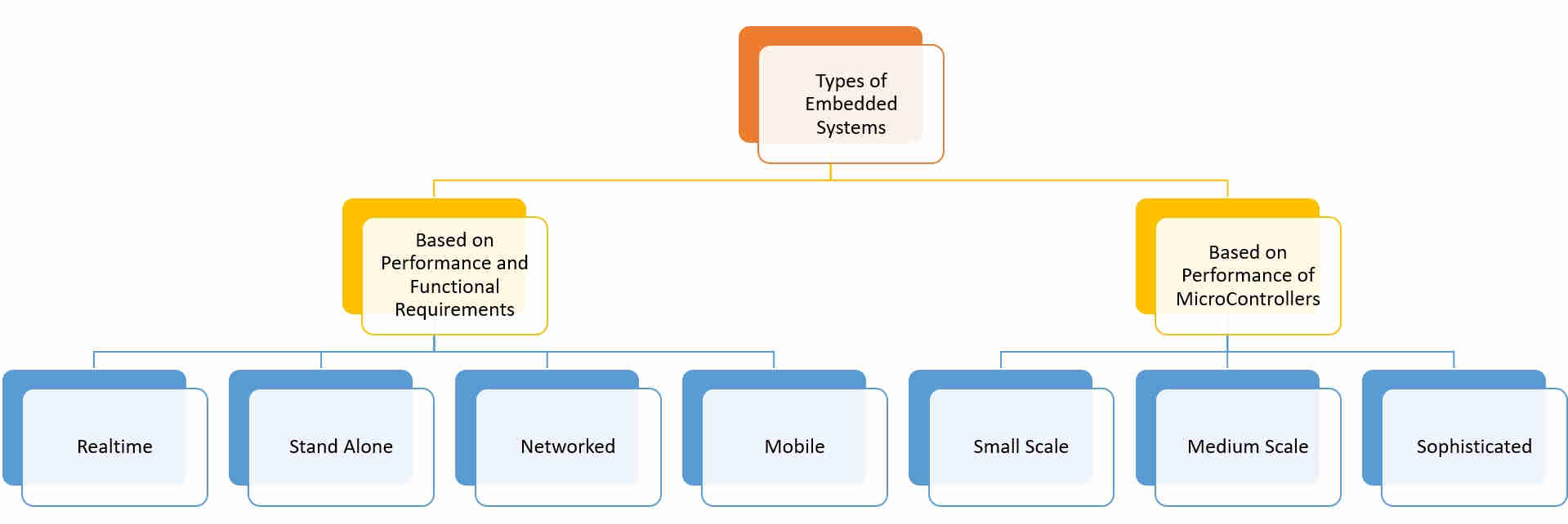
- Embedded System: Embedded Programming and its Basic Structure
- Architectures: Van Newmann v/s Harvard
- MicroControllers v/s MicroProcessors
- Families of MicroControllers: Special focus on AVR and ESP-32
- DataSheets: ATtiny45, Pin Configuration and Description, Features and Specifications, Block Diagram
- Different Programming Languages:Arduino, Embedded C, python
- Uploading and Explaining the Code on the MicroController Board
Being from Non Technical background, I was not at all familiar with the Electronic Components and Terminologies. Thanks to my friends, they told me about the basics of electrical and electronics. I realized that its a very vast field and needs constantly working on it.
I had to decide about the Bill of Material for my Final Project and I had to finalize about the various components that I was supposed to use for it.
The selection of the MicroController depends on various factors, one of them important being the use and application. Also, what is the task that I am supposed to carry out. This week gave me an opportunity to explore and answer about Why am I using ESP-32 for my project. I went through the DataSheet and realized that if I had to connect the module (Interfacing and Connectivity) through Wi-Fi or Bluetooth then ESP-32 is the answer.
Embedded System and Programming - An Introduction:
An Embedded System can be best described as a system which has both the hardware and software and is designed to do a specific task. The Processor is the heart of the Embedded System and it can be anything like a Microprocessor, Microcontroller, DSP, CPLD (Complex Programmable Logic Device) and FPGA (Field Programmable Gated Array). All these devices have one thing in common: they are programmable i.e. we can write a program (which is the software part of the Embedded System) to define how the device actually works.
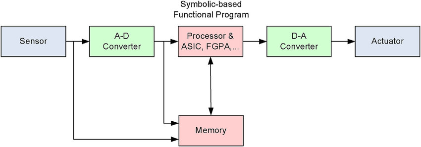
Embedded Software or Program allow Hardware to monitor external events (Inputs) and control external devices (Outputs) accordingly. During this process, the program for an Embedded System may have to directly manipulate the internal architecture of the Embedded Hardware (usually the processor) such as Timers, Serial Communications Interface, Interrupt Handling, and I/O Ports etc. There are many programming languages that are used for Embedded Systems. In the process of making a better embedded system, the programming of the system plays a vital role and hence, the selection of the Programming Language is very important. In this assignment, we trying to develop the code using different languages and environments.
Difference between MicroProcessor and MicroController:Details
Both ICs have different applications and have their own advantages and disadvantages. They can be differentiated in terms of Applications, structure, internal parameters, power consumption, and cost.
| MicroProcessors | MicroControllers |
|---|---|
| Microprocessor only have CPU in the chip like most of the Intel Processors | Microcontroller also have RAM, ROM and other peripherals along with the CPU or processor. |
| Task is not predefined; is used where intensive processing is required; used for media streaming, simulation, editing image, web browsing, gaming, creating a document etc. | designed for a specific task; used to do the same assigned task repeatedly in many electronic appliances like washing machine, microwave oven, timer, etc |
| Parameter | MicroProcessor | MicroController |
|---|---|---|
| Clock speed: | Higher in the range of 1 GHz to 4 GHz | Lower in the range of the 1 MHz to 300 MHz. |
| Memory: | RAM:512 MB to 32 GB; ROM:128 GB to 2 TB. | RAM:2 KB to 256 KB; ROM:32 KB to 2 MB. |
| Peripheral interface: | USB, UART, and high-speed Ethernet. | I2C, SPI, and UART. |
| Programming: | can be changed for different applications. | NO option for the modification of the program. |
| Bit Size: | 64-bit binary data handled at the same time | 8 bit, 16 bit or 32 bit. |
| Power Consumption: | Higher | Lower |
| Cost: | Higher | Lower |
Microcontrollers:
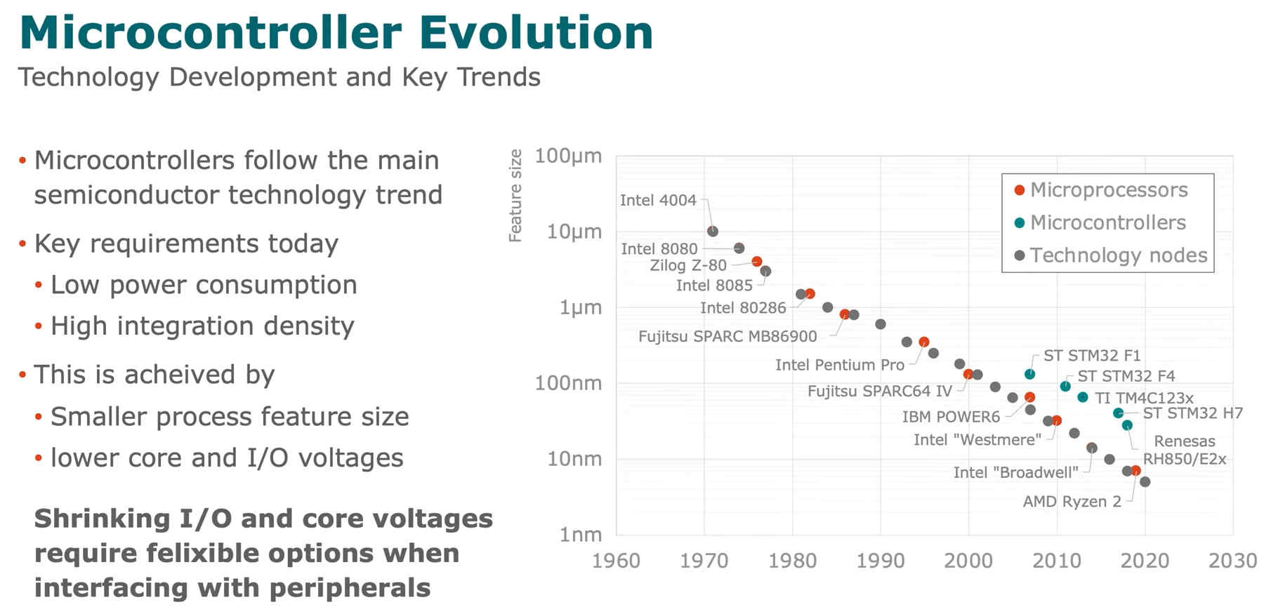
The microcontroller is an embedded computer chip that controls most of the electronic gadgets and appliances people use on a daily basis, right from washing machines to anti-lock brakes in cars.
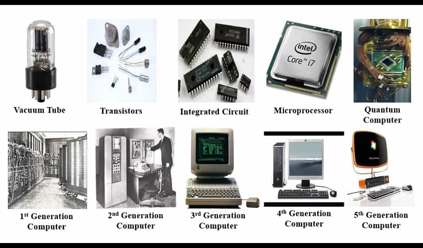
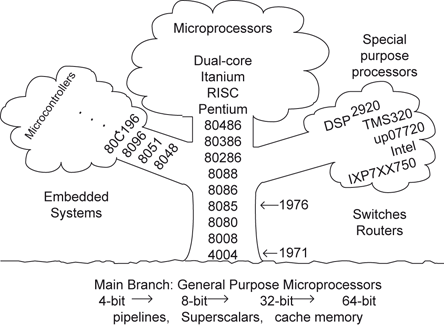
During 1970 and 1971, Intel was working on inventing the world’s first microprocessor and Gary Boone of Texas Instruments was working on quite a similar concept and invented the microcontroller. Boone designed a single integrated circuit chip that could hold nearly all the essential circuits to form a calculator; only the display and the keypad were not incorporated. It was given a mundane name of TMS1802NC. It had five thousand transistors providing 3000 bits of program memory and 128 bits of access memory!! So, it was possible to program it to perform a range of functions. The present day microcontrollers like AVR, and PIC have become smaller and sleeker yet more and more powerful.
Microprocessor is an essential component of computer. As well as it is one of the chip that is combined with memory and special purpose chips and preprogrammed by a software. The main function is to send and receive data to make the function of the computer well. It has the essential part of many gadgets. Also, there are five types such as CISC, RISC, ASIC, superscalar processor, etc.
Structures of MicroControllers:
The basic structures of MicroControllers could be classified on the basis of Data Path considerations, Control Unit considerations and the Two basic memory Structures.
Data Path Considerations:
- N-bit processor
- – Width of data path busses, registers, memory data interface
- – 8-bit, 16-bit, 32-bit common for embedded application; 32/64 for workstations/servers
- • Width of program counter determines directly accessible code space
Control Unit Considerations:
- RISC/CISC
- – RISC style allows for pipelining and load/store type operations but fewer addressing modes and operations
- – Distinction blurring
- • Clock frequency
- - Perios must exceed longest register-register transfer latency
- - Typically memory access slow (and thus slower clock or wait states)
Basic Memory Structure: Von Neumann v/s Harvard Architecture-
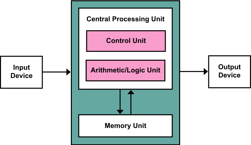
In a Von-Neumann architecture, the same memory and bus are used to store both data and instructions that run the program. Since you cannot access program memory and data memory simultaneously, the Von Neumann architecture is susceptible to bottlenecks and system performance is affected.
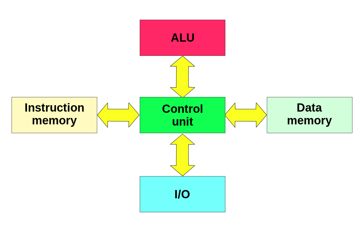
The Harvard architecture stores machine instructions and data in separate memory units that are connected by different busses. In this case, there are at least two memory address spaces to work with, so there is a memory register for machine instructions and another memory register for data. Computers designed with the Harvard architecture are able to run a program and access data independently, and therefore simultaneously. Harvard architecture has a strict separation between data and code. Thus, Harvard architecture is more complicated but separate pipelines remove the bottleneck that Von Neumann creates.
Some reasons for popularity of MicroControllers are as:
- Speeds design time (many peripherals integrated)
- Simplifies I/O interfacing
- Reduce/eliminate external memory
- Single chip solution can help optimise for power, board space, cost,…
Families of MicroControllers: Details here.
- PIC (www.microchip.com)-Versatile, robust, low-power, low-cost controller. Also, they are – Harvard architecture (8-bit data space) and limited registers, instruction set and addressing modes (RISC like)
- 8051- Popular 8-bit uC made by Intel
- ARM (not a chip maker - IP based)- 32-bit RISC processor core embedded into microprocessors, ASIPs and uC; Many applications: network, digital cameras, PDAs, mobile phones; – Windows CE, Linux, Palm OS, Symbian OS, and Java OS, many RTOS options
- Freescale (Motorola) HCS12 family- Fairly complex CISC processor with a large number of multi-cycle instructions
AVR Family of MicroControllers: Reference link.
AVR is a family of microcontrollers developed since 1996 by Atmel, acquired by Microchip Technology in 2016. These are modified Harvard architecture 8-bit RISC single-chip microcontrollers. AVR was one of the first microcontroller families to use on-chip flash memory for program storage, as opposed to one-time programmable ROM, EPROM, or EEPROM used by other microcontrollers at the time.
AVR microcontrollers find many applications as embedded systems. They are especially common in hobbyist and educational embedded applications, popularized by their inclusion in many of the Arduino line of open hardware development boards.
- Basic families:
- tinyAVR – the ATtiny series
- megaAVR – the ATmega series
- AVR Dx – focussed on HCI and analog signal conditioning
- XMEGA – the ATxmega series
- Application-specific AVR such as LCD controller, USB controller, advanced PWM, CAN, etc
- FPSLIC (AVR with FPGA)
- 32-bit AVRs - 32-bit chips with ARM Cortex-M and Cortex-A cores.
We have been using the Attiny processors from various boards till now. So for starters I decided to study the datasheet for attiny family. I have used ATtiny 45 for Fab ISP and echo Hello World in the Electronics Production Week.
Datasheets!
What is a data sheet? - It is a document that summarizes the performance, technical and software characteristics in enough detail that anyone can integrate the component into a system. It is usually made by the component manufacturer. An electronic datasheet specifies characteristics in a formal structure that allows the information to be processed by a machine. Such machine readable descriptions can facilitate information retrieval, display, design, testing, interfacing, verification, and system discovery.
DataSheet of ATtiny45 is available for Download Here.
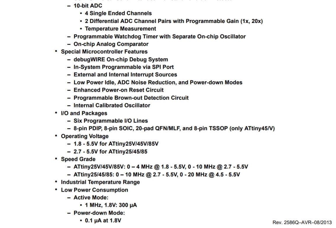
Its a 234 pages datasheet. I have gone through certain important sections like Features, Pin Description, Pin Specifications, Block Diagram, Architecture and Summary.
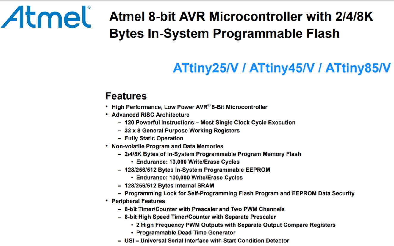
 Datasheet of ATtiny45 MicroController
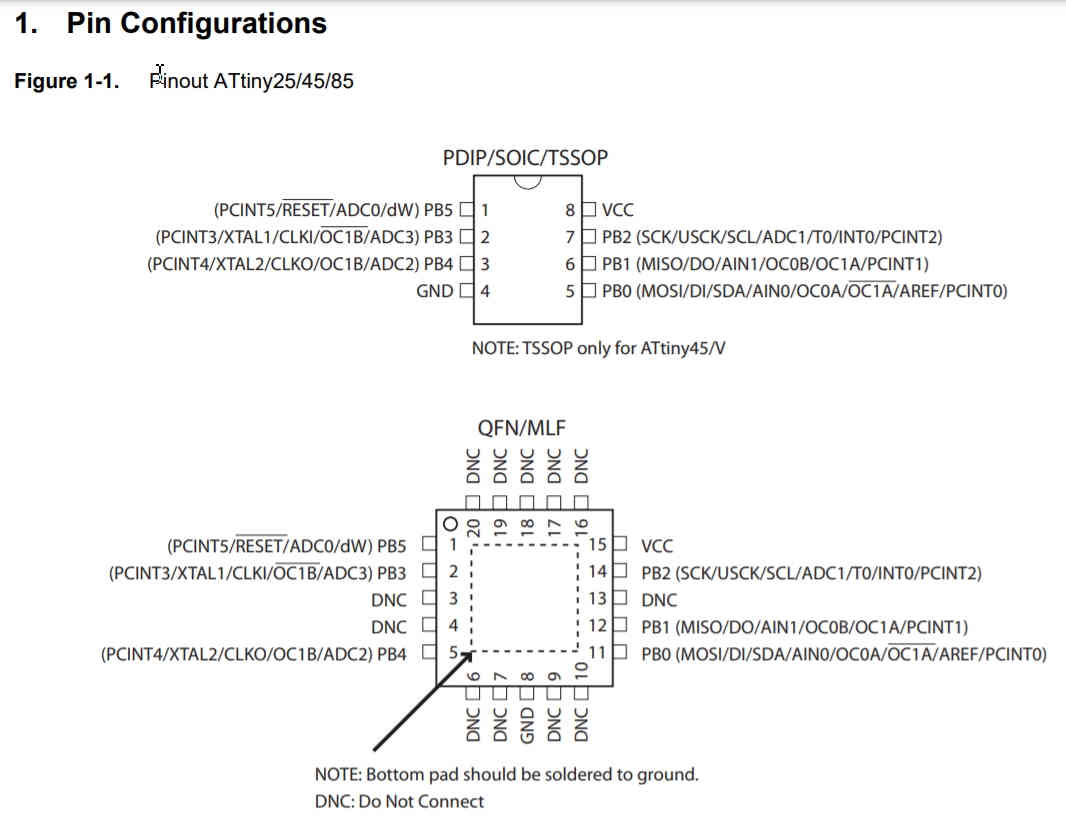
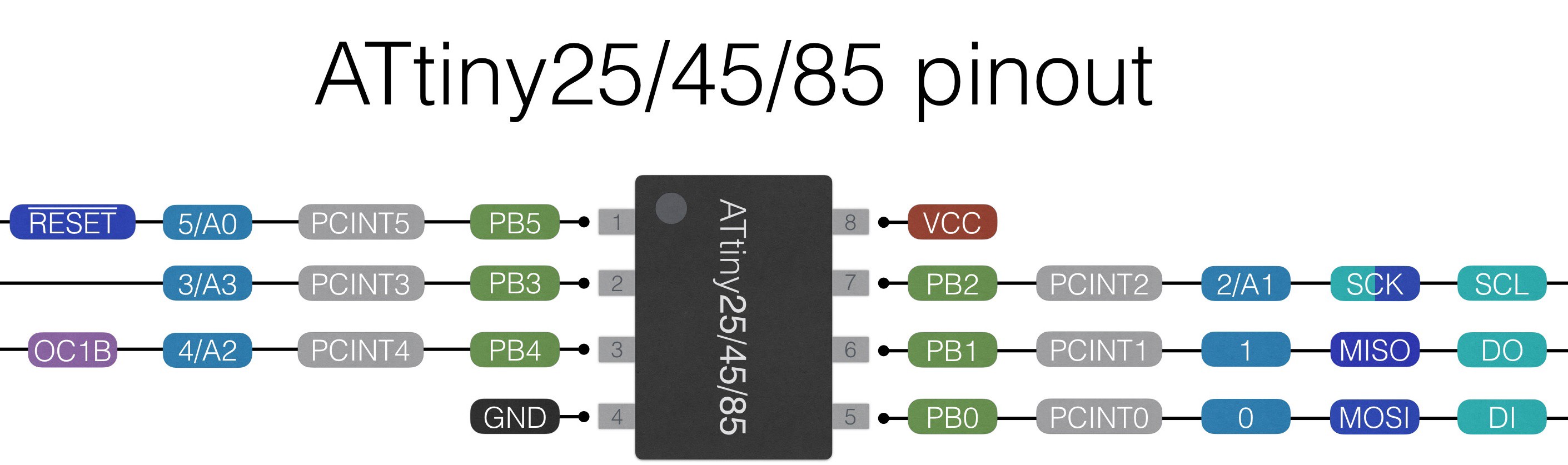
Pin Configuration
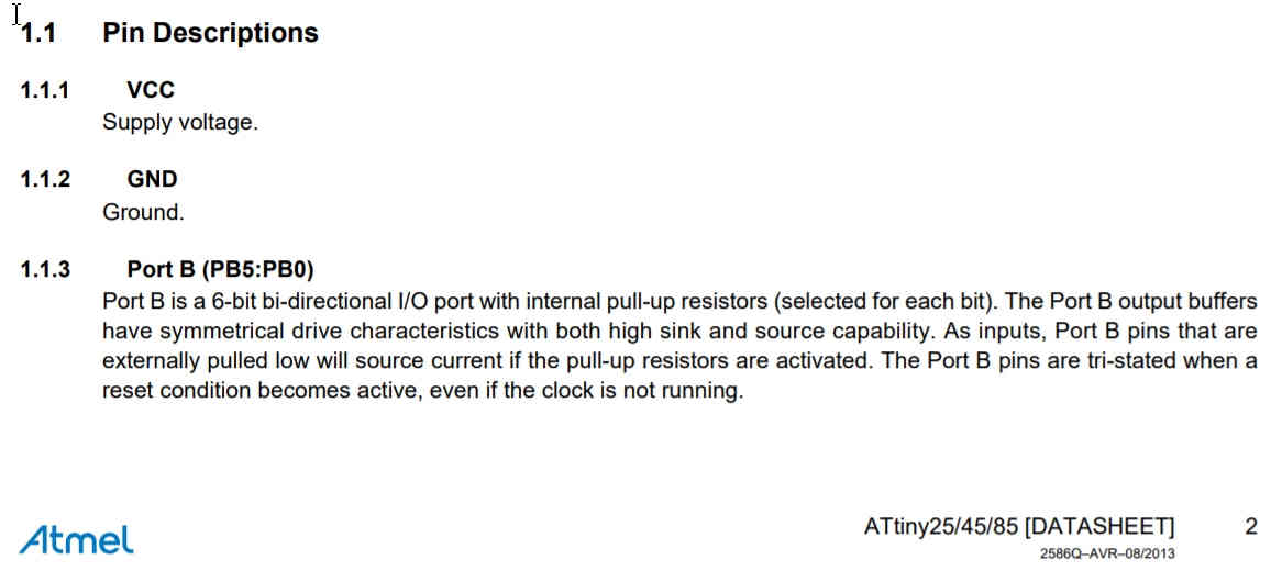
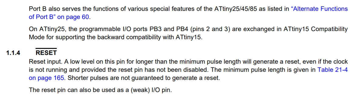
Pin Description
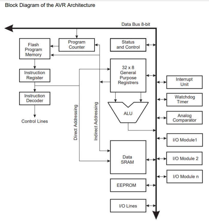
ATtiny 45 Block Diagram Architecture
What I learned after going through the DataSheet of ATtiny 45:
- This MicroController's Architecture is 8 bit (how much data could be sent in terms of binary set of 1 and 0
- It has a 4Kb Programmable Flash Memory i.e why it is called ATtiny45
- Its Clock Speed is 1 MHz but if external Resonator Clock is connected then it may run on 20 Mhz Speed as well
- It has 6 GPIO's i.e general Purpose Input Output pins
- It needs a operational Voltage of 2.8 to 5.5V and
- It has I2C and SPI Communication Protocols.
- This data could be used to decide the number of pins required and for what purpose.
- I cannot use this for my Final Project as I need to attach RFID Scanner, Load Cell Sensor, Proximity Sensor (conditional) and send the data on Cloud. ESP 32 offers these functionalities and features. ATtiny has limitations of GPIO pins, interfacing and connectivity.
Programming Languages:
Computer programming languages allow us to give instructions to a computer in a language the computer understands. The portion of the language that a computer can understand is called a “binary.” Translating programming language into binary is known as “compiling.” Each language, from C Language to Python, has its own distinct features, though many times there are commonalities between programming languages. There are various programming languages and they have evolved with time and applications.
Language Types:
- Machine and assembly languages: Low Level languages
- Algorithmic languages: Fortran, Algol, C
- Business-oriented languages: Cobol, SQL
- Education-oriented languages: Basic, Pascal, Logo, Hypertalk
- Object-oriented languages: C++, C#, Ada, Java, VBasic, Python
- Declarative languages:(ideally) a program specifies what is to be done rather than how to do it
- Scripting languages: Perl
- World Wide Web display languages: HTML, XML
The languages that I have heard of and known to me as per their Use and Purpose are:
- Webpage and App development: HTML, CSS, Java Script, Markdown
- Server Design: MySQL, PHP
- Software to Software Communication: C++ (backend)
- Analytics: R
- Multiple Use: Python (front end)
About Arduino:
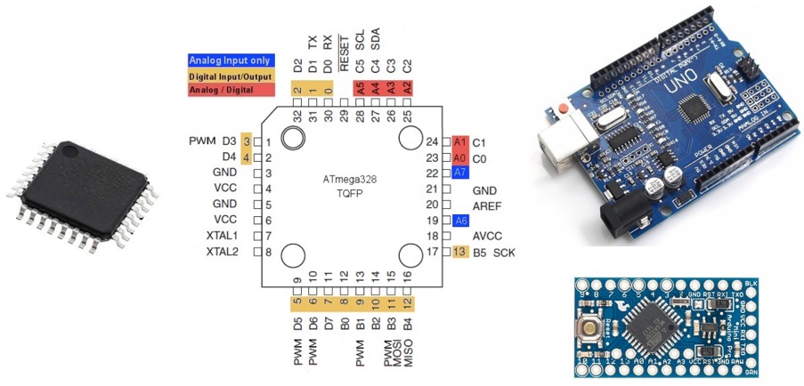 Arduino Uno Board
Arduino is an open-source electronics platform based on easy-to-use hardware and software. Arduino boards are able to read inputs - light on a sensor, a finger on a button, or a Twitter message - and turn it into an output - activating a motor, turning on an LED, publishing something online. You can tell your board what to do by sending a set of instructions to the microcontroller on the board. To do so you use the Arduino programming language (based on Wiring), and the Arduino Software (IDE), based on Processing.
The Arduino hardware and software was designed for artists, designers, hobbyists, hackers, newbies, and anyone interested in creating interactive objects or environments. Arduino can interact with buttons, LEDs, motors, speakers, GPS units, cameras, the internet, and even your smart-phone or your TV! This flexibility combined with the fact that the Arduino software is free, the hardware boards are pretty cheap, and both the software and hardware are easy to learn has led to a large community of users who have contributed code and released instructions for a huge variety of Arduino-based projects.
Various IDE's (Integrated Development Environment)
- Arduino IDE
- Atmel Studio
- Eclipse AVR
- Fireflybr
- Scratch v6 Modkit
About Arduino IDE
- Arduino IDE(Integrated Development Environment) is the software for Arduino.
- It is a text editor like a notepad with different features.
- It is used for writing code, compiling the code to check if any errors are there and uploading the code to the Arduino.
- It is a cross-platform software which is available for every Operating System like Windows, Linux, macOS.
- It supports C/C++ language
- It is open-source software, where the user can use the software as they want it to. They can also make their own modules/functions and add them to the software
- It supports every available Arduino board including Arduino mega, Arduino Leonardo, Arduino Ethernet and more
- Arduino file is called a Sketch as Word file is called a Document, where the user writes code.
- The format of Arduino is saved as .ino
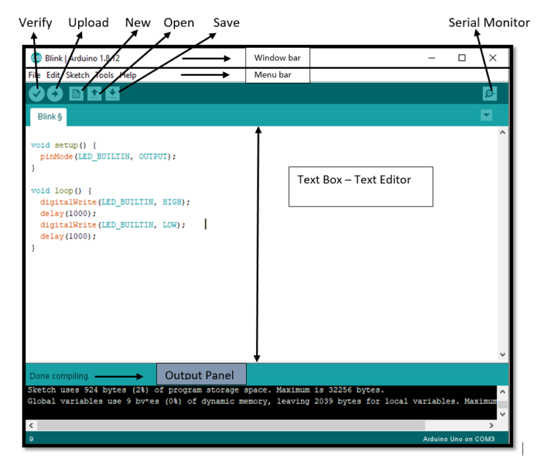
Arduino IDE Window with Default LED Blink Code
How Arduino IDE works?
When a user writes code and compiles, the IDE will generate a Hex file for the code. (Hex file are Hexa Decimal files which are understood by Arduino) and then sent to the board using a USB cable. Every Arduino board is integrated with a microcontroller, the microcontroller will receive the hex file and runs as per the code written.
Programming with Arduino:
Process of Coding in Arduino IDE:
- After installing Arduino IDE, Run the software.
- I have already added the required libraries for ATtiny45 (as they are not supported by Default) in the Electronics Design week.
- To create a new project, select File → New. And then edit the file.
- To open an existing project example, select File → Example → Basics → (select the example from the list). I have selected the Blink
- To avoid any error while uploading your program to the board, you must select the correct Arduino board name, which matches with the board connected to your computer.
- Go to Tools → Board and select your board.
- I have used an Arduino Uno board provided in the Kit to us, but you must select the name, and sometime also the version, matching the board that you are using: Arduino Nano, Arduino Pro Mini 3.3v and 8MHz,...
- Select the serial device of the Arduino board.
- Go to Tools → Serial Port menu. This is likely /COM3 or higher (COM1 and COM2 are usually reserved for hardware serial ports) on Windows computers as I am using a Windows OS Laptop.
- To find out, you can disconnect your Arduino board and re-open the menu, the entry that disappears should be of the Arduino board. Reconnect the board and select that serial port.
- Write the code of LED Blinking
- Simply click the Upload button in the Arduino IDE window. Wait a few seconds, you will see the RX and TX LEDs on the board flashing. If the upload is successful, the message "Done uploading" will appear in the status bar.
- If you have issue uploading your sketch, such as "out-of-sync" message or "programmer not responding" message, check your board type and also avoid connecting the board to your computer with a too long USB cable going through a USB hub.
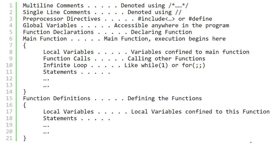
- Basic Structure of Arduino IDE Sketch in Text Editor: An Example-
- 1. void setup()- It has a block of statements written inside parentheses. Here setup() is a function in APL (arduino programming language) used to declare configuration statements for the micro controller ports. While playing with a micro controller, we need to configure different micro controller ports as INPUT source or OUTPUT.
- 2. pinMode (13, OUTPUT);- In this project we are going to blink an LED at port number 13 of micro controller. To blink an LED means, we have to turn it ON and OFF alternatively at a certain interval. So we are going to send commands to turn LED ON and OFF to port 13 of micro controller (arduino board). To do so, we have to configure port 13 as OUTPUT in our program. This is achieved inside the void setup() block.
- 3. void loop () - The next block begins with void loop() – here loop() is another predefined function in arduino programming language (APL).loop() is a function that indefinitely executes statements written inside its parentheses. This function enables the micro controller (or arduino board) to do a set of actions as long as it is ON. In our case, those actions are turn LED ON and OFF at certain time intervals. So here is how we are going to tell arduino board to do the ON and OFF process.
- 4. digitalWrite(13, HIGH); – which is an instruction to write some data to a particular micro controller port in arduino board. We have connected LED to pin 13. To turn it ON, we have to supply a voltage at pin 13. We are going to do that via software commands. Since our arduino board is connected to PC via USB, a +5 volts readily available. We need to pass this voltage to port 13 of arduino board. To do so, APL has a keyword instruction called HIGH. So we just need to write an instruction digitalWrite(LED,HIGH); and this instruction when executed by micro controller will supply a +5 volts at port 13. This voltage will power LED and it will turn ON.
- 5. digitalWrite(13,LOW); - Now we need to turn LED OFF. We just need to disconnect the voltage supply given at port 13. This command will cut off supply at port 13 and LED will get OFF.
- 6. delay (250); - It is a setting a time interval in between ON and OFF time. The time given for delay is in Milli Seconds.
- 7. break: Break is used to exit froma for, while or do....while loop; bypassing the normal loop condition. It is also used to exit from a switch case statement.
- (//): These instructions are written by the Programmer which helpothers to understand the command line of the program.
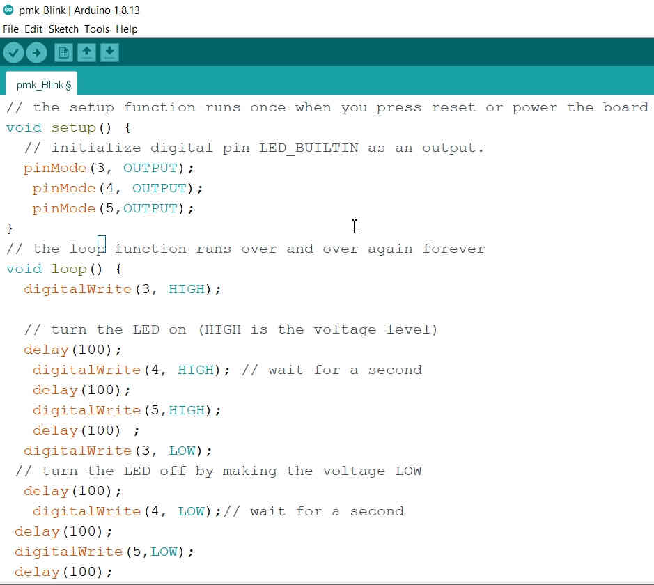
LED Blink Programming in Arduino:
Codes for blinking one LED are available. I decided to use three LED and blink them. So, I took the Default LED Blink program from the Examples section and modified it. I connected the three LED on GPIO pin no. 3, 4 and 5 of the Arduino Uno (ATmega328) board. I also reduced the delay to 100 milliseconds to have faster blinking speed.
Click this Link for watching this video on YouTube.
3 LED Blinking through Arduino Uno(ATMega328P):
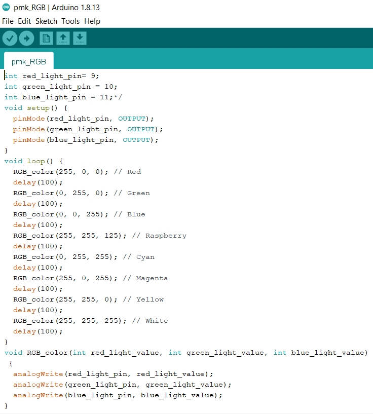
RGB LED Blinking :I decided to use RGB LED and blink them because Rahul(colleague) has already used it in Electronics Design week. I liked RGB and wanted to experiment with it. I used the code from one of the tutorial, compiled and uploaded on the board. In the tutorial, the RBG LED were attached on the Pin 3, 4 and 5. I changed it to Pin no. 9, 10 and 11. I also changed the delay from 500 milliseconds and reduced it to 100 milliseconds.
Few thing that I noticed that it had already configured the pins by using int (integer). Another thing was about defining the RGB color by combining the three colors in different intensities / lumens where 255 being the maximum intensity. And the last thing which was different was that the analogWrite was used. I understood that analog is used when we want to control the luminosity and digital is used when we simply want to turn ON or OFF the LED.
Click this Link for watching this video on YouTube.
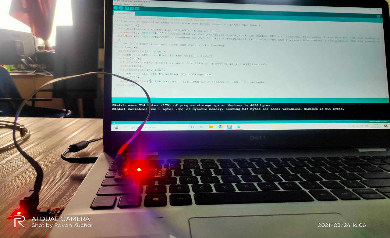
Video Stream of the Uploading and Execution of LED Blink Code:
RBG LED Blinking with Rainbow Colors using Arduino Uno
Here, the two LEDs on the Programmed FAB ISP were blinking and only one LED of the two connected on the ATtiny45 was blinking. I then realized that the Pin numbers were incorrect. I was confused in the Digital Pins, Physical Pin numbers and the Pin numbers in Arduino IDE.
 LED Blink Error
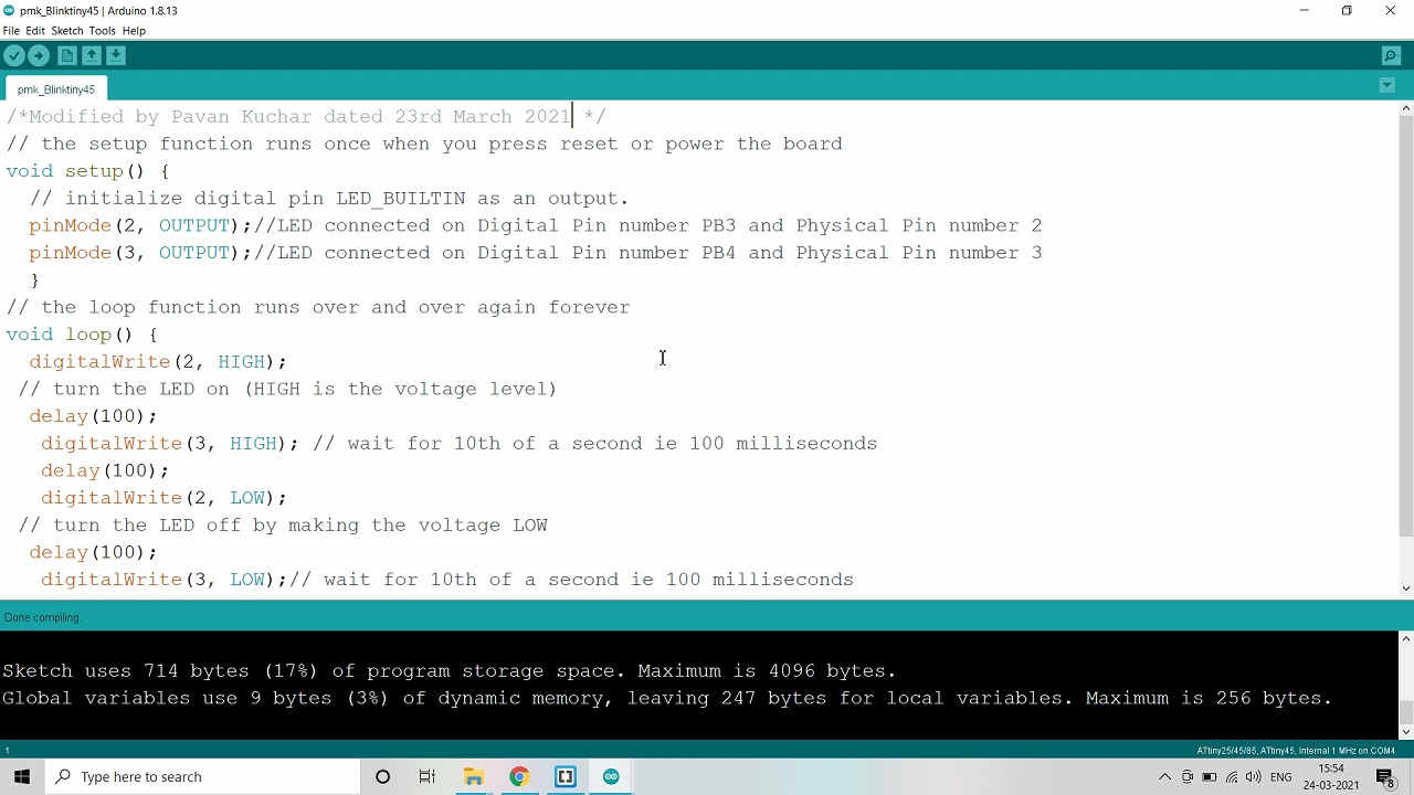
So, I again referred the ATtiny45 Pin out diagram and corrected the Pin numbers from 2 and 3 in the Code to Pin 3 and 4 in the program resulting in the correction of the program and blinking of LEDs.
 LED Blink Error Solved by correcting Pin No. in Code
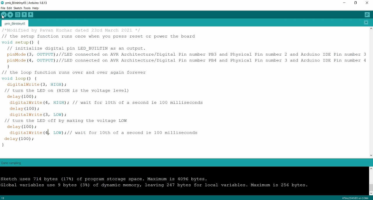
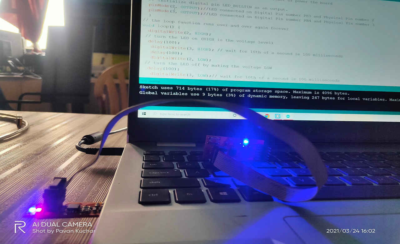
LED Blinking using Programmable ATtiny45 made in Electronics Design Week
Mostly used Menus by me in the Arduino IDE are:
- New : It creates a new File. (Ctrl+N)
- Examples: Examples of a few basic problems for reference.
- Save as… : Allows saving the current sketch with a different name. (Ctrl+Shift+S)
- Preferences : Settings of the IDE software can be changed here. (Ctrl+,)
- Verify/Compile : Checks or verifies your program if any error is there, and displays in the output panel.
- Upload : It compiles and also uploads the code to the Arduino board.
- Upload Using Programmer: Uploads code using Programmer which is available in Tools Tab.
- Include Library : Adds a library to your sketch by inserting #include statements at the start of your code
- Serial Monitor: Serial monitor shows the visual communication by sending and receiving data
- Board: To select the type of Arduino Board
- Port: To select the port where you have connected the Arduino
- Programmer: For selecting a hardware programmer when programming a board or chip and not using the USB type of communication.
- Burn Bootloader: It is used to burn bootloader to the Arduino board
Programming with Embedded C:
Embedded C programming language is an extension to the traditional C programming language, that is used in embedded systems. The embedded C programming language uses the same syntax and semantics as the C programming language.
The only extension in the Embedded C language from normal C Programming Language is the I/O Hardware Addressing, fixed-point arithmetic operations, accessing address spaces, etc.
Basic Structure of Embedded C Program:
LED Blink using Embedded C:
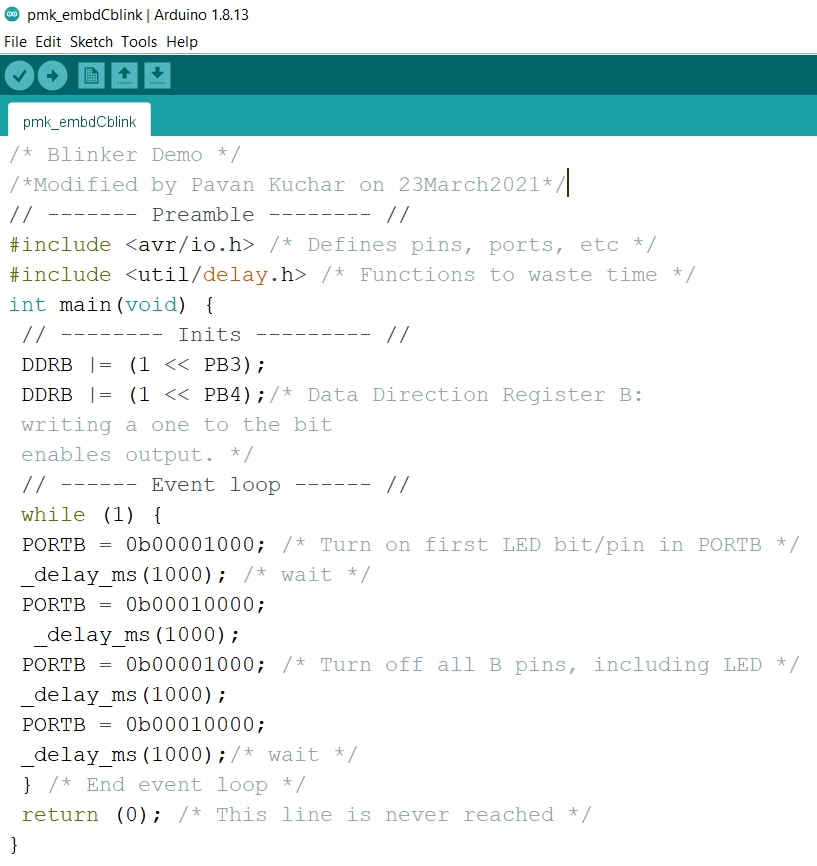
I had used the code from the Book named Make-AVR Programming: Learning to Write Code for Hardware by Elliot Wiliams Page No. 44. Link. I ran this code through Arduino Uno Board and it ran OK.
In my echo Hello World Board, I have connected two LEDs to Pin2 i.e. (PB3) and Pin3 i.e. (PB4) and Switch to MISO. So first step is to define PB3 and PB4 as digital Output. I modified the data direction register (DDR) for this.
The ATtiny 45 has single set of these six (6) GPIO pins.
For port B (PB0-PA5) we use the DDRB command.
To set all pins of PORT B as output we should write : DDRB =0xFF or DDRB =0b11111111. Where:
"1" represents output.
"0x" represents hexadecimal value
"0b" represents binary value
To set any port as high we write PORTB |= (1<<6) or PORTB |= (0b10000000)
To set any port as low we write PORTB |= PORTB &= ~(1<<6) or PORTB &= ~(0b10000000)
After modifying the Default Code from Book, the code for 2 LED blink by me using Embedded C:
I cannot change the pins for my echo Hello World board as they have already been soldered and assigned. I may change the pins for Arduino Uno board as it has three ports as PortB, PortC and PortD and 20 GPIOs
Embedded C Code of LED Blinking through Arduino UnoEmbedded C Code of LED Blinking through FAB ISP
Difference in Size of Codes in Arduino IDE and Embedded C:
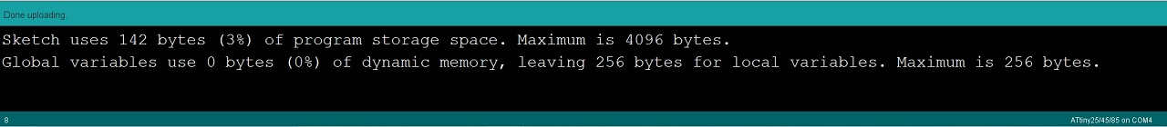
LED Blink Program Size in Embedded C (Size 3%)
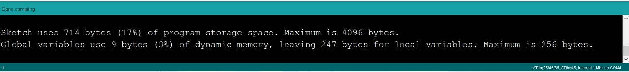
LED Blink Program Size in Arduino IDE (Size 17%)
Summary:
In this week, I have programmed the boards for LED blink with two programming languages in Arduino IDE. The process of writing code in Arduino IDE is easy and it calls directories from various libraries. So, the size of the Code is larger and it takes comparatively more time to compile and upload. On the contrary, the Code in Embedded C is a bit difficult to write as we have to include the various libraries required for our code. But the size of this code is comparatively less and it compiles and uploads very fast. This is because of the Reduced set of Instructions used in the Embedded C Language.
The LED blinking while burning the code in Arduino IDE could be seen for a longer time than the LED blinking while burning the Code through Embedded C language. I may say that Embedded C is lower language than C used in Arduino IDE which makes the machine to process the code faster.
I have learned to:
- Understood the basics of Embedded Systems and Programming.
- Read the datasheets of MicroControllers and extract required information of relevance by going through Features, Pin Description and Configuration, Summary.
- Datasheets are important for choosing the components and operating optimally.
- How to blink LED by connecting the boards through Arduino IDE
- How to write simple codes in Arduino and Embedded C.