

Mechanical Design / Machine Design:
In this Ninth week of Fab Academy, we had room to test our creativity and fabrication skills in making a Machine.
Video of the (ChitraCAR) Chitra-CAR could be found here.Objective:
1. Group assignment:(Mechanical Design)
Details here.This week is having the following Objectives for the Group-
| 1. Group assignment:(Mechanical Design) | 1. Group assignment:(Machine Design) |
|---|---|
| 2. Individual assignment:(Mechanical Design) | 2. Individual assignment:(Machine Design) |
|---|---|
| Document your individual contribution. | Document your individual contribution. |
Learning Outcomes:
- Work and communicate effectively in a team and independently
- Design, plan and build a system
- Analyse and solve technical problems
- Recognise opportunities for improvements in the design
Checklist:
Documented the machine building process to the group page ✔
Documented your individual contribution to this project on your own website ✔
Linked to the group page from your individual page as well as from group page to your individual pages ✔
Shown how your team planned and executed the project (Group page) ✔
Described problems and how the team solved them (Group page) ✔
Listed future development opportunities for this project (Group page) ✔
Included your design files (Group page) ✔
Optionally included an aprox. 1 min video (1920x1080 HTML5 MP4) + slide (1920x1080 PNG) (Group page) ✔
Opening Quotes:
- "Design is not just how it looks like and feels like. Design is how it WORKS" - Steve Jobs
- "The fewer moving parts, the better." - Christian Cantrell
- When you want to know how things really work, study them when they’re coming apart. - William Gibson
- Normal people believe that if it ain't broke, don't fix it. Engineers believe that if it ain't broke, it doesn't have enough features yet. - Scott Adams
- The trick to having good ideas is not to sit around in glorious isolation and try to think big thoughts. The trick is to get more parts on the table. - Steven Johnson
- There's nothing I believe in more strongly than getting young people interested in science and engineering, for a better tomorrow, for all humankind. - Bill Nye
- I have not failed, but found 1000 ways to not make a light bulb. - Thomas Edison
- Knowing there is a structure, hidden or felt, to the random gives pleasure. - Cecil Balmond
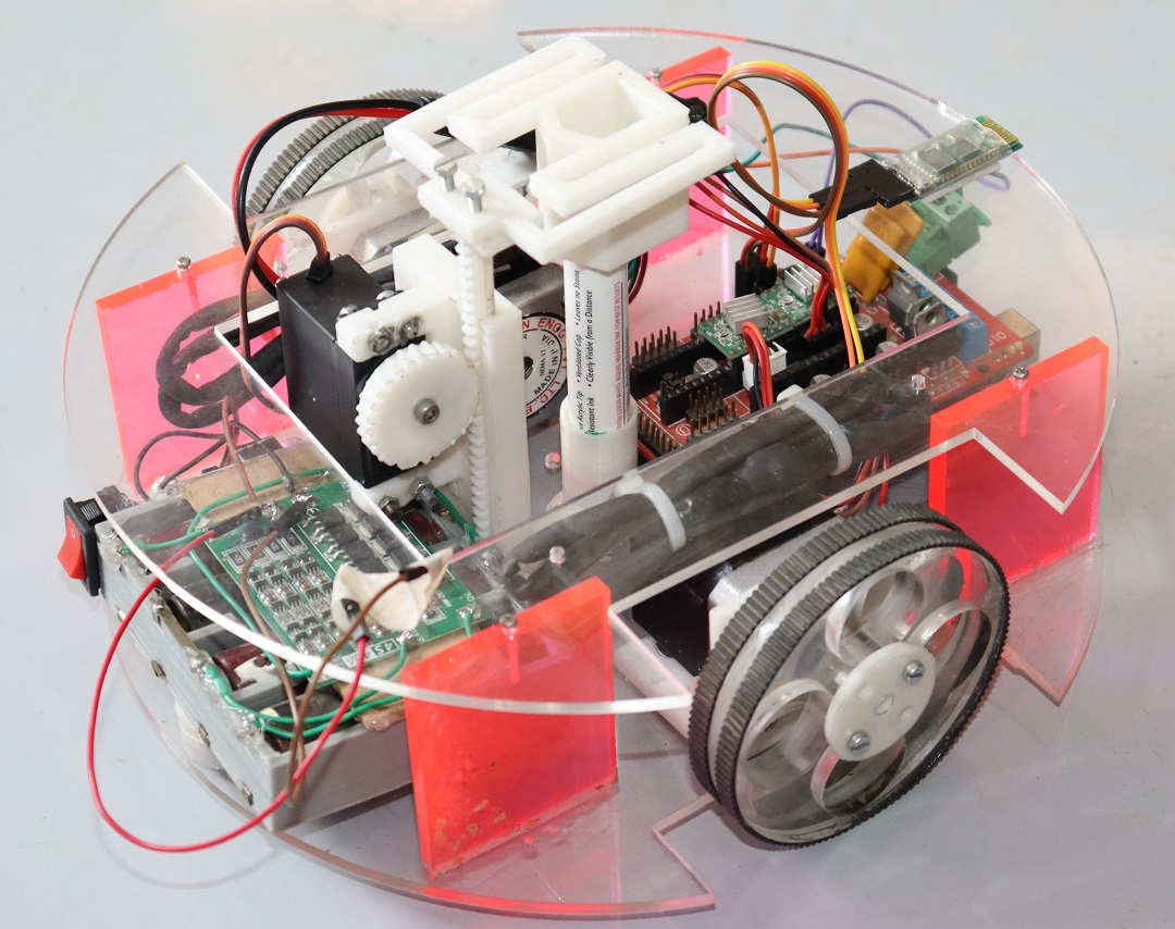
Chitra-CAR
1. Group assignment: Details here.
The flow of Group Assignment is as follows:
- Rationale behing the Name
- Objective / Need and Application
- Process:
- Sketch / Design
- Designing
- 3D Printing and Laser Cutting
- Assembling the Components and Parts
- Firmware Building
- Test Run / Manual Testing
- End Result:
- through Blender
- through G-Code
- through Firmware
2. Individual assignment:
This week was having a lot more to learn. Everyone was engaged in working on their mechanisms and we had to collaborate and share our work each other for the Machine to work.
I took the responsibility of Documenting the Group Assignment and also designing the Mechanism of Z Axis of the Router.
Brainstorming about the Idea for Machine Week:
We had brainstormed about the concept and what to make for this machine and mechanical design week.
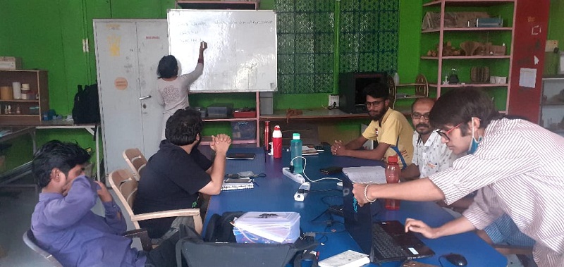 Listing down the Ideas |  Discussion over Ideas in Room |
|---|
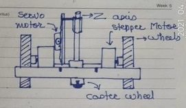
Initial Sketch of the Chitra-CAR
Inspiration for the ChitraCar (DrawMobil / Chitra-CAR)
Chitra-CAR means an Automobile / Car which can Draw. Chitra is a Hindi Word for an Image. We had also thought of KalaCAR which means a Car which has Art/Skills.
Ideas like making a CarromBot which can play Carrom or atleast pick, place and Shoot a Striker, a De-Weeder etc. were thought.
We have explored the CNC machines in our Lab. and found that they are big in size and limited by the movement along X and Y axis. We also were inspired by the projects and machines of previous year like the Plotter that operates by hands and a plotter which prints on the walls. This tempted us to think of making something which could be mobile, smaller in size and free from constrains.
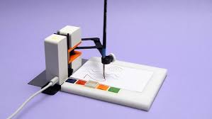
Thus, the Idea of making a small robot which would draw on the plain surface popped up and we agreed on the same. Two of the memvers were not proficient enough in Designing, Coding and technicalities of the components as well. So, the group had to think of something where everyone would be able to contribute. The Artie 3000 which is an educational robot was also referred.
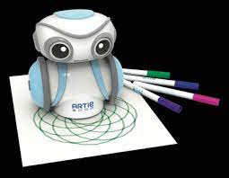 Artie3000 Drawing Robot |  Anatomy of Artie3K |
|---|
 Tiny DIY Drawing Bot1 | 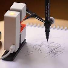 Tiny DIY Drawing Bot2 | 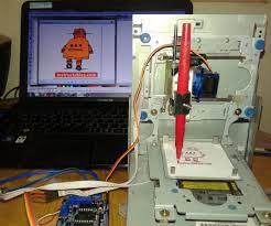 Tiny DIY Drawing Bot3 |
|---|---|---|
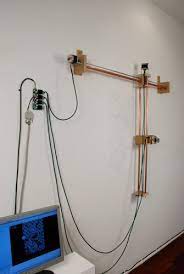 DIY Drawing Bot on Walls suspended on Cables1 | 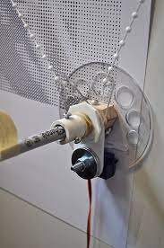 Movement Mechanism | 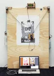 Drawing Bot on Walls suspended on Cables2 |
 | 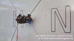 |
|---|
Need of the ChitraCar (DrawMobil / Chitra-CAR):
The CNC Routers / machines in our Lab are constrained by the movement along X and Y axis. So, inspired from the Wall Printer and the Hand Router, we decided to overcome this constraint and build a machine which would print / plot irrespective of the size of the image. So, we designed and made this Chitra-CAR.
Applications of the ChitraCar (DrawMobil / Chitra-CAR):
This machine is not limited by the movement along the axes and thats why it offers plotting / drawing images of any scale. It has multitude of applications by making modifications in the Z axis assembly. If the Pen is replaced by the sprayer or cutters; it may offer various applicability like-
- De-weeding in the fields
- Picking the objects
- Spray Painting the Signs on the Roads
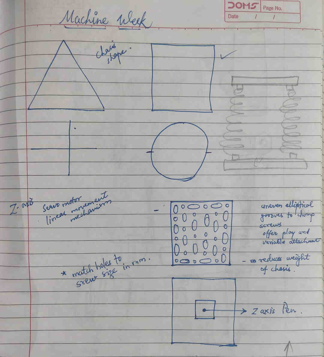
Z Axis Assembly of the Chitra-CAR:
I had to design the Z axis i.e. the Pen Holder of the Machine which will lift up when not drawing and slide down while drawing. Also, the Pen holding mechanism had to have some sort of Flexibility or Shock Absorbing Mechanism to withstand the Shocks and the jerks of the Servo motor in case of sudden descent.
I had to take care that the Tip of the Pen remains in contact with the Bed area with enough pressure and also that it is free from excessive force in downward direction. The Pen should not incline in one direction due to sliding on the surface so it needed to be held at two places.
Few Drawings and Mechanisms that I thought of are:
 Initial Shape of Machine for placing the Z Axis | 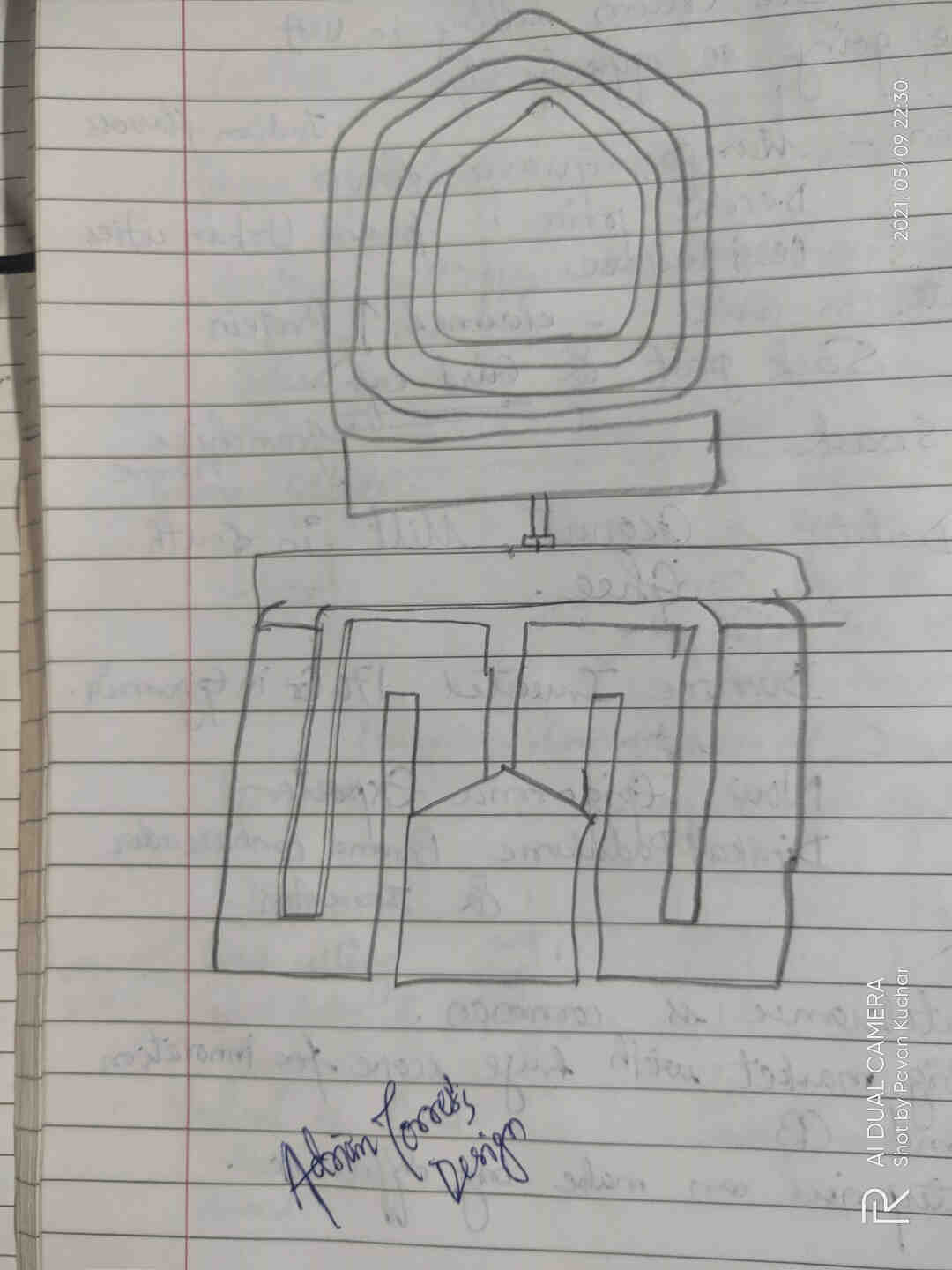 Adrian Torress's Design |
|---|
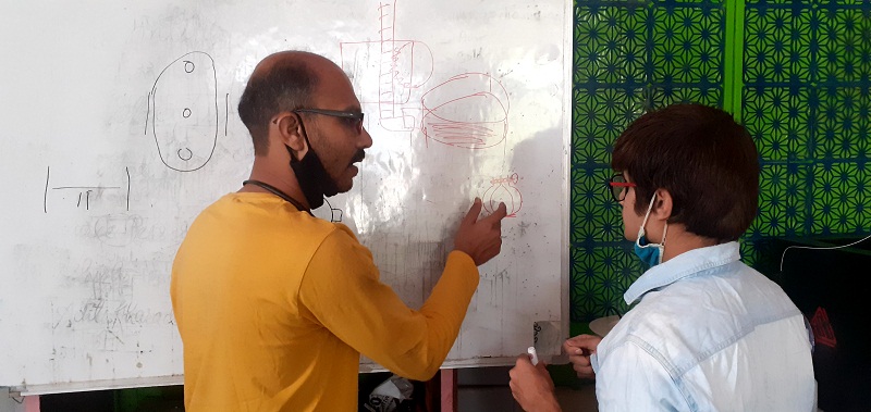
Discussion with others about their Opinion
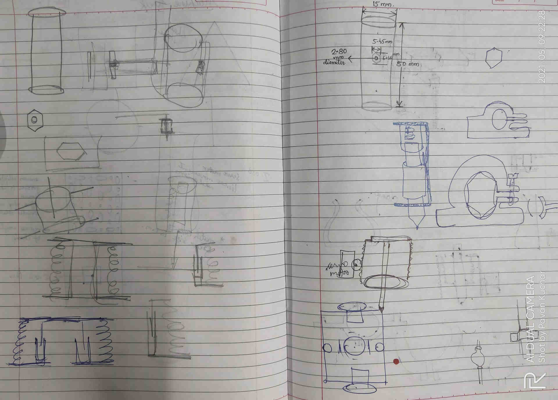
Spring and other Mechanism for Flexibility
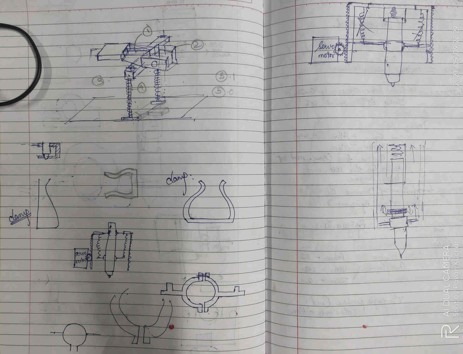
Clamp and other Mechanisms for holding the Pen at two points
I figured out about what would be needed for the Z - Axis Assembly to function. It would need -
- Servo Motor - for the lifting of the Z Axis upward and downward
- Liner Motion Actuator Assembly - as the Servo motor would lift the Pen at a particular angle of 90 or 180 degrees.
- Clamp like Assembly to hold the Pen in place
Servo Motor:
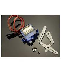
We have used SG-90 Mini Servo Motor in our Machine. I tried to understand the mechanism and Working Principle of the Servo Motor. Servos are controlled by sending an electrical pulse of variable width, or pulse width modulation (PWM), through the control wire. It equips Carbon Fiber Gears which makes the servo motor much lighter than the same metal gear motor. The TowerPro SG90 9g Mini Servo is a 180° rotation servo. It is a Digital Servo Motor that receives and processes PWM signal faster and better. It equips sophisticated internal circuitry that provides good torque, holding power, and faster updates in response to external forces. The Data sheet of the Servo Motor could be found here. The Wire Description of Servo Motor is -
- RED: Positive
- BROWN: Negative
- ORANGE: Signal
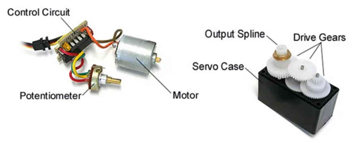
Inside Mechanism of the Servo Motor
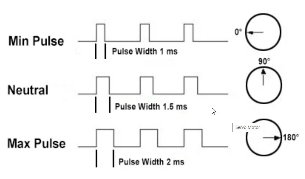
Servo Control by PWM (Pulse Width Modulation) Mechanism
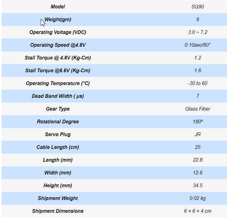
Servo Motor Specifications
Linear Motion Actuator Assembly:
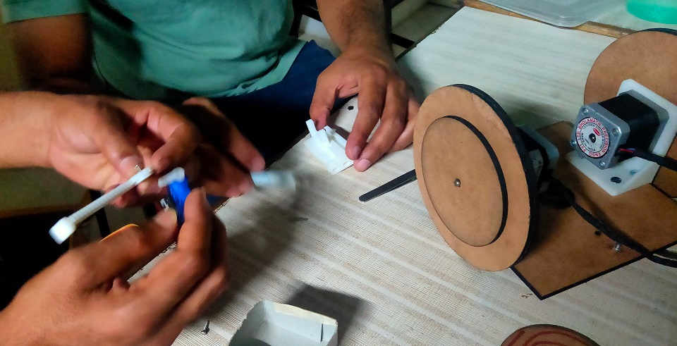
While conducting the first trial of our Concept, I have made the Z Axis with the help of Foam and inserted the Peninside it through a Hole and clamped it with the Servo Motor Horn. But it was a temporary arrangement. I found out that the Prn was inclined and bend inwards. Also, the Servo Horn would lift the Pen sideways. I figured out that, I would need a Linear Motion Actuator for our Z axis to function. Also, the Pen was to be installed in the Center of the machine. SO, it had to move upward and downward only.
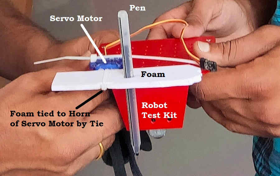
First Z Axis on Robot Test Kit to test the Concept.
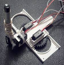
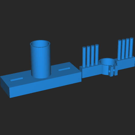
Then, I searched for the various mechanisms and landed on the page of Thingiverse where the Linear Motion Actuator of Servo Motor was available for download. I downloaded the parts and 3D printed it to conduct some test runs over it. It could be then modified as per our need.
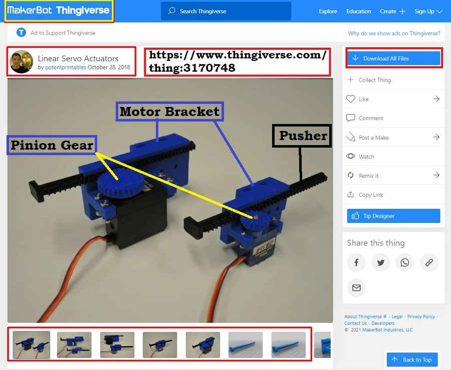
Linear Motion Actuator for Servo Motor on Thingiverse
 Servo Motor Bracket | 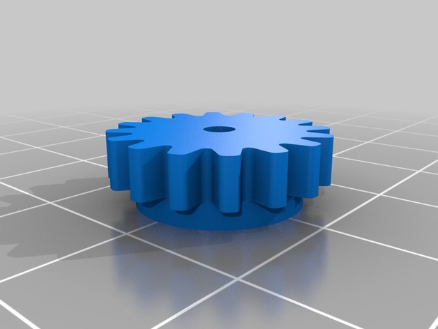 Pinion Gear | 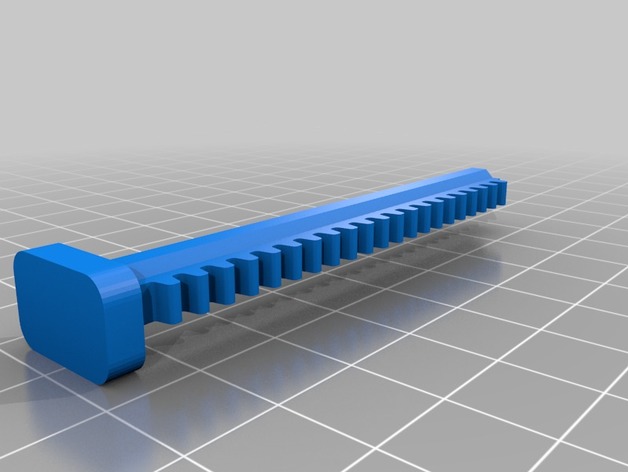 Pusher |
|---|
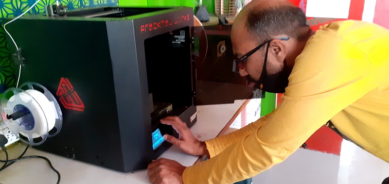
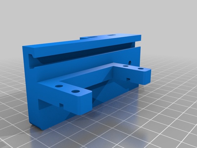
3D Printing the Z Axis
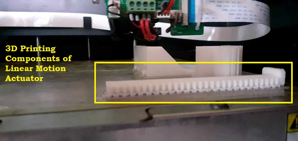
3D Printing the Components of Linear Motion Actuator for Servo Motor
Joining the Bracket, Pusher and Gear to our Servo Motor Mini SG-90
Clamp like Assembly to hold the Pen (Z Axis in Place):
After conducting the trials on the Linear Motion Actuators, I had to figure out the Mechanism to hold the Pen in place. Few Challenges were -
- Stability: The Pen had to be Stable and should not bend or incline.
- Flexibility: The mechanism should allow the Pen some Shock Absorption in case if the Servo pushes the Pen down more than required or even with more force.
To resolve these issues, I decided to clamp the Pen on two points - one at the Top and the Other at the bottom. This would give the Pen required Stability. I decided to use Springs to provide Suspension / Shock Absorption to the Pen. The drawings have been already shared earlier on this page.
The first idea clicked from the design of FAB Academy 2021 - Mohit Ahuja's Flexure design of Nose, Eyes and various Numbers from the Computer Controlled Cutting Week. I also referred various Z axis assemblied done by other students of FAB Academy in the previous years and I came across the design of Adrian Torress. I decided to use this in my machine. So, I took the reference and designed for our Z axis assembly. We have also used his design of Castor wheel in our machine.
 Clamp and Top Pen Holder | 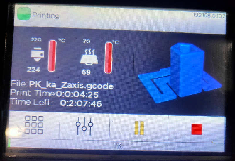 Adrian Torress's Design designed and modified by me |
|---|
 Trying Spring Mechanism | 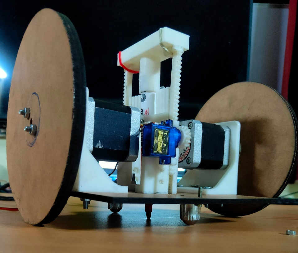 Assembled the Z axis for Trial Test |
|---|
Video of First Test of Z Axis:
Here, you can see that the Z axis is getting jerks because of the sudden movement of Servo Motor. We need to change the Speed by changing the Angle of the Servo motor by changing the width of the pulse for smooth transition/movement. Also, the lower clamp is suspended in between and not able to fix at the bottom due to mistake in measurements. The base of the Motor bracket is not allowing enough space for the clamp to be fixed at the bottom of the platform. Also, the assembly is tied with the Rubber bands. I had to make holes or design it as a whole. The assembly is also inclining towards the right side due to uneven pressure or may be due to the friction between the pusher and the slot of bracket. I will have to file it evenly.
Video of Second Test of Z Axis:
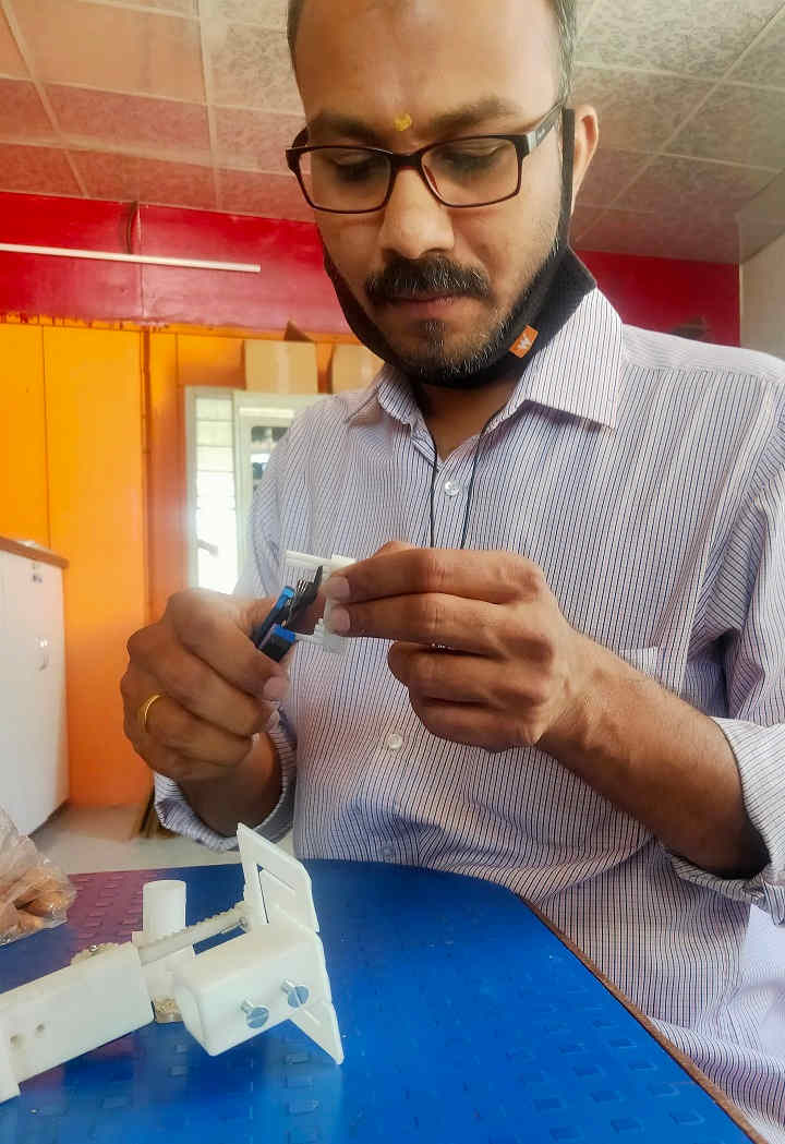
After discussion with other group members, this idea was dropped and search for more suitable solution began. I then again thought of the same design of Adrian Torress and thought of using it. I just made the Pen holder more longer than his design and made room for attaching this assembly to the Pusher of the Motor. The clamp can be used at the bottom with ease. I just needed to remove the extensions that I have kept for the Springs to be attached. The Flexure was working fine.
I kept the thickness of the Spring very Low (0.5mm) to provide more suspension but to my surprise, it became too much flexible and was vibrating while the movement.
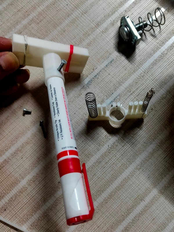
This assembly for the Z was finalized with modification in the thickness of the Flexure pad. I then increased it to 1.5mm and 3D Printed. The Pen was Stable and supported in the bottom by the clamp and was having straight movement as we can see that the Pen inserts in the clamp.
 Cutting the Extensions of the Clamp | 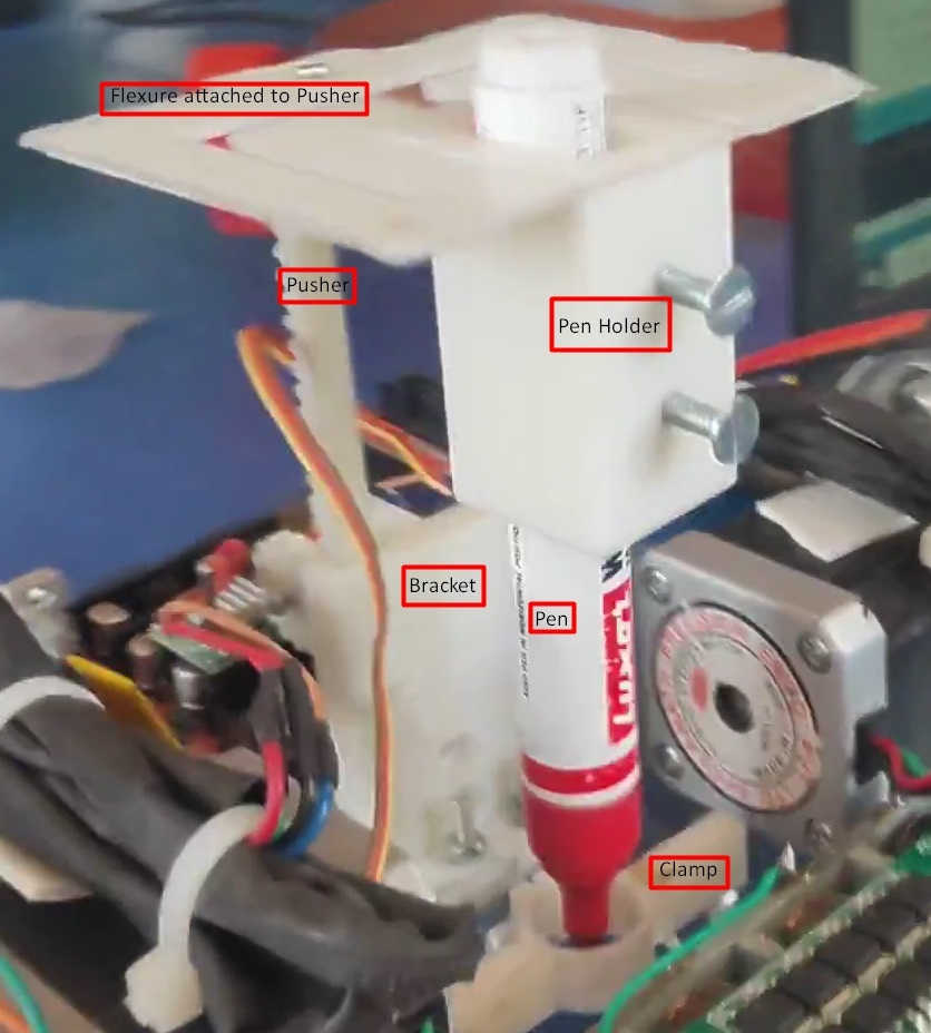 Assembled the Z axis for Trial Test |
|---|
Chitra-CAR
Summary:
In this week,
- I understood about the Actuation, Mechanical and Automation mechanisms in the Machines.
- I designed and assembled the Z axis assembly of our Machine.
- I documented the Group Assignment of this week.
Downloads: Original Files
The Original Files of Z-Axis assembly could be downloaded from here.