


About Final Project:
GoatIT - Smart Weight Measurement and Management System
Objective:
To Plan and Sketch a Potential Final Project (Product)
Most of these above mentioned Questions have already been answered and addressed in the previous assignment of Applications and Implications.
Learning Outcomes:
- Create your own integrated design
- Demonstrate 2D and 3D modelling capabilities applied to your own designs
- Select and apply appropriate additive and subtractive techniques
- Demonstrate competence in design, fabrication and programming of your own fabbed microcontroller PCB, including an input and output device
Checklist:
- Made your slide: 1920 x 1080 pixels with your name, project name, Fab Lab name, a photo/render/sketch of your project, a brief description of what your project is/does ✔
- Made a ~1 minute (10MB/1080p) video of you explaining your project ✔
- Made a separate Final Project page that briefly summarises your project ✔
- Included the BOM (Bill of Materials) for your project ✔
- Linked from this page to any weeks that you worked on your final project ✔
- Linked to your presentation.png and presentation.mp4 ✔
- Included all of your original design files in the archive (2D and 3D, board files and code). No external hosting of final project files - discuss file sizes with your instructor ✔
- Included the license you chose ✔
- Acknowledged work done by others ✔
Opening Quotes:
(Precisely explains progression of my state of mind)
- "A mind forever voyaging through strange seas of thoughts..."
- "You can’t follow your Heart when it is more confused than your head…."
- "Indecision and delays are the parents of failure."
- "Action cures fear. Indecision, postponement, on the other hand, fertilize fear."
Introduction:
I am not a person who has original ideas or a nature of observing things and environment to make them better. I thought that whatever needs to be invented is already done. I went on with certain ideas after exploring internet and looking around; asking friends and familiars.
Out of many Project Ideas that I thought of from Gas Sensors for Manual Scavangers, Digital Weighing Spoon, Digital Milk Can, Sound Pollution sensing and increasing the Traffic signaling timer to Goat Health Management System, I decided to pursue my Final Project on Weight Measurement and Management System for Goats (goat IT).
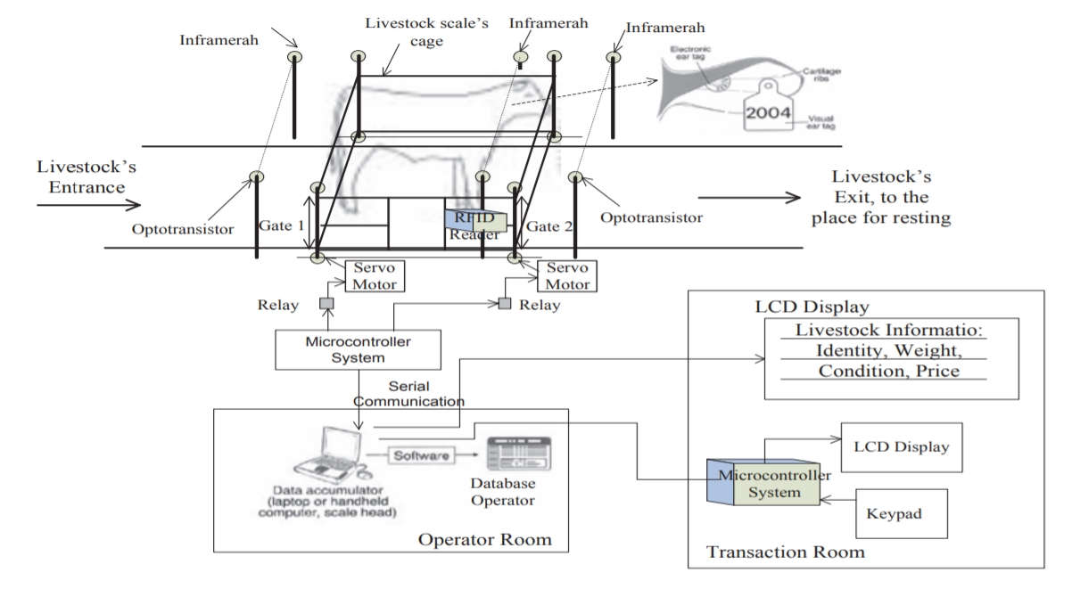
Reference Image from the referred Research Paper
Foreword:
My Project is Smart Goat Weight Measurement and Management System. I prefer to call it "GoatIT" - Application of (IT) Information Technology to measure and monitor the Weights of Goats with respect to FCR (Feed Conversion Ratio) / Link2 to manage the Growth and Profitability.
Body weight information of livestock animals is significant for trade, routine animal health monitoring and dosage calculations for treatment of diseases.
The answers to the following questions will give an indepth overview about my final project.
I selected this project out of many Ideas that popped up due to certain reasons.
Vidarbha region of Maharashtra is known infamously for Farmer suicides due to scarce rains and inproductivity. An allied/supplementary business of Goat Farming could help them to sustain. Only thing is to do the Goat Farming scientifically.
The commercial weighing scales and machines available in the market are very costly. I wanted to bring the the price of these weighing balance in the grasp of the farmers.
Also, the data log on the server will notify the farmers about the options to sell or hold or pay attention to a particular goat (Doe or Buck).
WHY this Project?
Vidarbha region of Maharashtra is known for Farmer Suicides. This is because of reliance on only one source of income mainly farming which is affected by uncertainty of environmental conditions, diverse rain pattern - sometimes scarse or too much causing loss of crops.
Goat Farming is a lucrative option to supplement the agricultural farming and farmers of other regions (Marathwada, North Maharashtra) of Maharashtra are doing it profitably because of applying scientific methods like measurement of FCR, track of development and health by sensors, vaccination status etc.
Vigyan Ashram is also having the Goats and they provide Scientific Solutions directed towards the Rural Technology to the needy. They were already conducting certain experiments about the Nutrition, FCR (Feed Conversion Ratio), Data Maintenance for monitoring the Health Status, Pregnancy, Vaccination schedule, Weight Gain, Growth of the Goats in their Farm.
But, I noticed that the Weight is taken on Hanging Type of Weighing Balance and the Data is maintained in a Rough Notebook. They have enquired about the Balance and it was going to cost them 13,000 INR.
So, I decided to pursue this project. But, considering my competence in Mechatronics, I decided to limit my Final Project to building a Weighing Balance and maintaining the Weights of the Goats. Later, in the next spiral, other sensors like temperature, heartbeats and events like vaccination, pregnancy could be added.
Goat Farming business is growing because of various reasons–
- - High Nutrition
- - Less Investment
- - Growing Demand of Goat meat
What is FCR?
Reference: Animal Care Practice-Folio3
The amount of crops/feed that is required for the production of a unit of meat is known as Feed Conversion Ratio (FCRs) and they are discussed in the aspect of efficiency.
FCR is a mathematical relationship between the quantities of feed provided (fed) and the weight gained by consuming it. It can be calculated by dividing the total input of the given feed by the total weight gain.
F.C.R = Input of feed / Weight gained by the animal
The feed conversion ratio for goats On the high concentrated feed, goats have an average FCR of 4.5, 5.5 on good-quality forage. And on straw ration, 30. FCR tends to be higher for older lambs (e.g. 8 months) than younger lambs (e.g. 4 months).
Goat Weight Measurement and Management System (Goat IT):
"Goat is the Poor Man's Cow"Problem Statement:
Goat Farming in many areas is unorganized. Goats are identified in a flock based on their color, horns, size etc. for recording (in a notebook manually) their weight, health status, nutrition, vaccination schedule, milk yield etc.
Issues-
- Weight could not be documented properly
- Goats cannot be differentiated and identified easily
- Still, the documentation is done in the notebooks manually.
- Farmers rely on their experience and extpertise to assume about the health status of the flock
Solution:
- My Goat Binder
- go360 Bio Track by Agsights are already available solutions in the American market.
My idea is to fabricate a System which would
- - Give QR codes to the goats
- - Which when scanned, will be able to record weight, temperature, heart-rate, vaccination status, nutrition etc.
- - Which would be then sent to the cloud
- - Where a datalog will be created
- - and retrieved for proper maintenance of the goats' health.
- -Create and Provide data log for monitoring, retrieval and usage as needed
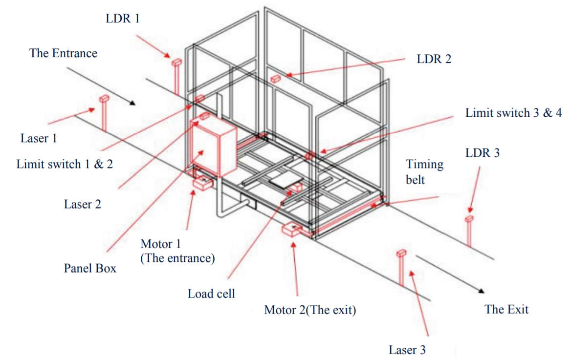
Reference Image from the referred Research Paper
Benefits:
- This would enable the Goat Farmers -
- -Inexpensive Solution as the Commercial Weighing Balances cost from 6.5K to 25K INR.
- -Integrated with Analytical Information: Cloud based integration will allow the use of weight collected for analysis and FCR calculations to track the profitability
- -Mobile: The assembly could be moved anywhere and installed with ease.
- -Convenient Data Log for easy access (on Mobiles), monitoring and studies.
- -Could be also used by the Customers to know about the quality of their goats meat
Possible Difficulties:
- -Goats eat the QR codes generated from Paper or any other edible material of themselves or of other goats
- -QR codes generated from heavy material and pinned to their Ears may affect their Selling Price in the market, may fall off the eard due to erosion
- -Making them stand calmly on the weighing balance platform
Limitations:
I will restrict my fablab project to measuring the weight of the goats on daily basis and display it through a output device and simultaneously sending it to cloud.
In Spiral development, all the sensors may be joined and complete health data of goats can be maintained.
Tools, Softwares and Machines I intend to use for this Project:
- Laser Cutter and Vinyl Cutter for Cutting and Engraving the QR Codes
- Plasma Cutter for making the Cage like structure on the Weighing Balance
- 3D Printer to print the Outer Case / Shell for the Electronics Circuit and Handle Bars used in the Structure
- 3D Design Software for Designing the Structure
- Input Devices (Load Cell Sensor, RFID Sensor); Output Devices (LCD/LED Display)
- Interface and Connectivity (Apk Development and Cloud integration)
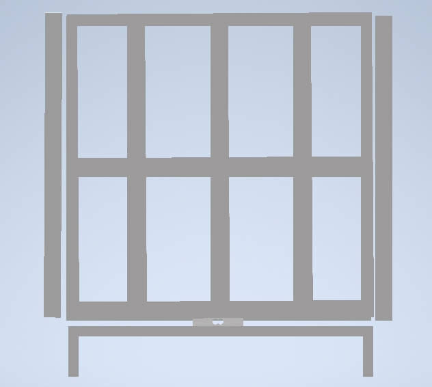
Initial Sketch of my Proposed Project:
Link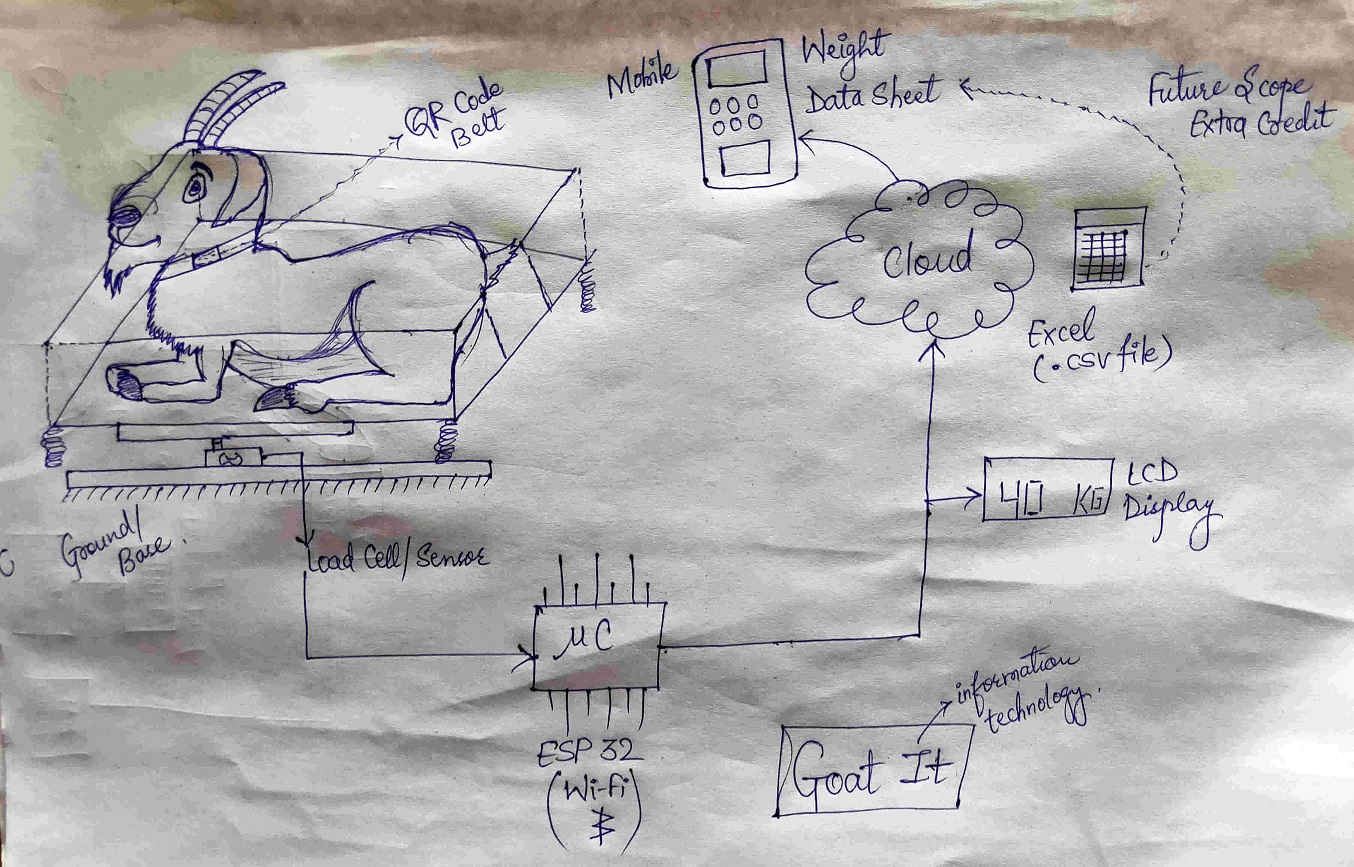
What will my Final Project "GoatIT" Do?
My project will be able to help Farmers in multitude of ways. The Flow of the activities in my project is as follows:
- The goats will have RFID tags attached to their necks through a band and the goats will be differentiated based on their RFID numbers
- The goats will approach the Weighing Balance placed at the entrance of their cage.
- The RFID tag reader will read the tag and send the information to the Server
- Goat will stand on the Weighing Balance
- Weight of the Goat will be displayed on the LCD screen attached to the scale/machine.
- The same weight of the Goat will be sent to the Server and entry would be done in the respective RFID number of the Goat.
- Thus, a data log would be created on the server for the weights of the goats.
- This data could be accessed by the farmers anytime and anywhere and used to make decisions about paying attention or holding or selling a particular goat.
- Basis being the FCR i.e Feed Conversion Ratio - which calculates the Weight gain by the Goats in relation to the quantity of the Feed Input. The weight of the goats increases on daily basis approximately 60 grams and more.
- This weight change could be monitored with the help of my project.
The result of the animal weighing is displayed on the LCD screen and sent to the RFID-based database identification system. Reference / Link2
Who has done what beforehand?
I surfed a lot through google, YouTube, ResearchGate and other platforms to find about Smart Goat Weight Measurement Scale but couldnt find enough references.
Most of the research was on finding the weight of the goat by measuring the size of the girth, length of the goat etc.
Commercial weighing Machines have been made by many and suppliers could also be found on IndiaMart.
One of the Research Papers that I found was having the detailed documentation of Iot Weigh Scale machine for Cattles / Livestock. The Research Paper could be found here.
Few IoT projects done by the Makers Community are-
- Smart Weighing Machine for Remote Weight Measurement and Monitoring on IoT Design Pro Website
- Weight scale IoT by ESP32 on GitHub
- IoT Weight Logging Scale by SFUPTOWNMAKER on SparkFun
- Digital Scale With ESP32 by Fernando Koyanagi in CircuitsMicrocontrollers on Instructables
- IoT Cat Litter Box on Instructables by Igor Fonseca Albuquerque
One of the websites with intensive information about esp32 and IoT is The Internet of Things with esp32 Created by Espressif Systems. Many Projects, Tutorials, Introduction and exploring could be done by referring these resources.
Any Project comprises of the Designing, Assembly, Tests-Trials and Final Application Demonstration
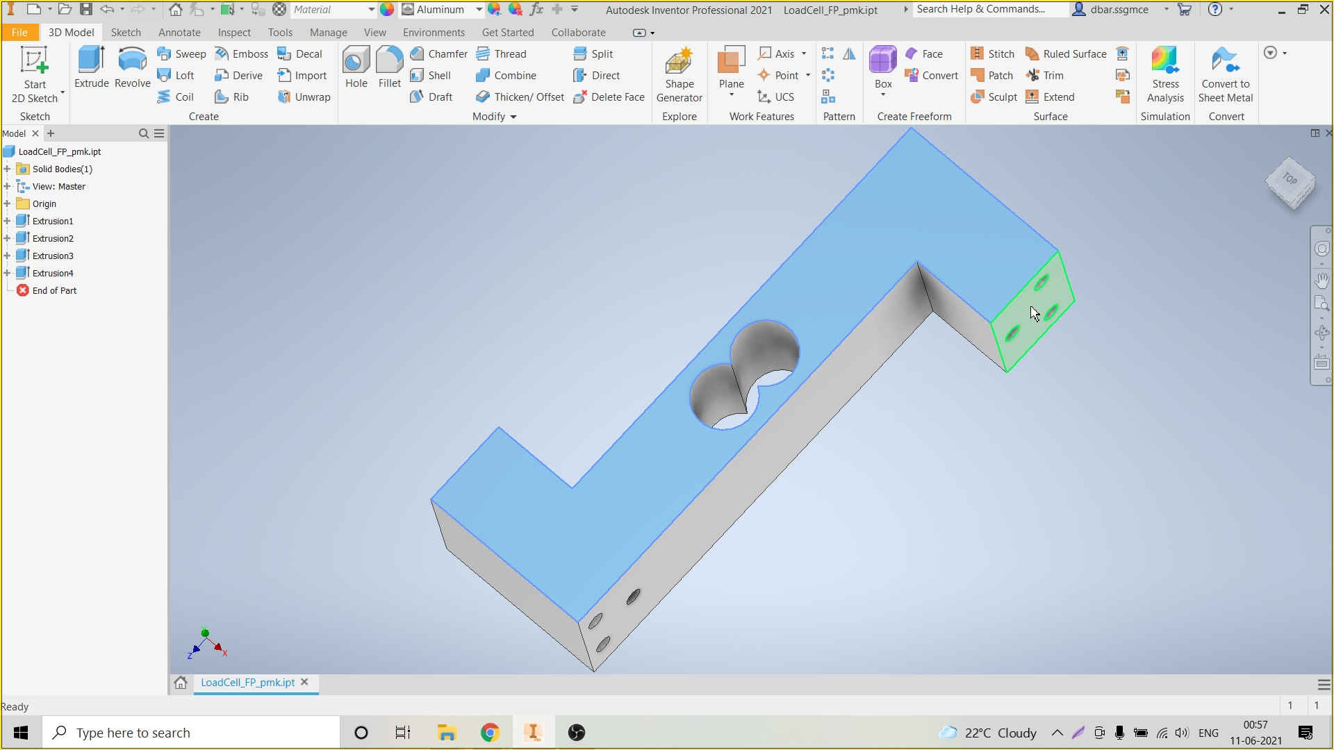
Designing the Components of the Project:
I have designed the following parts and components of my Final Project:
- Metal Structure of Weighing Balance
- Casing for the 16*2 LCD with I2C
- Casing for the Circuit Board
- PCB in Eagle
- Logo of GoatIT
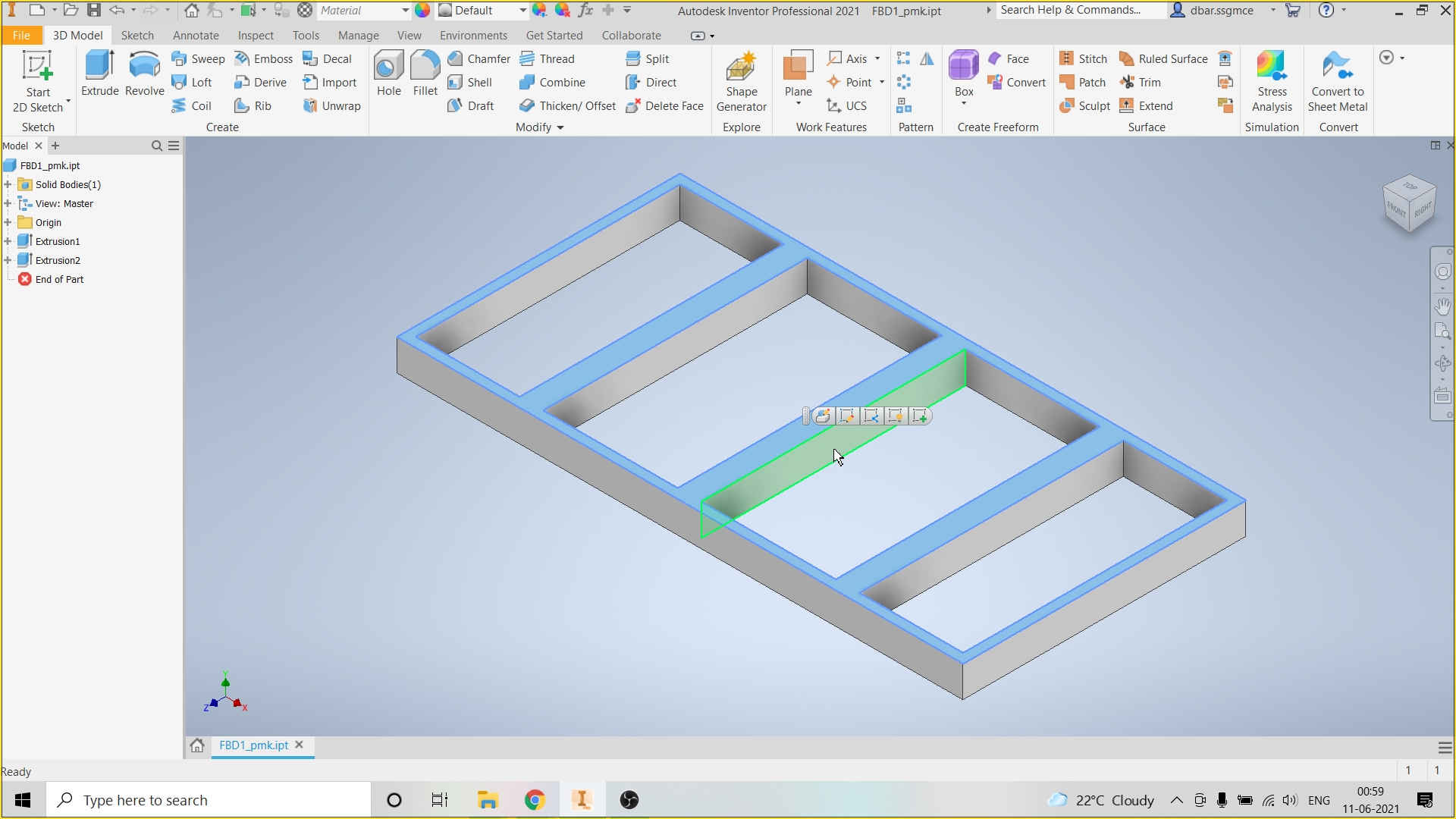
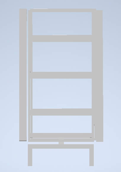
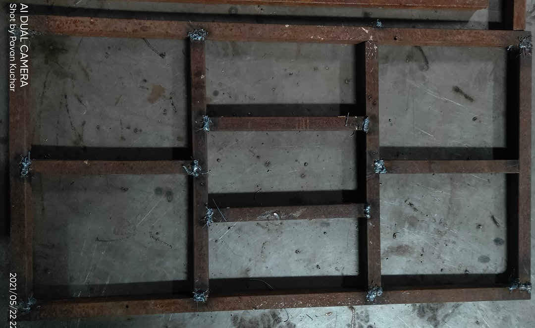
Designs of Metal Structure of Weighing Balance:
Load Cell
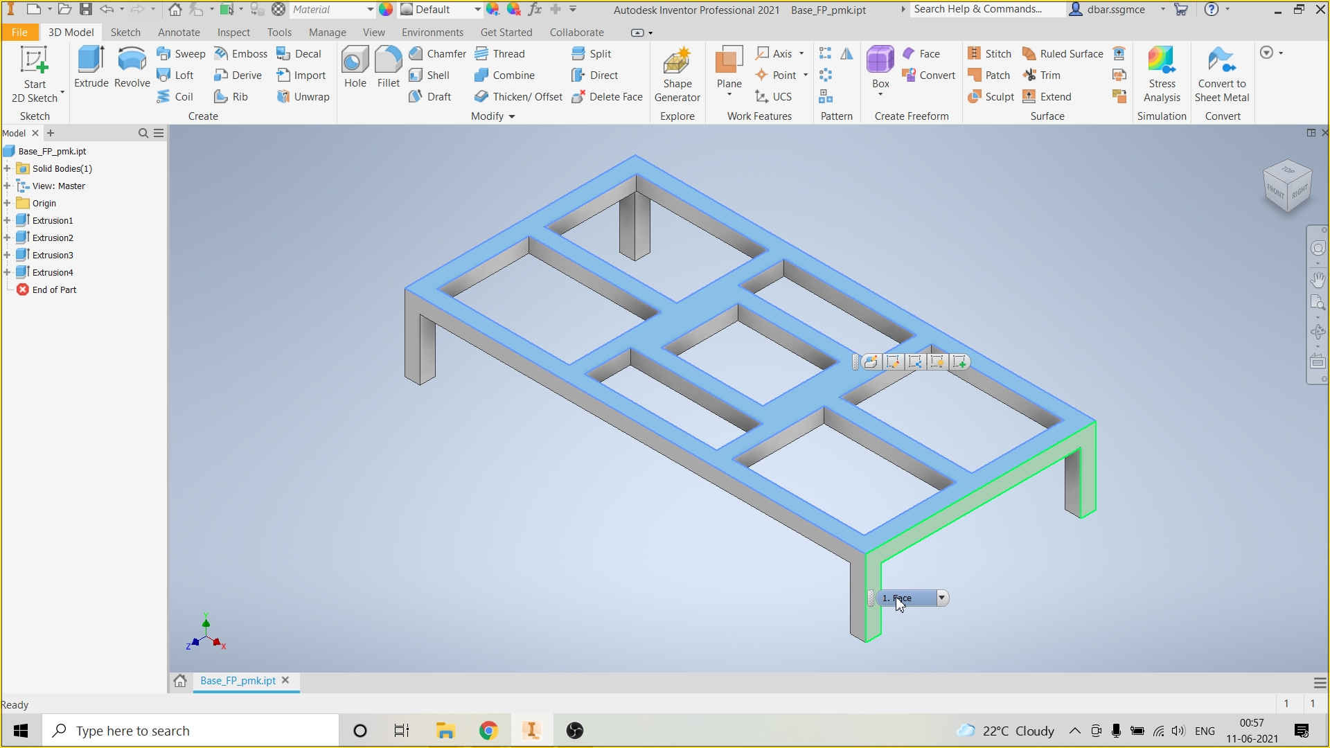
Base of the Weighing Balance
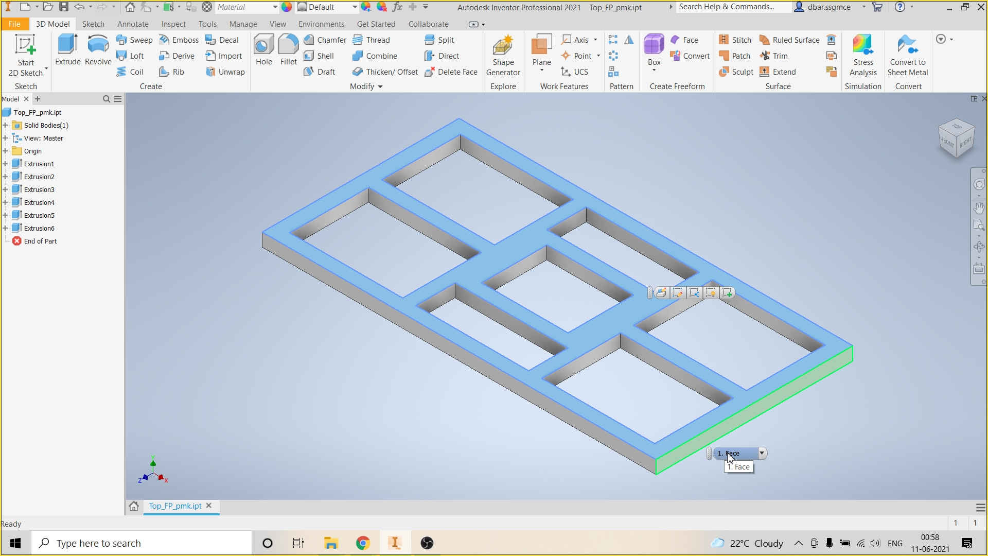
Top of the Weighing Balance
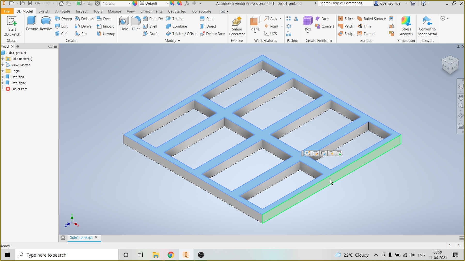
Side of the Weighing Balance
Gate of the Weighing Balance
Design for Plasma Cutting and Welding on the Sides of Weighing Balance
Snaps of the Assembly of Various Parts of Weighing Scale:
 Front View | 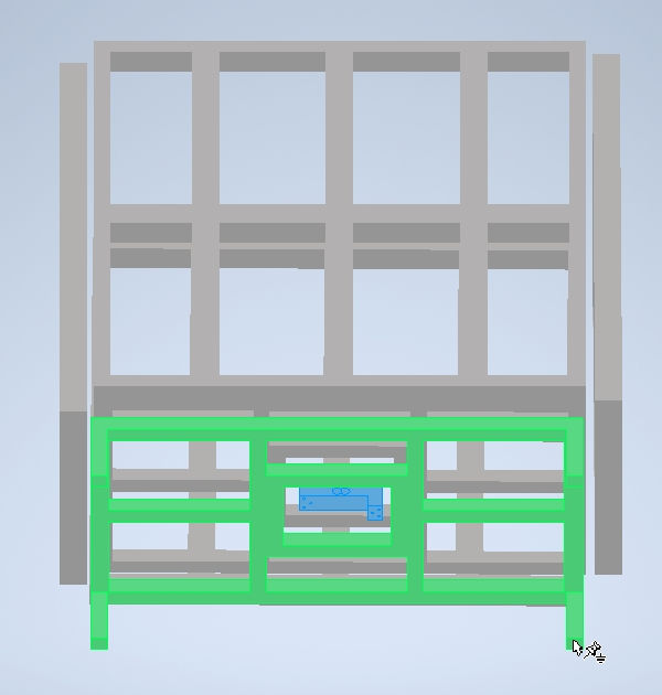 Front Inclined View |
|---|
 Side View | 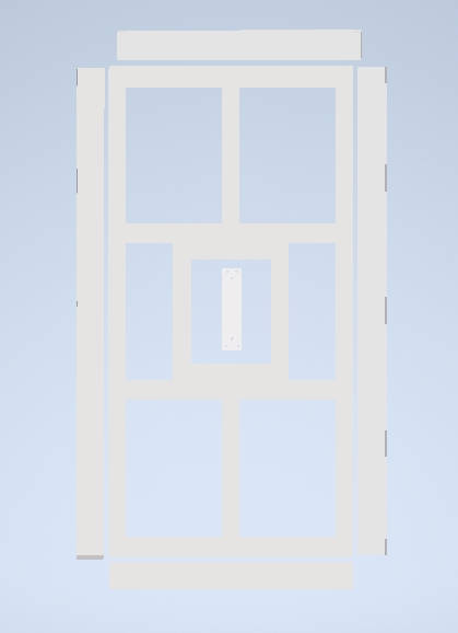 Bottom View | 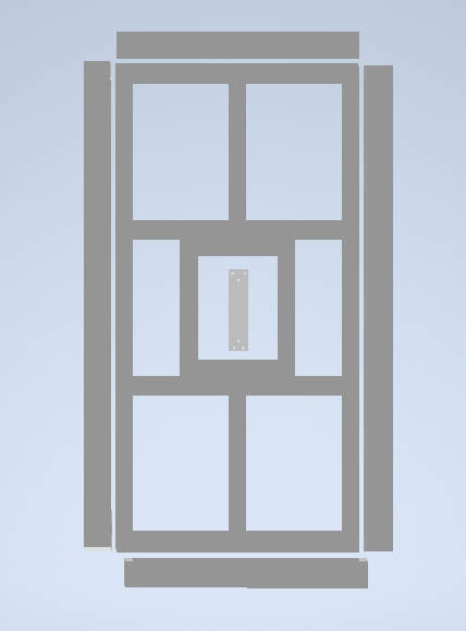 Top View |
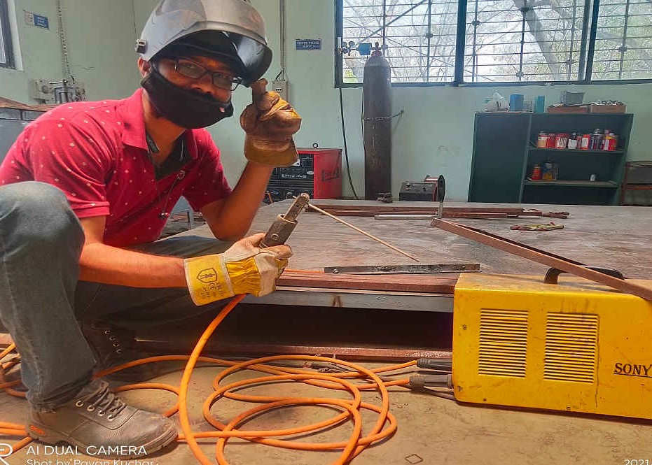
Ready for Welding with Protective Gear
Welding of Base Platform of Weighing Scale
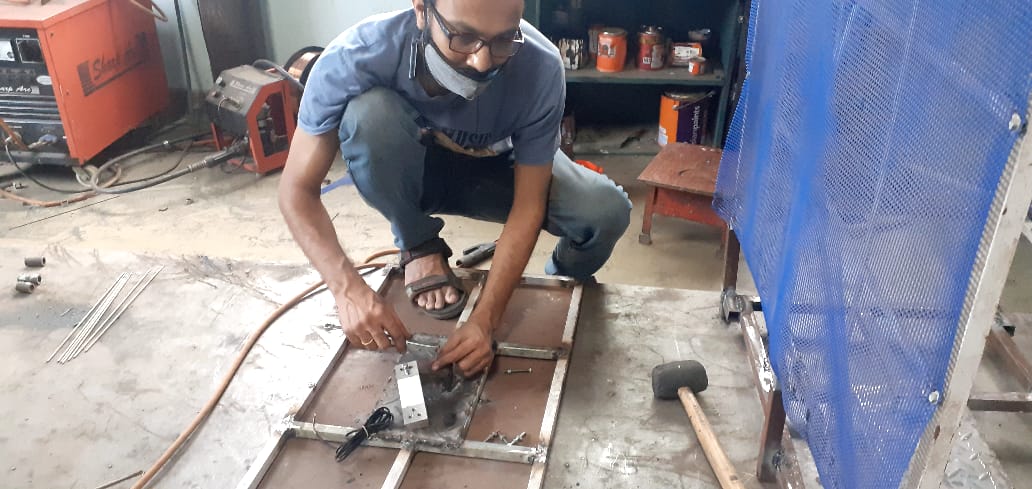
Assembling the Load Cell on the Base Platform
Weighing Scale Ready after Welding with Abhishek
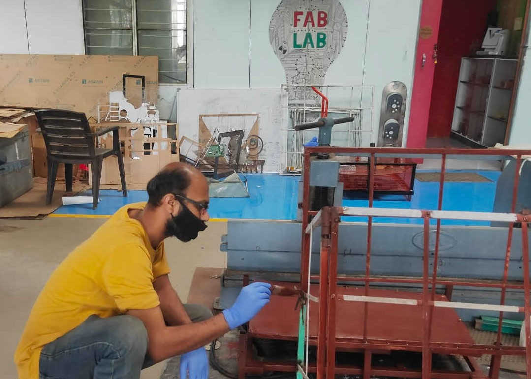
Applying Primer and Paint
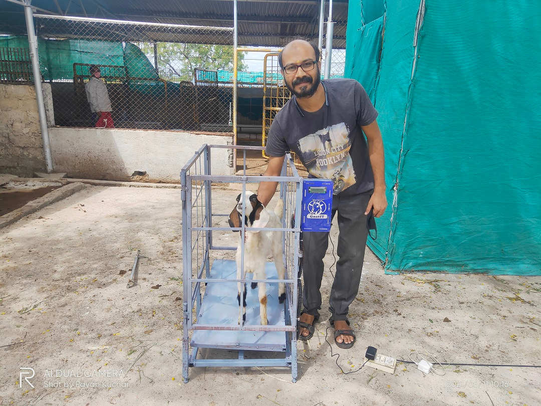
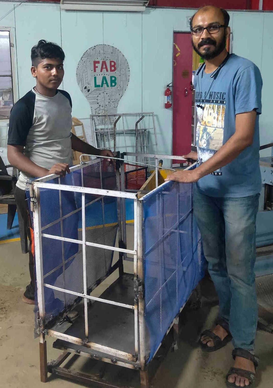
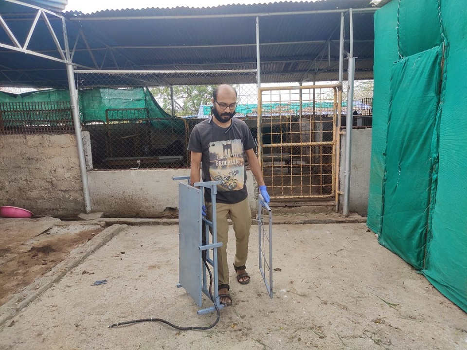
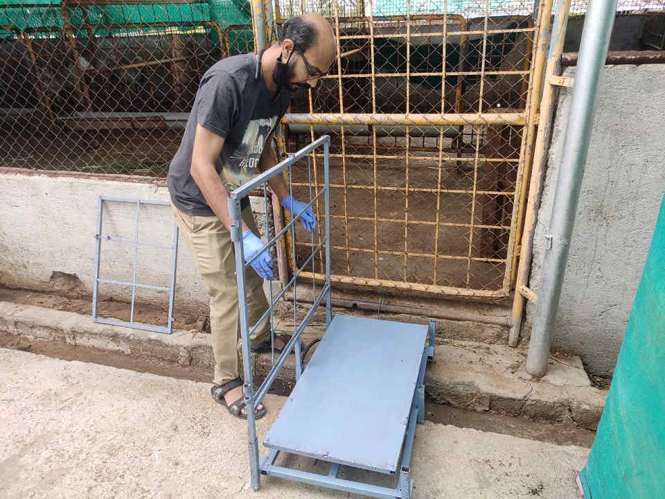
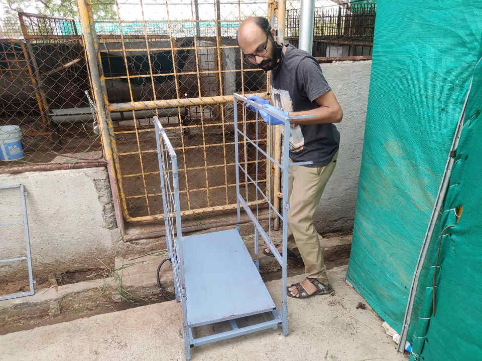
Assembling the Weighing Scale for Testing in the Goat Shed:
 |  |  |
|---|
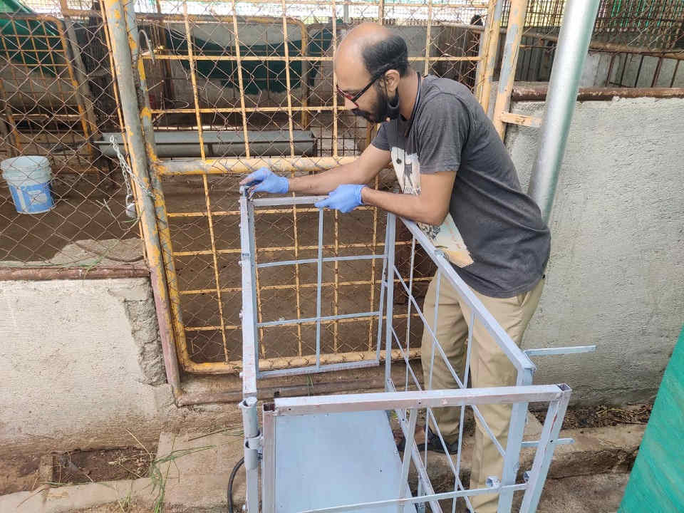 | 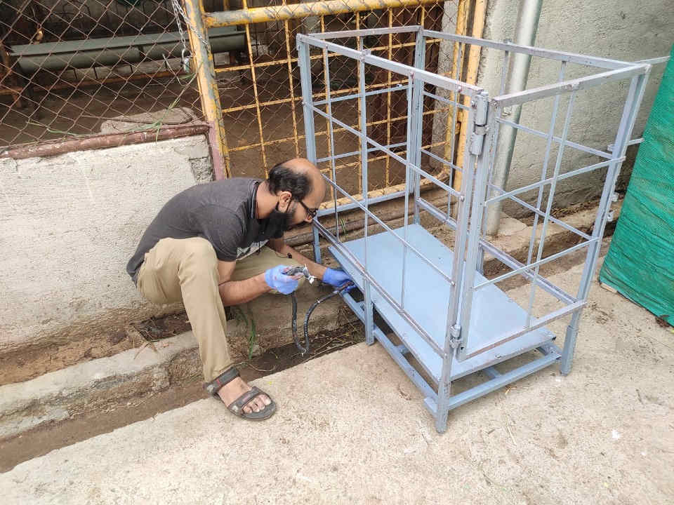 |  |
|---|
ESP32 uC PinOuts:
I was confused about the Pins on which the sensors needed to be attached. Also, I was unable to understand the types of communication protocols. So, I referred this pinout and default pins used by others to make the connections.
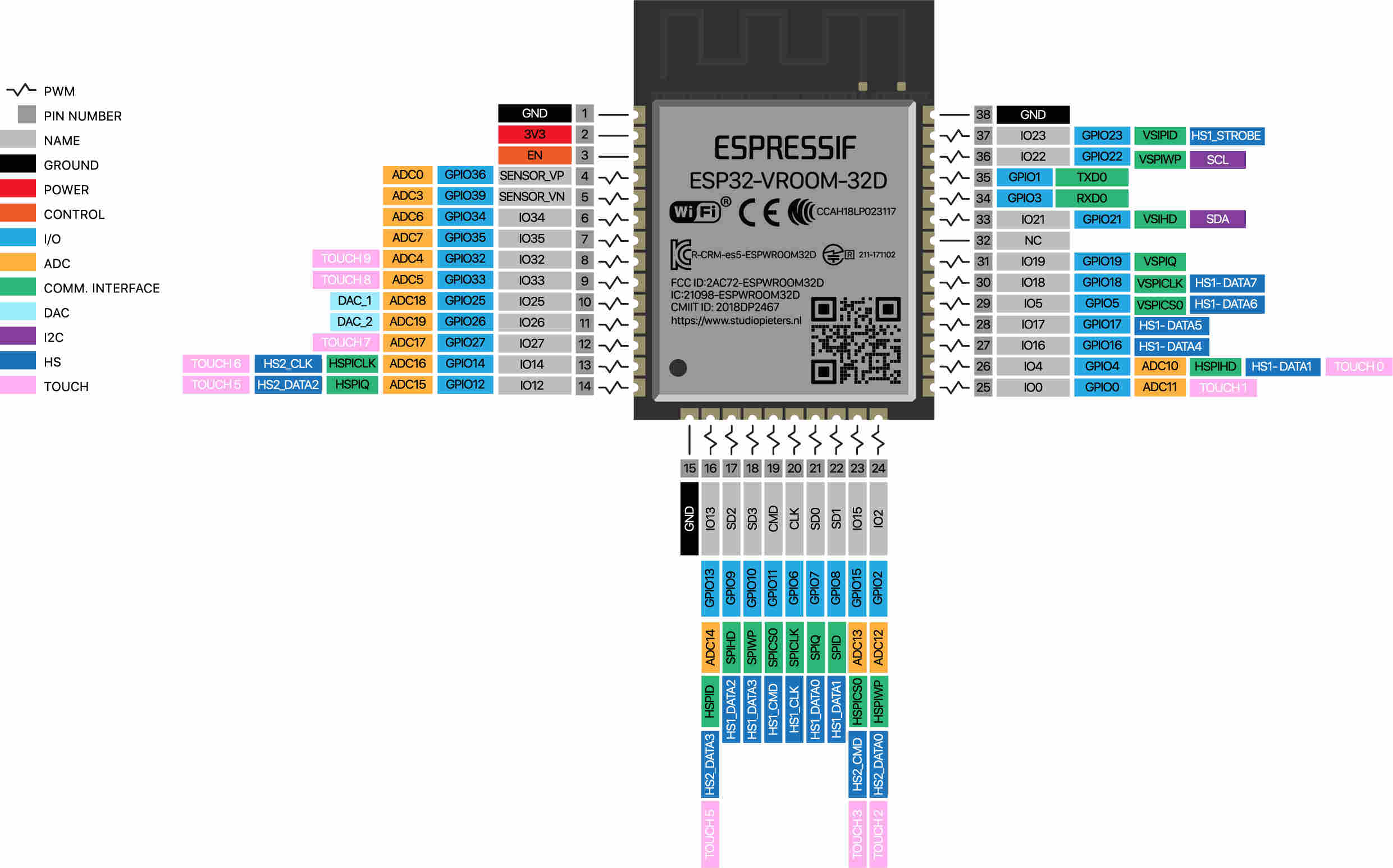
The Pin out of ESP32 for reference to connect the various Sensors (Input and Output Devices)
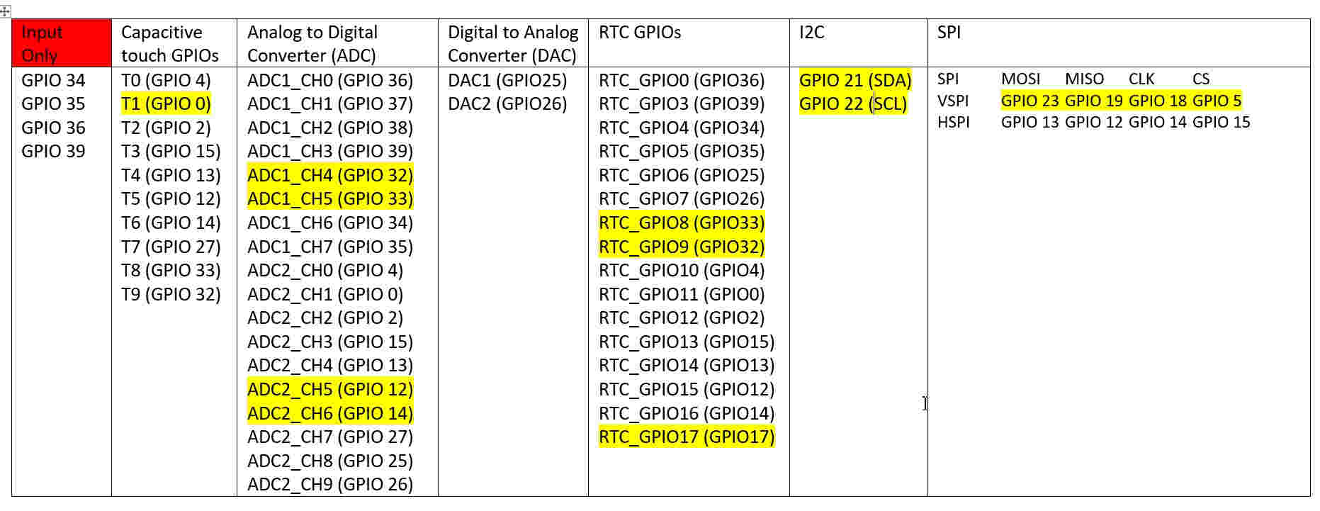
The Pin out of ESP32 for my reference to connect the various Sensors (Input and Output Devices)
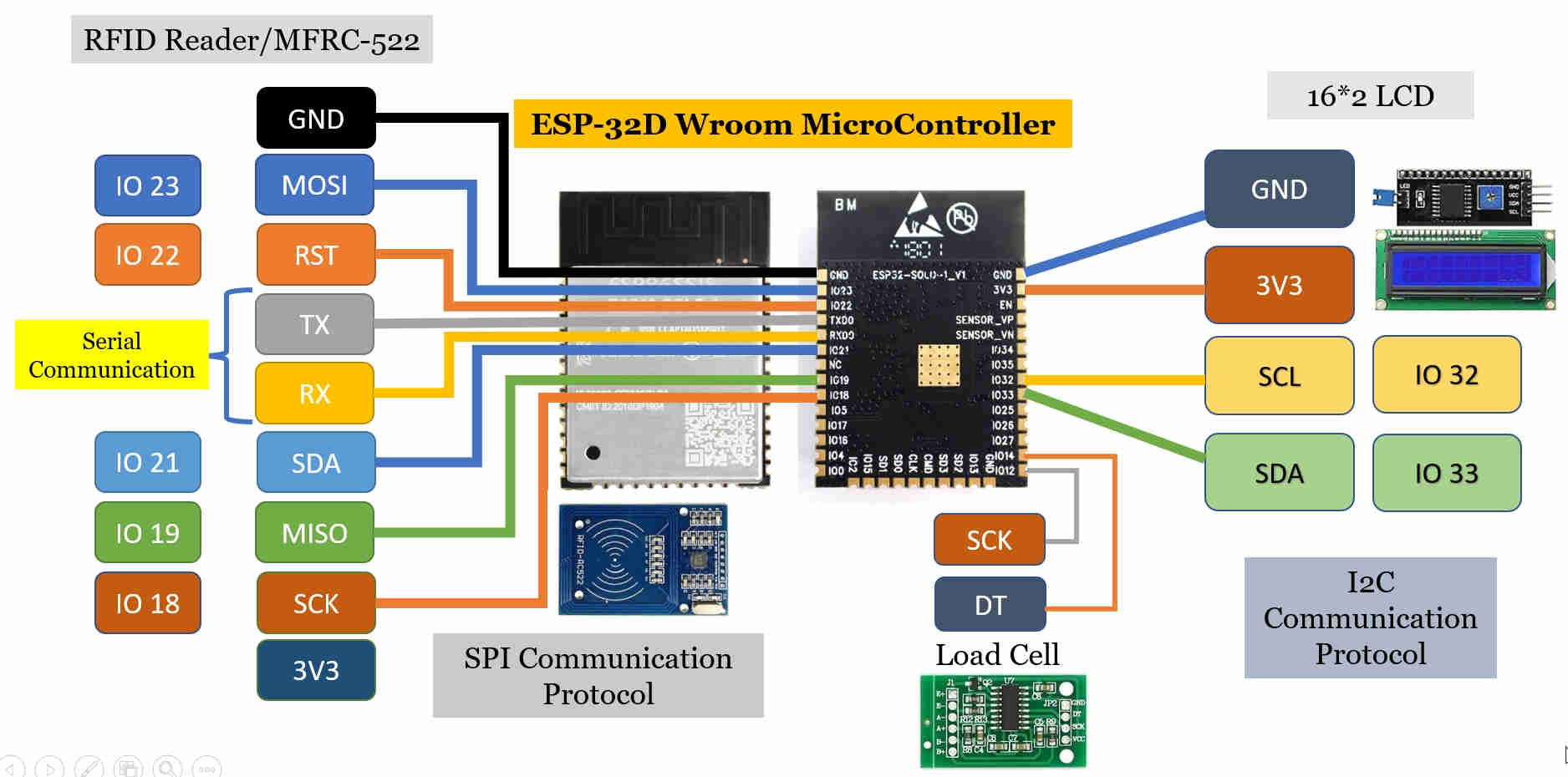
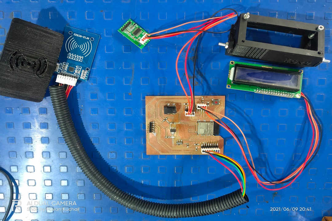
Connections of the Circuit Board among ESP32 and Sensors (Load Cell, RFID Sensor and LCD)
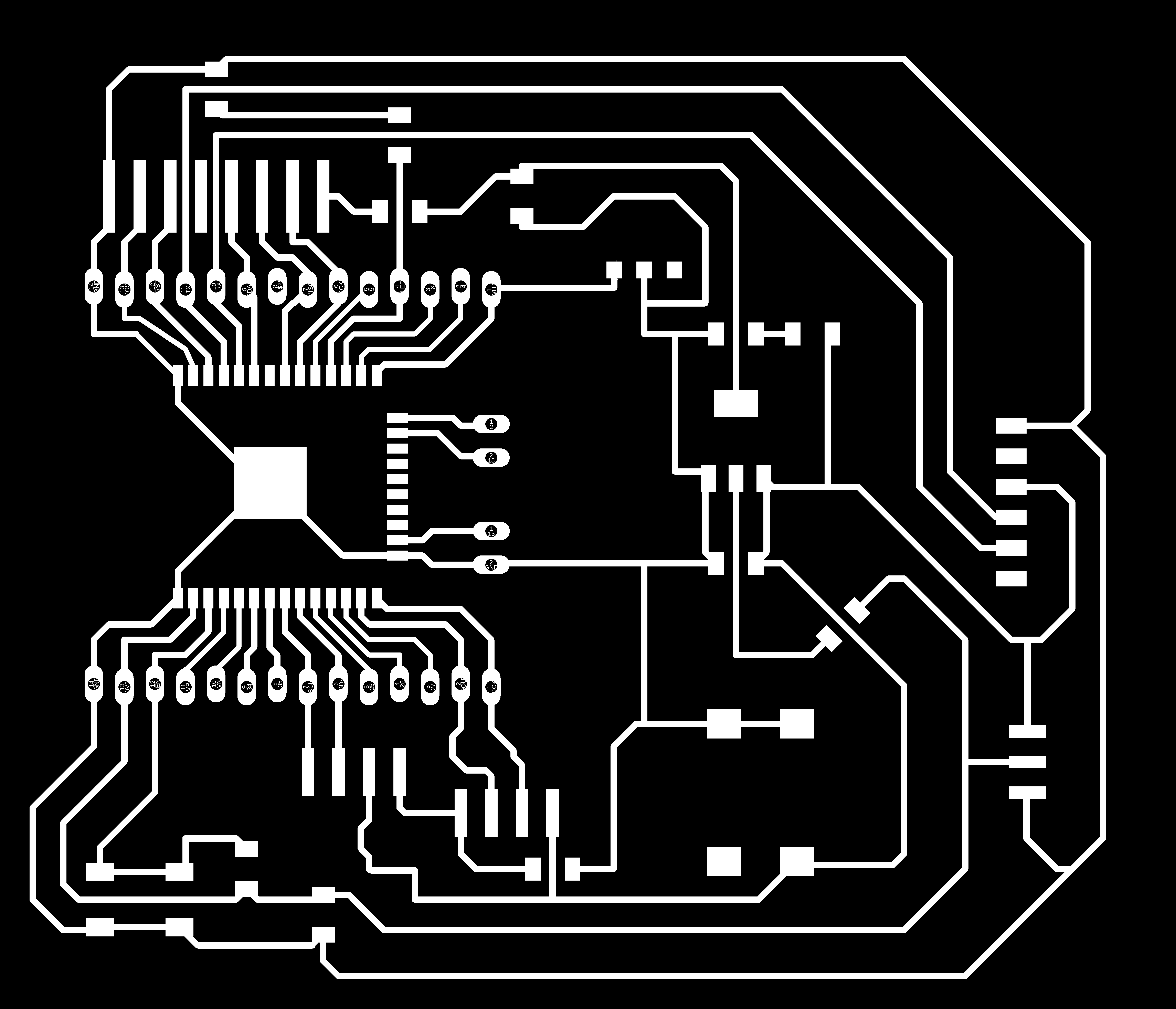
PCB Design:
The Heart of the Project which senses and actuates the whole system is the Sensors, MicroController and the Output devices.
The Final Project PCB was designed by me in the Input Devices Week.
Schematic of the First PCB Board
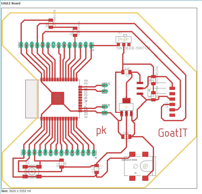
Board Diagram of the First PCB Board
 Milled First Board | 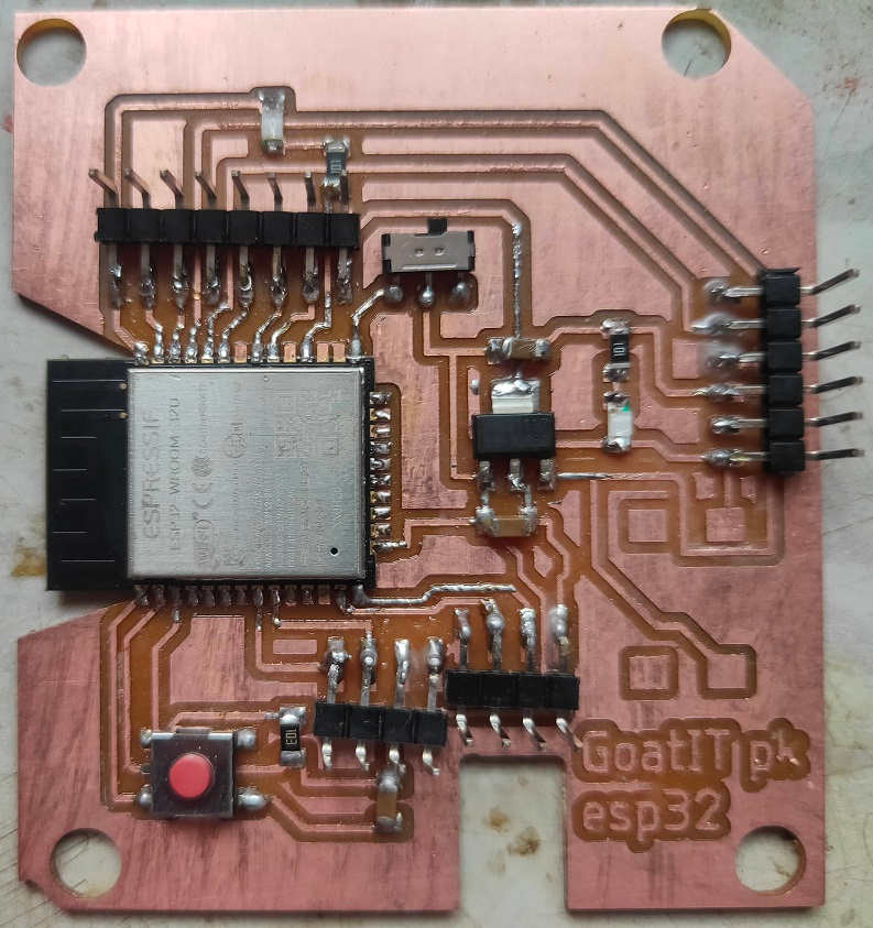 Stuffed and Soldered Components on First Board |
The details about the two Sensors RFID Tag Reader (MFRC522) and Load Cell (HX711) used in the Final Project could be found in the Week 10/Assignment 11 of Input Devices.
Problem:
This Board was functional till the Interfacing and Applications Programming Week, but later on it stopped working. I checked the continuity between the Pins and the Sensors. It was OK. But, after connecting again, the Voltage Regulator became very Hot. I disconnected the Power supply at once but Alas! the MicroController Chip was fried. Ichecked the continuity and it showed continuity between the 3V3 and GND. I felt devastated.
We tried to figure out the reason for the mishap. Even the Board of my Colleague - Anand Tale got fried. We thought that the Volatge Regulator might have malfunctioned and hence the 5V supply might have fried the ESP32.
I then desoldered the ESP32 and soldered the new ESP32 chip over the PCB. It worked well for few days and then the same problem happened with me and Anand.
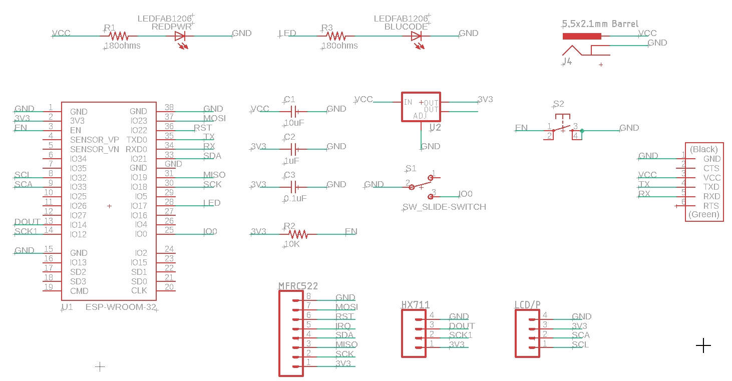
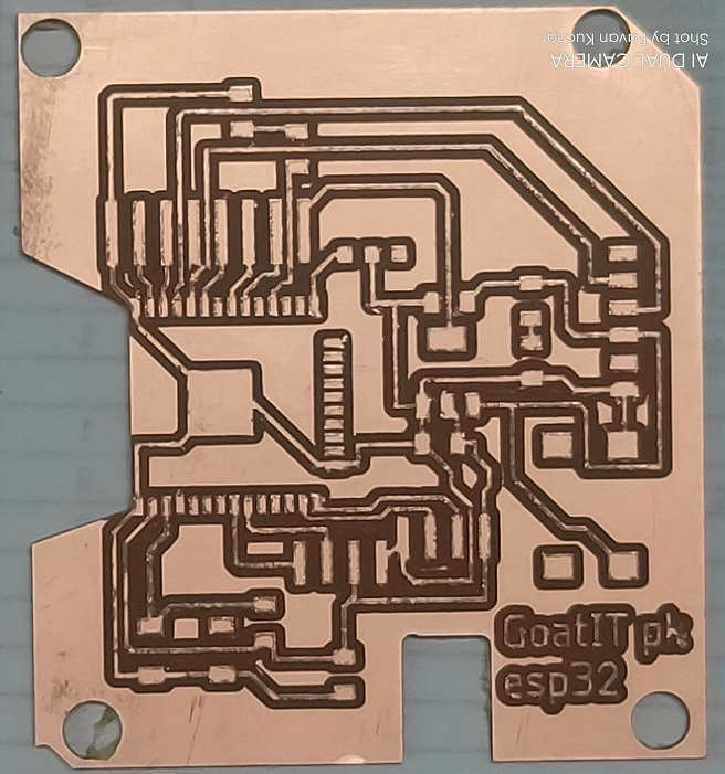
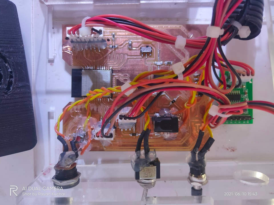
The Older PCB was looking Bad due to heating by Hot Air Gun used for desoldering and so, I designed the New PCB with seperate 5V supply for LCD display (as it required repetetively adjusting the Contrast by turning the Blue colored knob on the Back side of I2C module) and HX711.
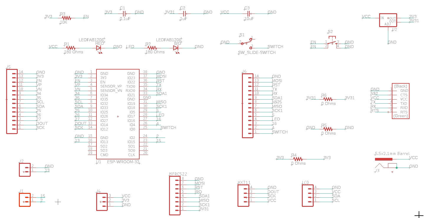
Schematic of the New PCB Board
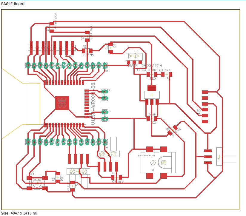
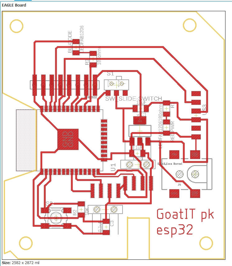
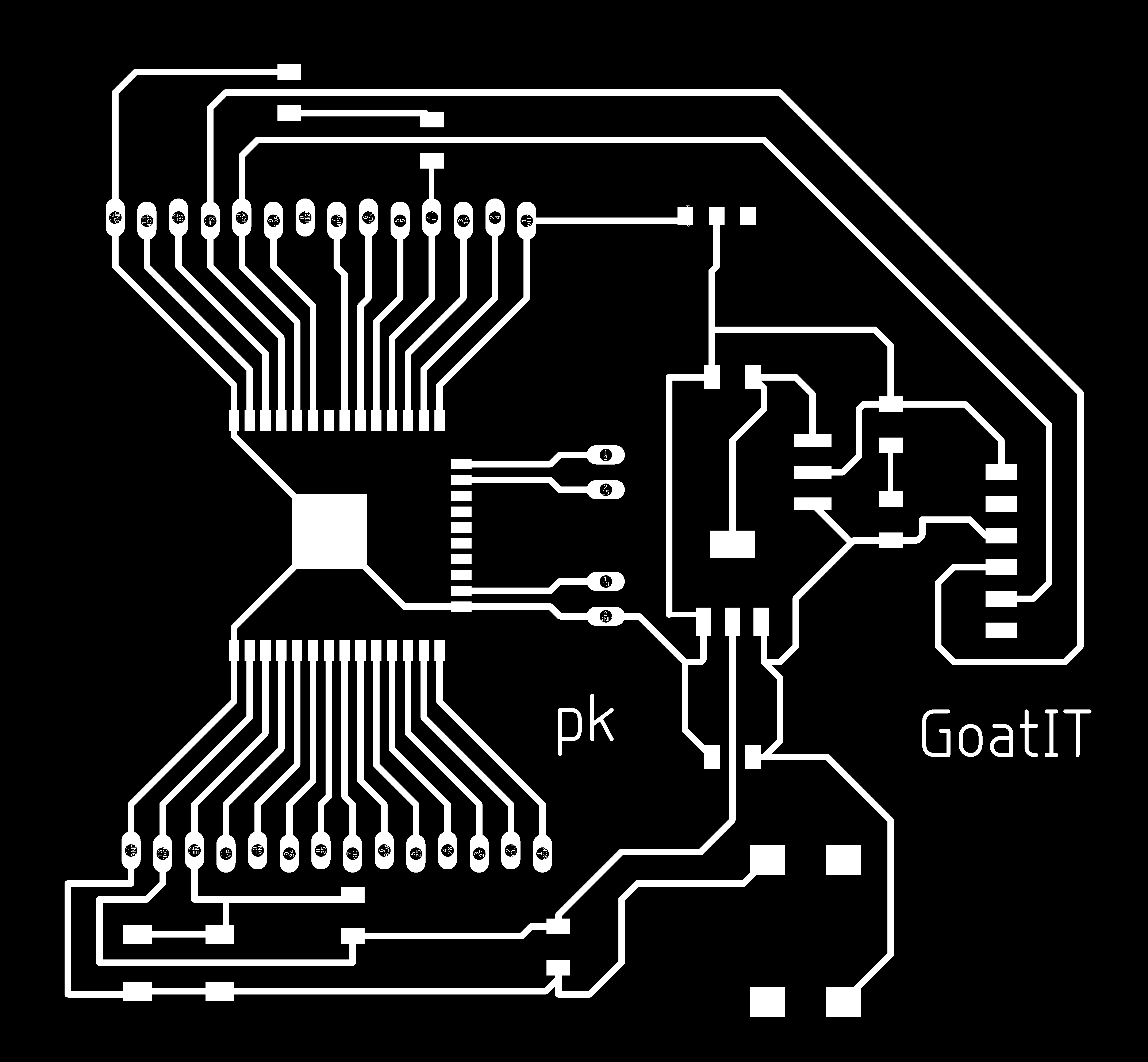
Board Diagram of the New PCB Board
 Traces of the Final Board | 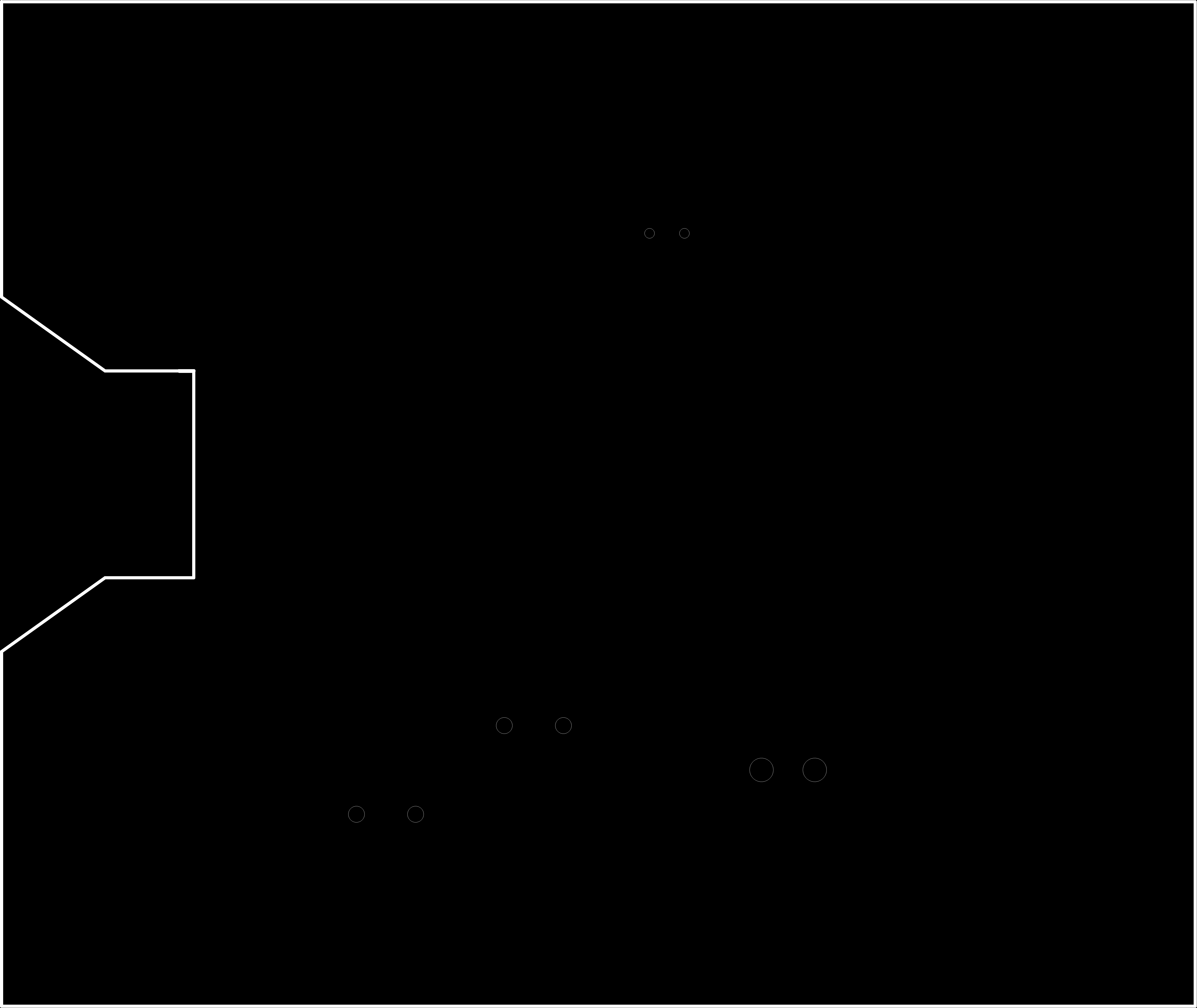 Outer Cut Trace of Final Board |
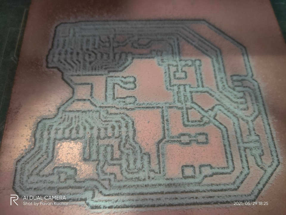 Milled New Board | 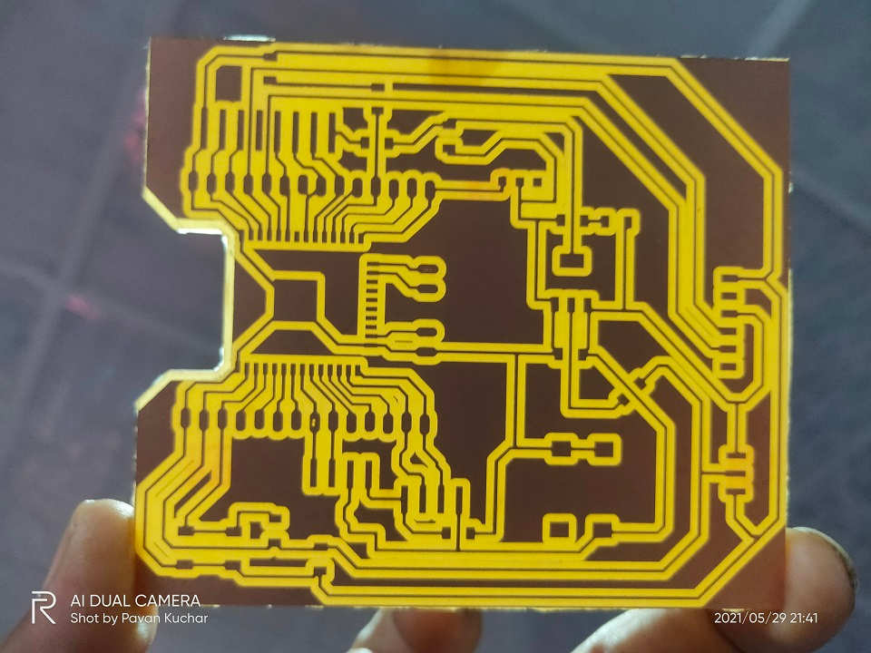 New Board Traces |
I even designed a Simple ESP32 board with connectors pins to be ready for any contingencies. I took the Original design by Prof. Neil and modified it for my use.
Board Diagram of the Plain PCB Board with connector Pins, LED
 Traces of the Plain ESP32 Board |  Outer Cut Trace of Plain ESP32 Board |
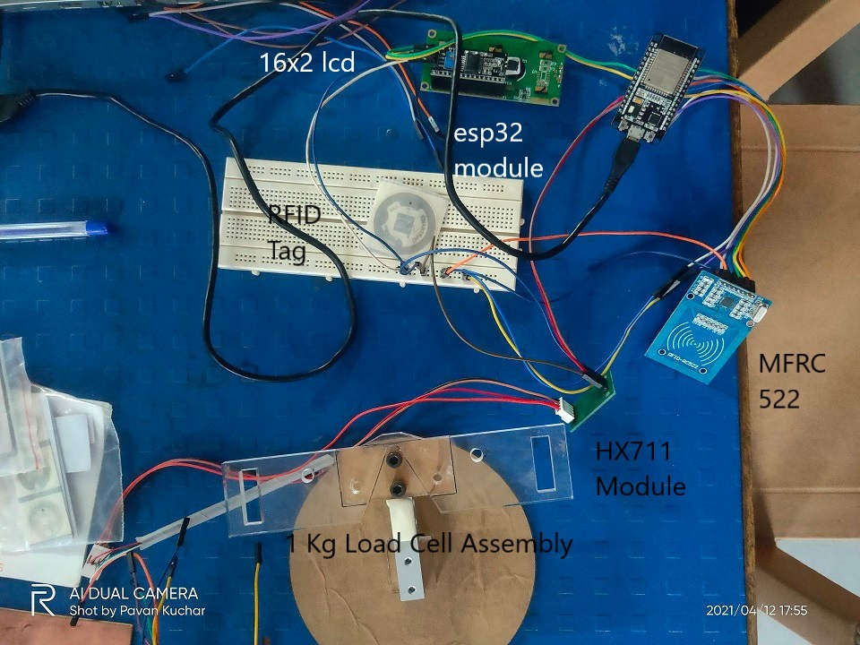
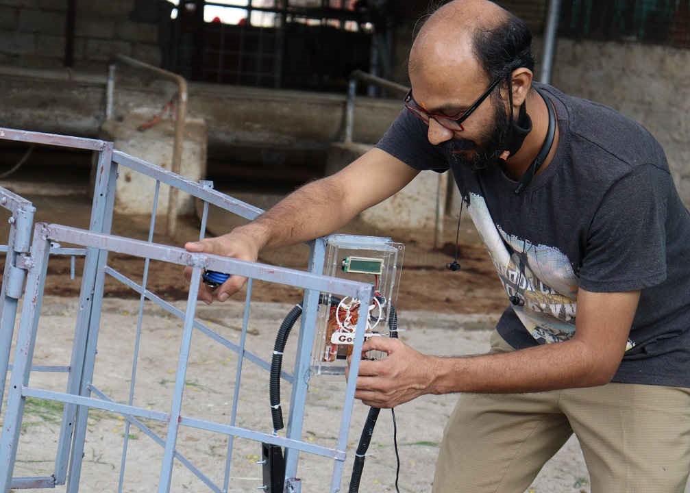
Input and Output Devices attached to ESP32 Module for Testing
Casings Design:
I designed the protective Casing for the 16*2 LCD and the Circuit Board. The Casing for RFID was taken from Thingiverse.
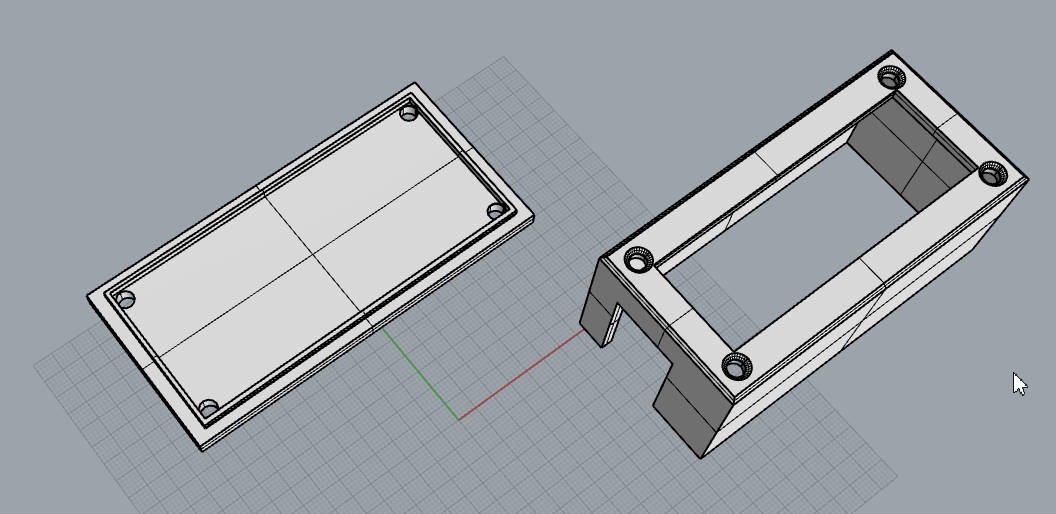
Designed the LCD Casing in Rhino-6
The details about the LCD Screen (16*2 I2C) used in the Final Project could be found in the Week 12/Assignment 13 of Output Devices.
 RFID Case Print Ongoing | 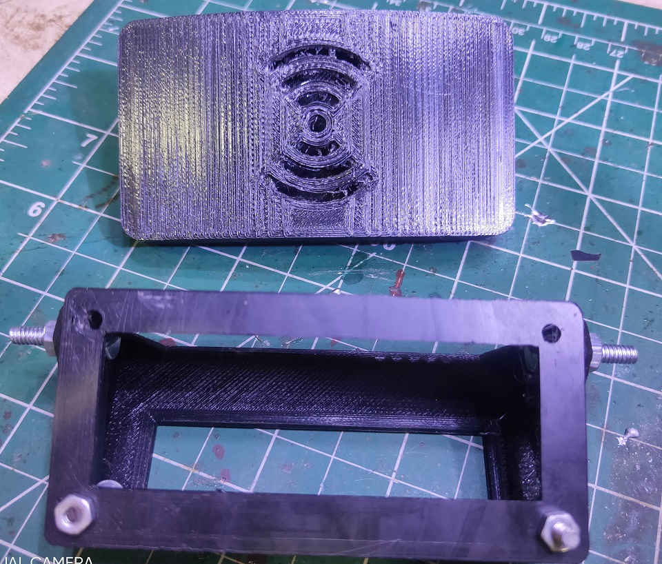 3D Printed LCD Case and RFID Sensor Case |
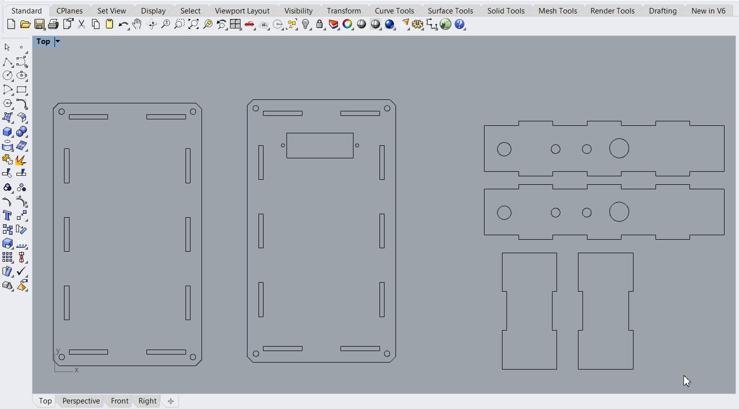
Designed the Final Project Circuit Board Casing in Rhino-6
Laser Cutting:
Details about Laser Cutting could be found in the Week3/Assignment 4 of Computer Controlled Cutting. I have used the Laser Cutter for cutting the PressFit assembly Casing designed for the Final Project Circuit Board. I have Scanned/Itched the Logo of GoatIT over it. I designed it in Rhino-6 (.3DM file); exported from there as ".DXF" file and processed it in RD Works by importing it and then did the Laser utting of the ".RLD" file.
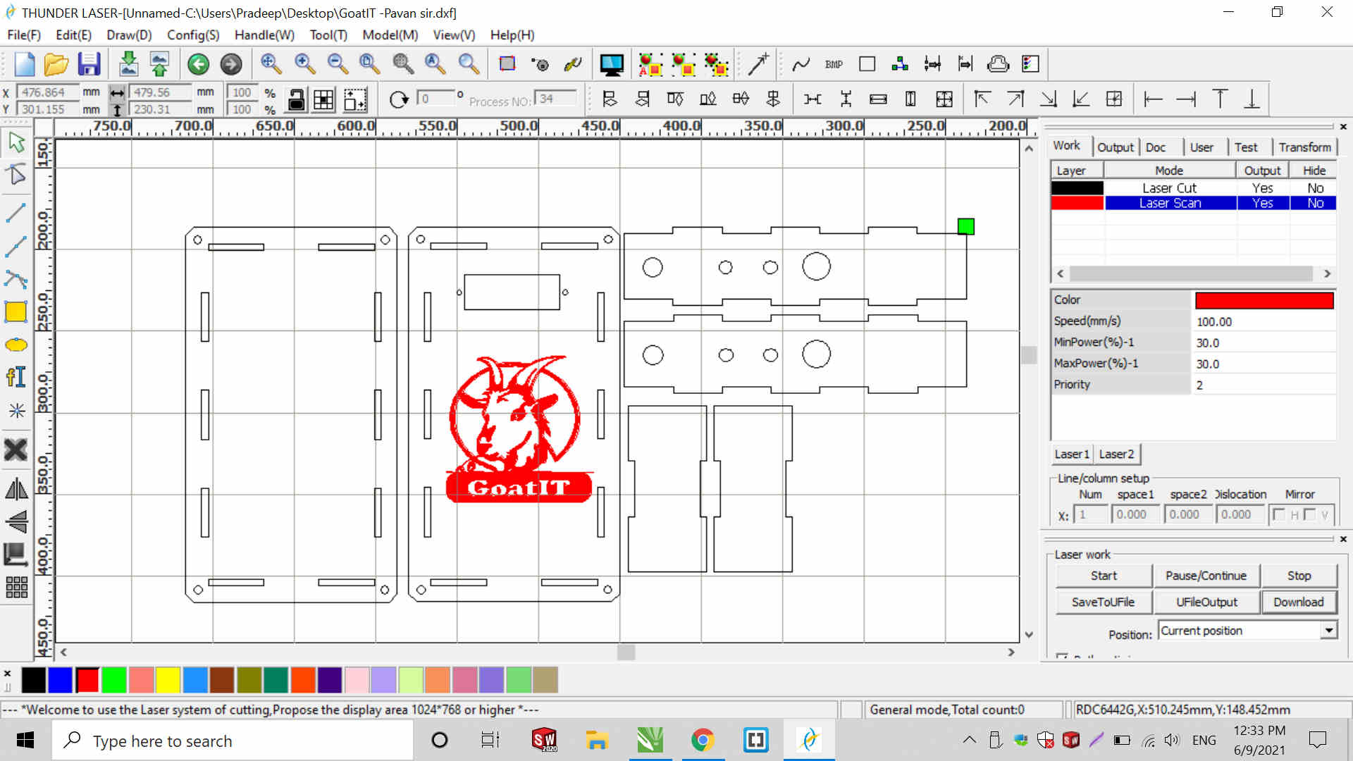
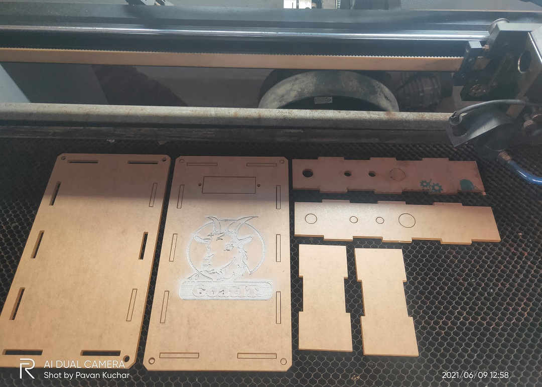
Final Circuit Board Case after Laser Cutting
Circuit Board Casing after removing the Protective Paper cover and Pressfit assembly
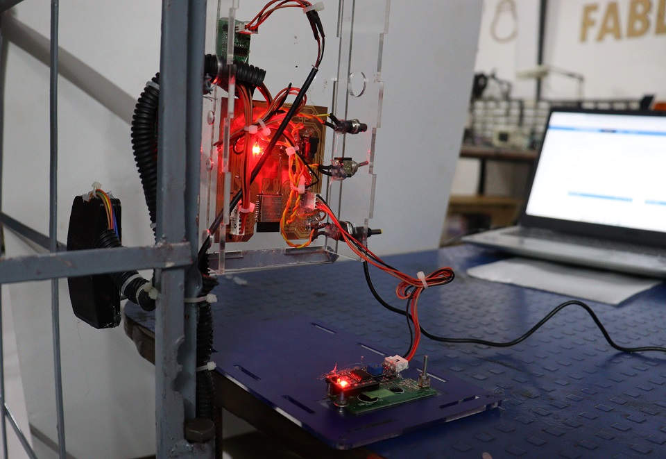
Input and Output Devices attached to Final Project PC Board for Testing
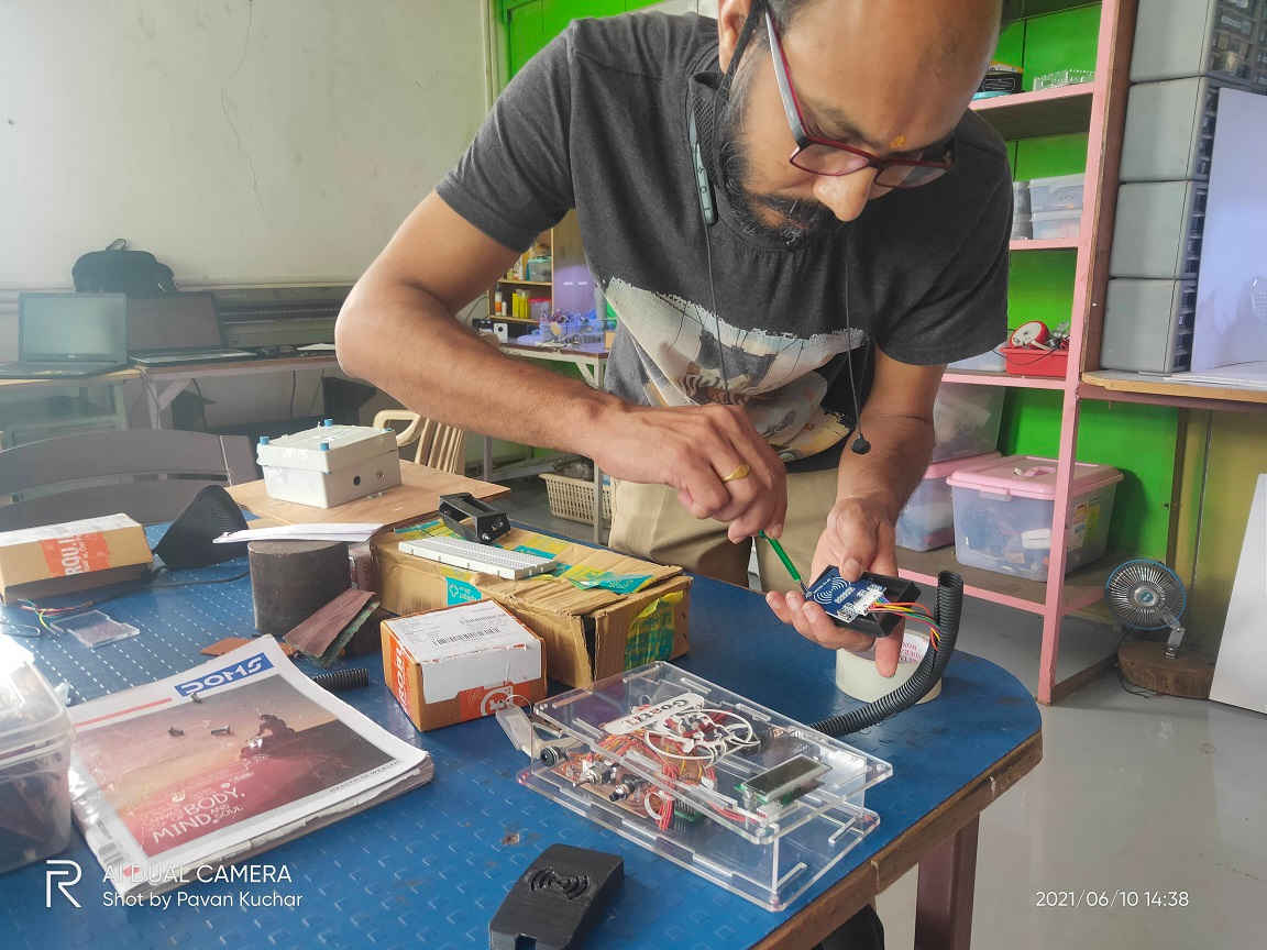
Assembling the Circuit Board in the Casing
 Connections and Wiring organized properly in the Circuit Box | 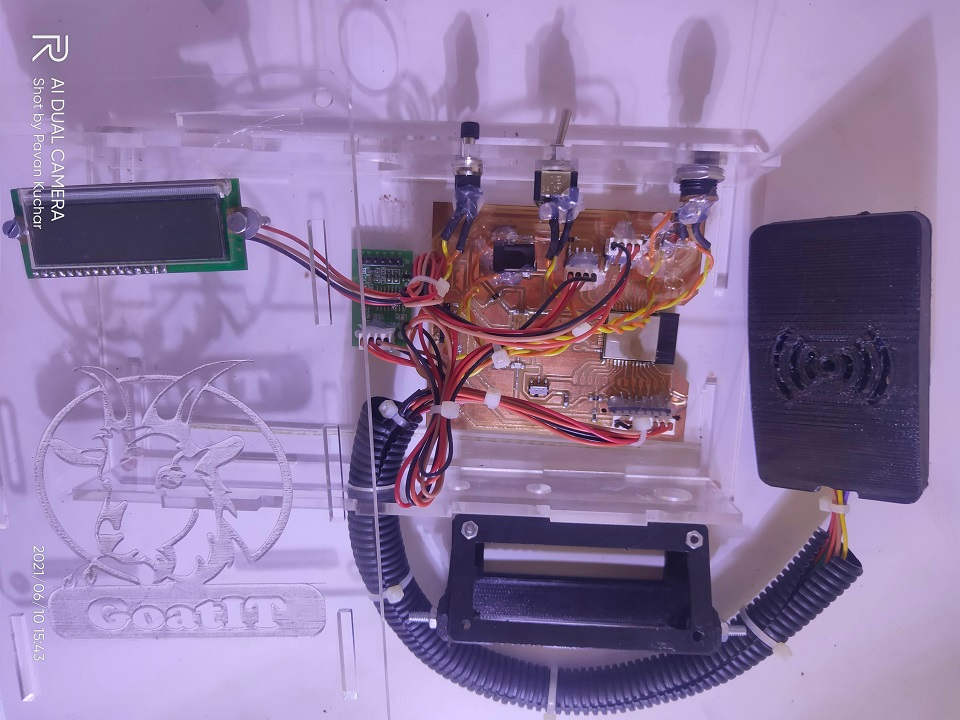 Sensors attached and Boards and Modules fixed in the Circuit Box |
The design of LCD case was according to the LCD that I was using but it was not working later. So, I was given another LCD. I then Soldered the I2C module to it. This LCD was different than the previous one. I soldered the I2C module to it. It didnt had the Backlit. So, I didnt used the LCD case and fitted it directly in the Circuit Board Casing.
I powered up the Circuit Board with 5V 1 Ampere DC Adaptor for testing it. I also attached the ON/OFF switch, Reset Button and provision for Adaptor in the Casing. All the connections were shielded with Heat Shrink, Cable Tie and put under flexible pipe. The internal connections of the wires was twisted and Glue was applied to keep them in place.
I even marked the connectors to easily identify the inner and outer sides. I marked on the PCB and one side of the connector so that the two points could be matched and error in connections could be avoided.
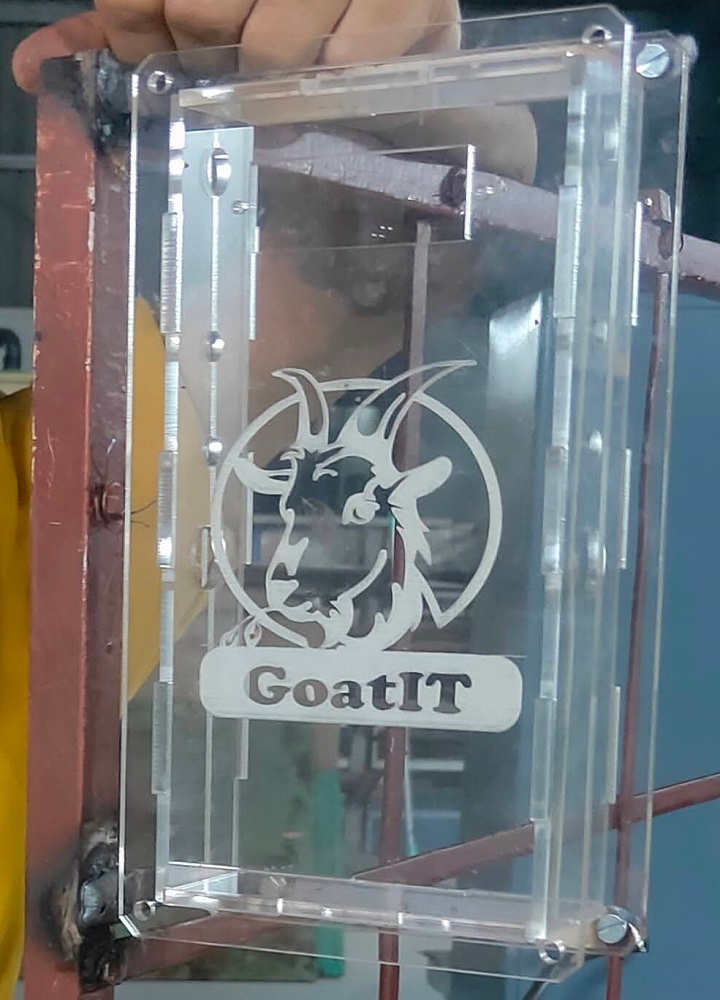
The Logo of GoatIT and the Scanned/Itched Goat on the Case were not visible properly. So, I applied the Blue colored Vinyl Paper on the back side. I used the design of press fit and cut he Vinyl so that slots could be properly matched.
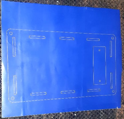 Vinyl Cutting for applying on Circuit Casing | 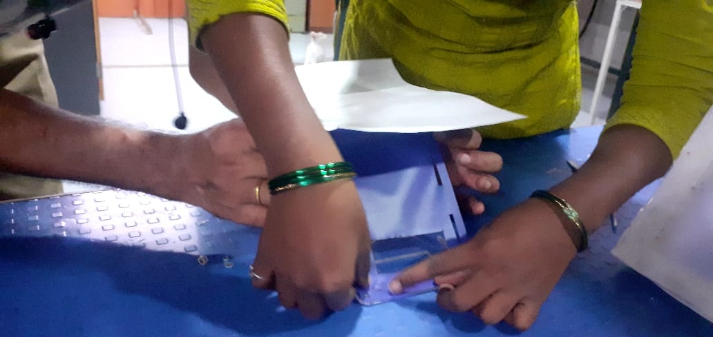 Applying Vinyl on the Circuit Casing |
Costing Estimate of my Final Project:
The Bill of Material (BOM) for the Material and the Components is as given below:
| Material / Component | Quantity | Rate/Price in INR | Approx. Price |
|---|---|---|---|
| Metal: | 75 Feet 3*3 feet 27 feet 10 | Rs. 75/Kg Rs. 65/Kg Rs. 50/Kg Rs. 100/- | Rs. 2000/- Rs. 1200/- Rs. 300/- Rs. 200/- |
| Primer Red Oxide, Oil Paint, Thinner, Brush | 1 Liter | Rs. 200 rs | Rs. 400/- |
| Load Cell 150 Kg | 01 | Rs. 600/- | Rs. 650/- (GST + Delivery Charges) |
| ESP32 Wroom D uC | 01 | Rs. 350/- | Rs. 350/- |
| HX711 Module | 01 | Rs. 75/- | Rs. 75/- |
| RFID Tag Reader and Tags | 01 | Rs. 250/- | Rs. 250/- |
| 16*2 LCD | 01 | Rs. 200/- | Rs. 200/- |
| Miscellaneous Electronic Components | As prescribed | Rs. 200/- | Rs. 200/- |
Total Cost of the Project would be around Rs. 5825/-
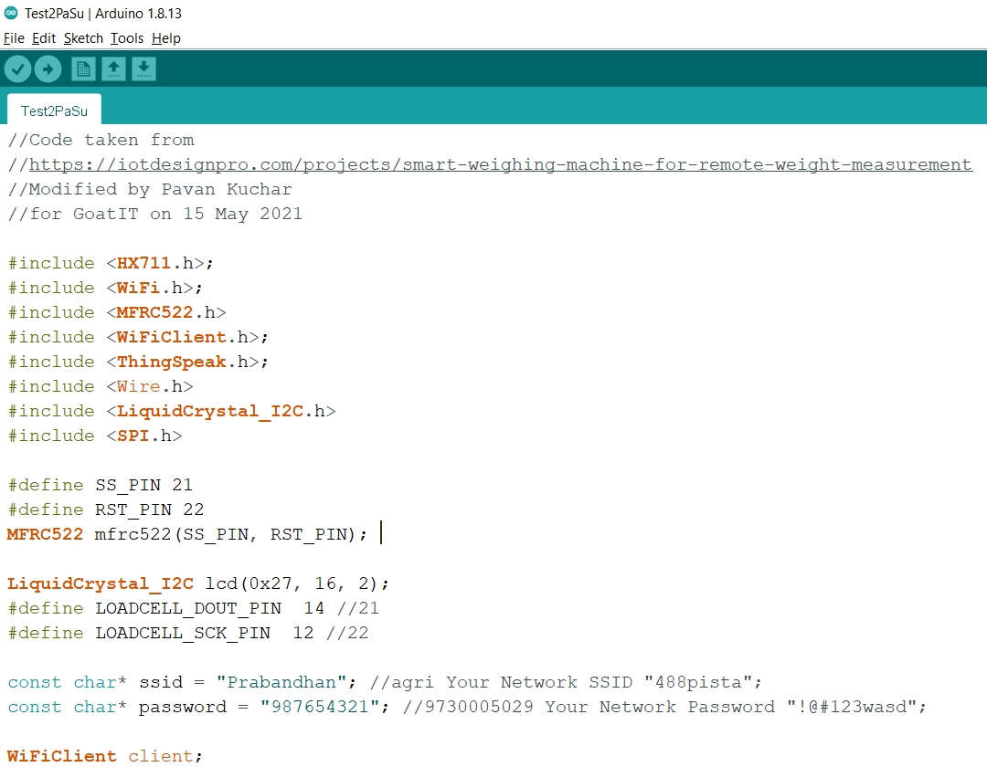
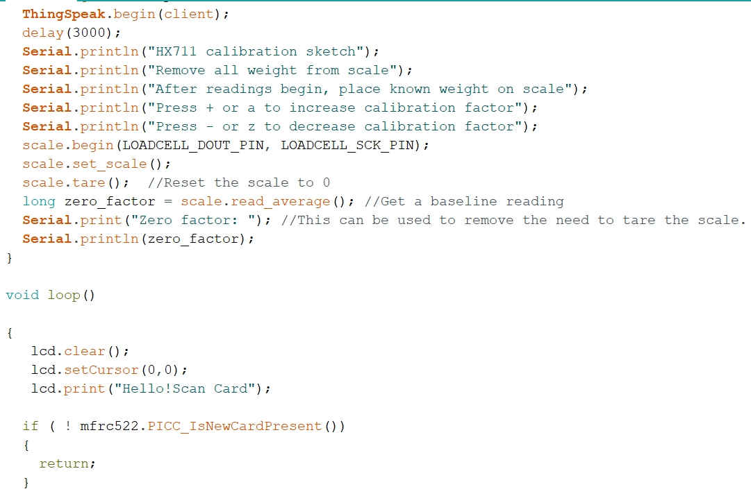
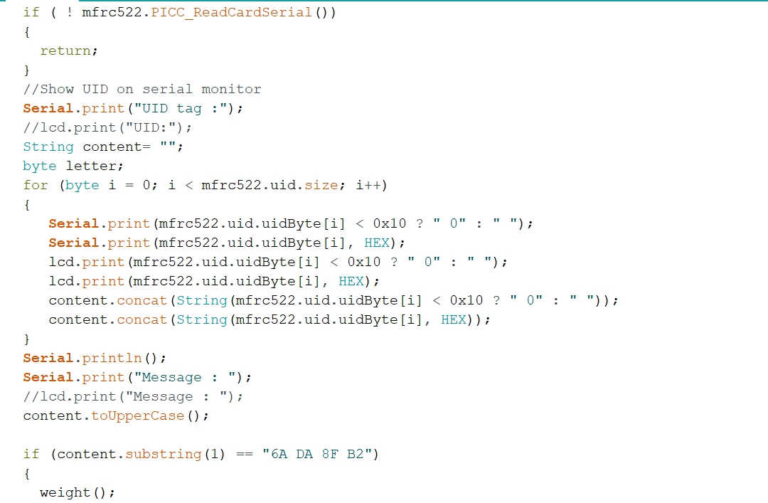
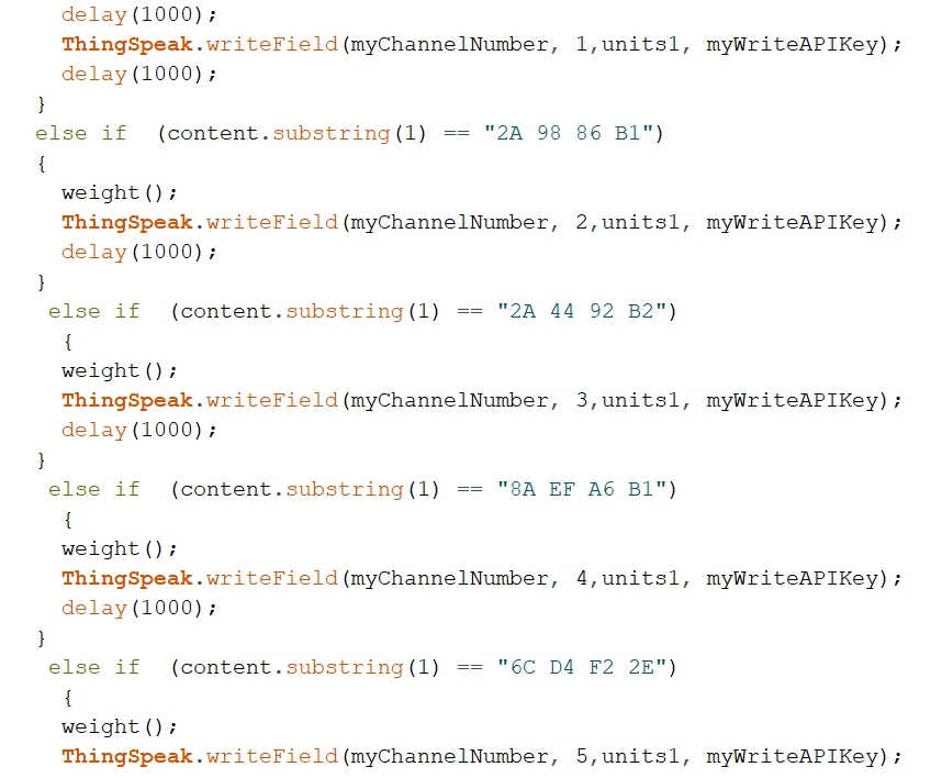
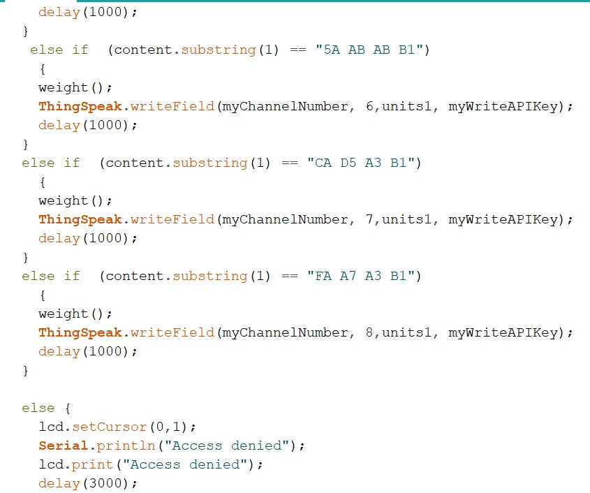
Final Project Sketch/Code:
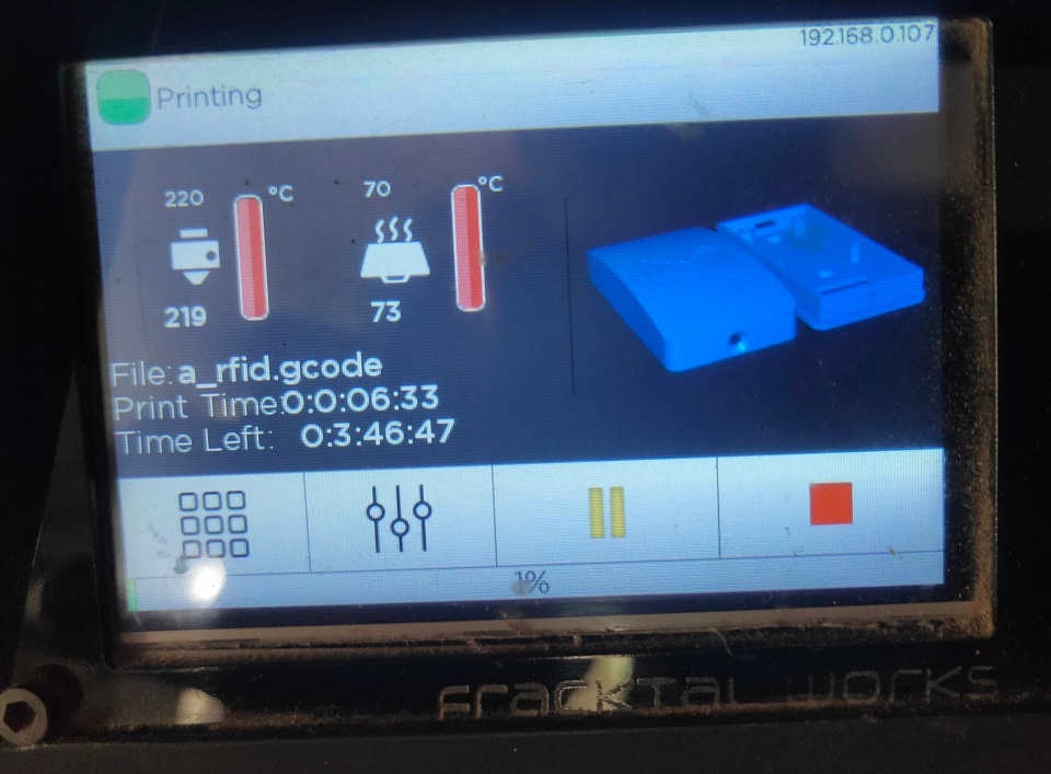
The Code was prepared in stages. I first of all tested the Sensors (Input Devices) and the Output devices with the default pins on ESP32 module suggested by the tutorials and references on the Internet sources like RandomNerdTutorials, hackaday, LastMinuteEngineers etc.
The Addresses of the RFID Tags were noted and incorporated in the Code. The Load Cell was Caliberated and the Caliberation Factor was included in the Final Sketch. A Channel dedicated to the Final Project - GoatIT was formed and edited to receive the readings. Its API write key was included in the Sketch. The SSID Address and Password of the WiFi was included for connecting the ESP32 with the Server/Channel.
The MFRC522, HX711 modules and the LCD was tested in isolation. Then the ThingsSpeak code and WiFi were tested seperately. Then, all these codes were combined to form the Code for Final Project. The Codes are given in the Downloads section.
//Code taken from
//https://iotdesignpro.com/projects/smart-weighing-
machine-for-remote-weight-measurement
//Modified by Pavan Kuchar
//for GoatIT on 15 May 2021
#include <HX711.h>;
#include <WiFi.h>;
#include <MFRC522.h>
#include <WiFiClient.h>;
#include <ThingSpeak.h>;
#include <Wire.h>
#include <LiquidCrystal_I2C.h>
#include <SPI.h>
#define SS_PIN 21
#define RST_PIN 22
MFRC522 mfrc522(SS_PIN, RST_PIN);
LiquidCrystal_I2C lcd(0x27, 16, 2);
#define LOADCELL_DOUT_PIN 14 //21
#define LOADCELL_SCK_PIN 12 //22
const char* ssid = "Prabandhan"; //agri Your Network SSID "488pista";
const char* password = "987654321"; //9730005029 Your Network Password "!@#123wasd";
WiFiClient client;
unsigned long myChannelNumber = 1323804; //Your Channel Number (Without Brackets) 858718;
const char * myWriteAPIKey = "8HJ7ZGI6WNBV5FXQ"; //Your Write API Key "NLDSW5N6UHWHSOHO";
HX711 scale;
float calibration_factor = 15050;
// 29730 this calibration factor is adjusted according to my load cell
float units;
float units1;
float ounces;
void setup()
{
Serial.begin(9600);
SPI.begin();
mfrc522.PCD_Init();
Wire.begin(33, 32); //(D2, D1)
lcd.init(); //lcd.begin()
lcd.backlight();
lcd.print("GoatIT"); //"Circuit Digest"
lcd.setCursor(0,1);
lcd.print("ESP32 Wg Scale"); //NodeMCU Wg Scale
delay(2000);
lcd.clear();
lcd.print("Connecting Wifi");
lcd.setCursor(0,1);
lcd.print("And Thingsspeak");
WiFi.begin(ssid, password);
ThingSpeak.begin(client);
delay(3000);
Serial.println("HX711 calibration sketch");
Serial.println("Remove all weight from scale");
Serial.println("After readings begin, place known weight on scale");
Serial.println("Press + or a to increase calibration factor");
Serial.println("Press - or z to decrease calibration factor");
scale.begin(LOADCELL_DOUT_PIN, LOADCELL_SCK_PIN);
scale.set_scale();
scale.tare(); //Reset the scale to 0
long zero_factor = scale.read_average(); //Get a baseline reading
Serial.print("Zero factor: ");
//This can be used to remove the need to tare the scale. Useful in permanent scale projects.
Serial.println(zero_factor);
}
void loop()
{
lcd.clear();
lcd.setCursor(0,0);
lcd.print("Hello!Scan Card");
if ( ! mfrc522.PICC_IsNewCardPresent())
{
return;
}
if ( ! mfrc522.PICC_ReadCardSerial())
{
return;
}
//Show UID on serial monitor
Serial.print("UID tag :");
//lcd.print("UID:");
String content= "";
byte letter;
for (byte i = 0; i < mfrc522.uid.size; i++)
{
Serial.print(mfrc522.uid.uidByte[i] < 0x10 ? " 0" : " ");
Serial.print(mfrc522.uid.uidByte[i], HEX);
lcd.print(mfrc522.uid.uidByte[i] < 0x10 ? " 0" : " ");
lcd.print(mfrc522.uid.uidByte[i], HEX);
content.concat(String(mfrc522.uid.uidByte[i] < 0x10 ? " 0" : " "));
content.concat(String(mfrc522.uid.uidByte[i], HEX));
}
Serial.println();
Serial.print("Message : ");
//lcd.print("Message : ");
content.toUpperCase();
if (content.substring(1) == "6A DA 8F B2")
{
weight();
delay(1000);
ThingSpeak.writeField(myChannelNumber, 1,units1, myWriteAPIKey);
delay(1000);
}
else if (content.substring(1) == "2A 98 86 B1")
{
weight();
ThingSpeak.writeField(myChannelNumber, 2,units1, myWriteAPIKey);
delay(1000);
}
else if (content.substring(1) == "2A 44 92 B2")
{
weight();
ThingSpeak.writeField(myChannelNumber, 3,units1, myWriteAPIKey);
delay(1000);
}
else if (content.substring(1) == "8A EF A6 B1")
{
weight();
ThingSpeak.writeField(myChannelNumber, 4,units1, myWriteAPIKey);
delay(1000);
}
else if (content.substring(1) == "6C D4 F2 2E")
{
weight();
ThingSpeak.writeField(myChannelNumber, 5,units1, myWriteAPIKey);
delay(1000);
}
else if (content.substring(1) == "5A AB AB B1")
{
weight();
ThingSpeak.writeField(myChannelNumber, 6,units1, myWriteAPIKey);
delay(1000);
}
else if (content.substring(1) == "CA D5 A3 B1")
{
weight();
ThingSpeak.writeField(myChannelNumber, 7,units1, myWriteAPIKey);
delay(1000);
}
else if (content.substring(1) == "FA A7 A3 B1")
{
weight();
ThingSpeak.writeField(myChannelNumber, 8,units1, myWriteAPIKey);
delay(1000);
}
else {
lcd.setCursor(0,1);
Serial.println("Access denied");
lcd.print("Access denied");
delay(3000);
}
}
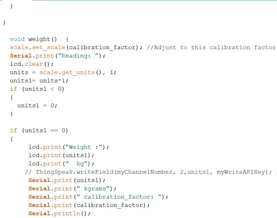
void weight()
{
scale.set_scale(calibration_factor);
//Adjust to this calibration factor
Serial.print("Reading: ");
lcd.clear();
units = scale.get_units(), 1;
units1= units*1;
if (units1 < 0)
{
units1 = 0;
}
if (units1 == 0)
{
lcd.print("Weight :");
lcd.print(units1);
lcd.print(" kg");
// ThingSpeak.writeField(myChannelNumber, 2,units1, myWriteAPIKey);
//Update in ThingSpeak
Serial.print(units1);
Serial.print(" kgrams");
Serial.print(" calibration_factor: ");
Serial.print(calibration_factor);
Serial.println();
delay(1000);
}
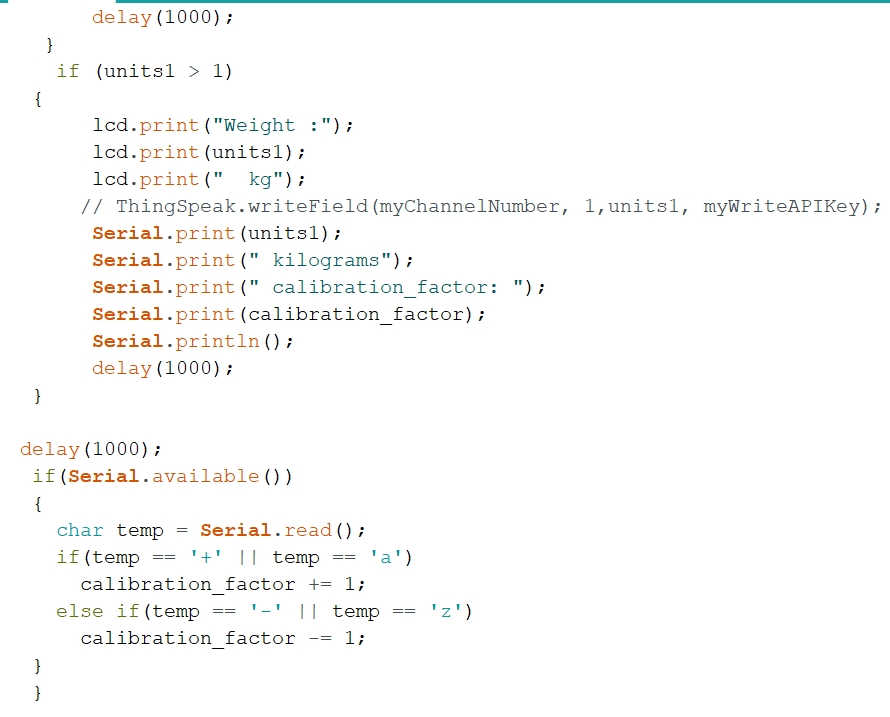
if (units1 > 1)
{
lcd.print("Weight :");
lcd.print(units1);
lcd.print(" kg");
// ThingSpeak.writeField(myChannelNumber, 1,units1, myWriteAPIKey); //Update in ThingSpeak
Serial.print(units1);
Serial.print(" kilograms");
Serial.print(" calibration_factor: ");
Serial.print(calibration_factor);
Serial.println();
delay(1000);
}
delay(1000);
if(Serial.available())
{
char temp = Serial.read();
if(temp == '+' || temp == 'a')
calibration_factor += 1;
else if(temp == '-' || temp == 'z')
calibration_factor -= 1;
}
}
The functioning and Coding of the RFID Tag Reader (MFRC522 module), Load Cell with HX711 module is discussed in detail in the Input Devices Week. and the functioning of the 16*2 LCD screen with I2C is discussed in the Output Devices Week.
Video Stream showing Testing the Code:
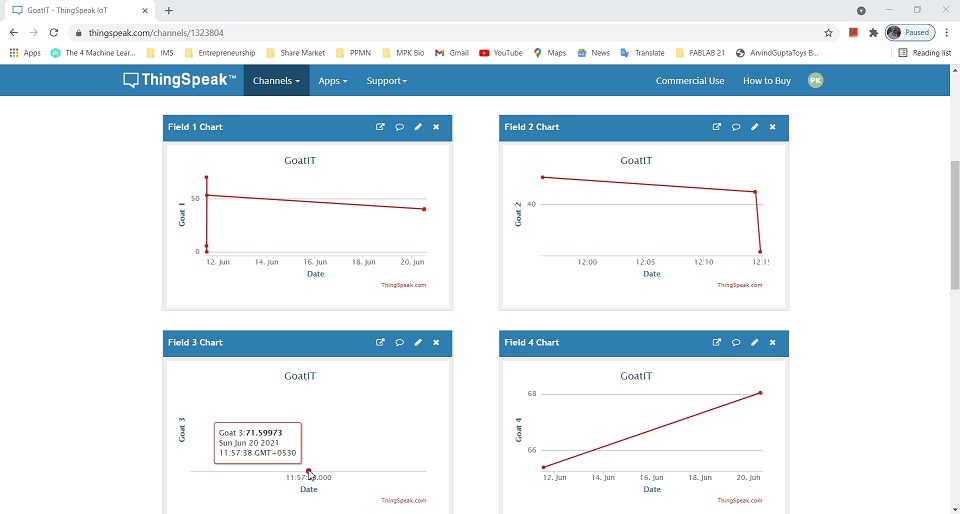
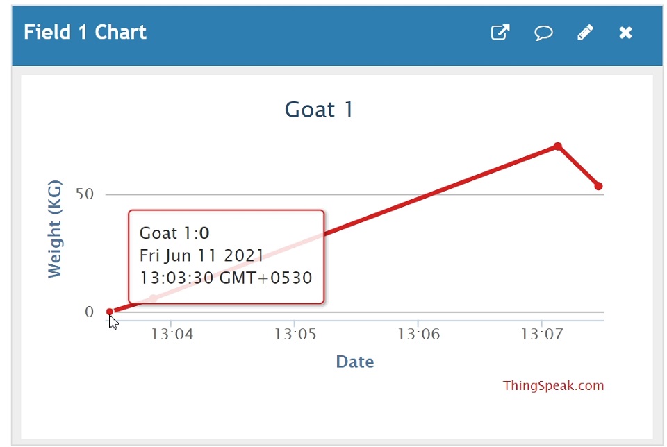
Readings received on the ThingsSpeak Channel-GoatIT:
The Test Results of the Readings received from the Final Project on the Channel are shown below.
 | 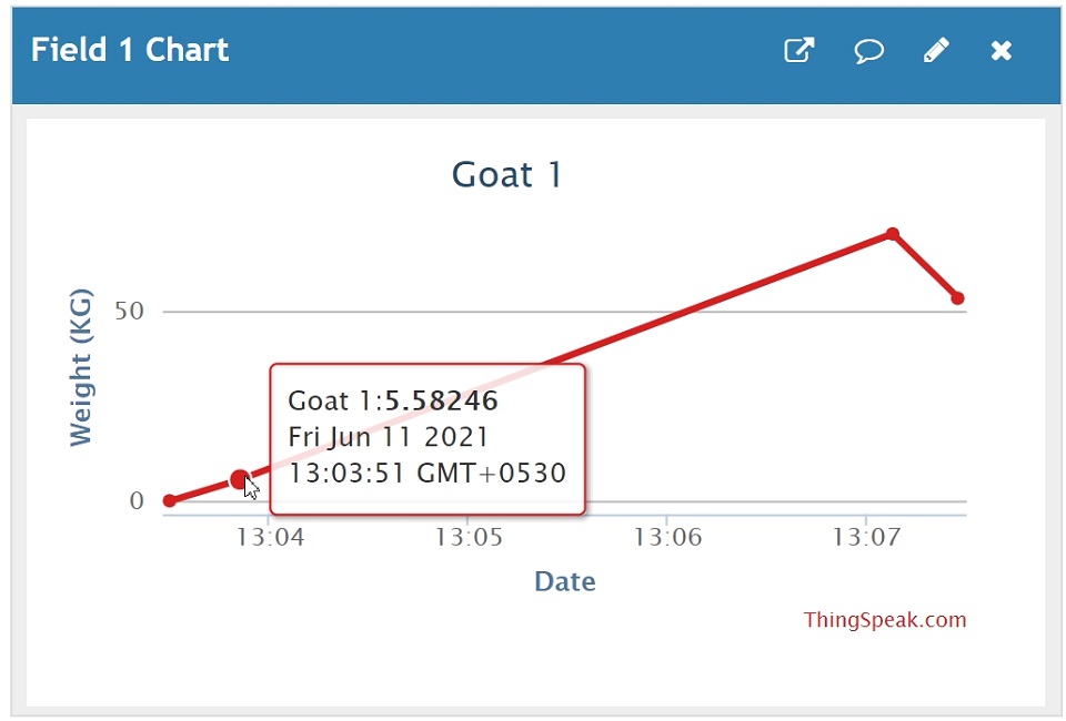 | 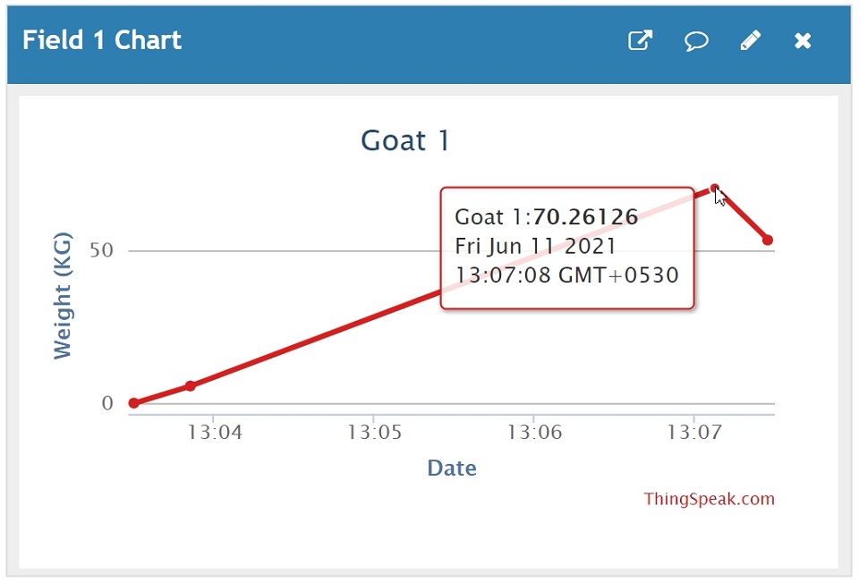 | 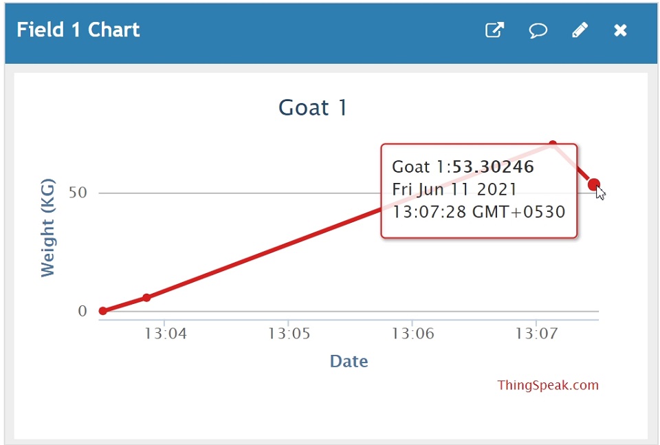 |
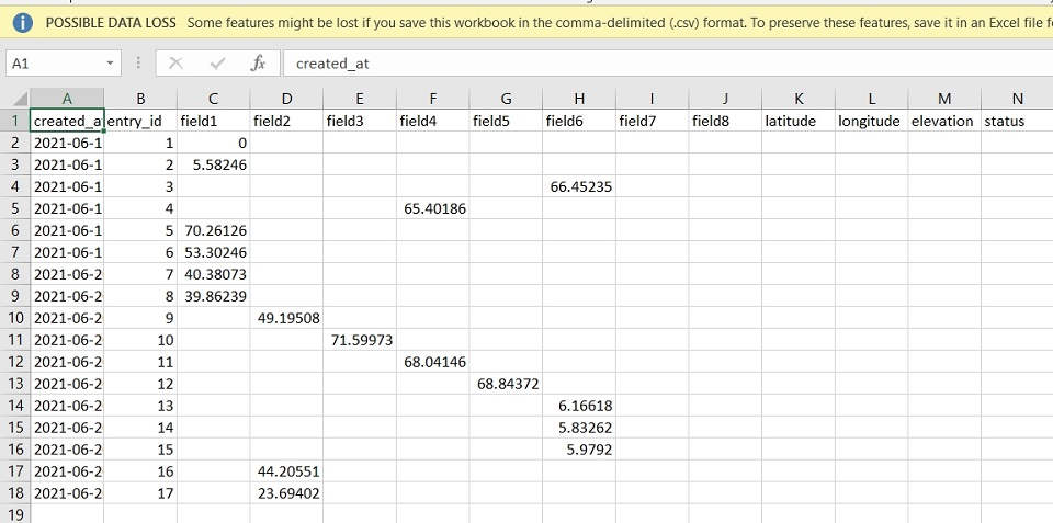
I downloaded the Data by going through Export Data in the Channel and saved the data received in .CSV file format. It appears in the following manner in the Excel Sheet.
Global Final Project Presentation:
My Final Project Presentation was scheduled on 11th June 2021. The Slide(.png) and the Video prepared for the same is -
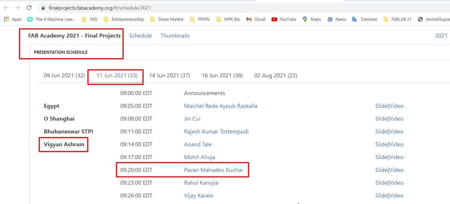
Final Presentation Schedule showing My Turn on 11th June
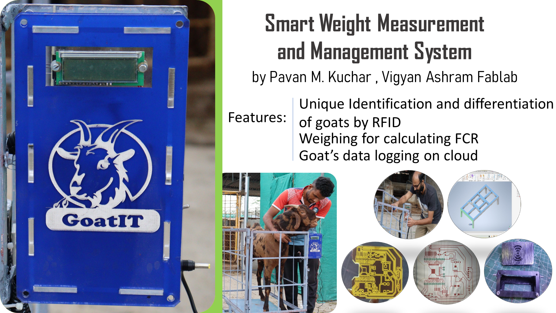
.png file of Presentation
Video for Final Project Presentation
My Presentation started on the 17:07 th Minute. The Link to see the Recording of the Final Presentation is here
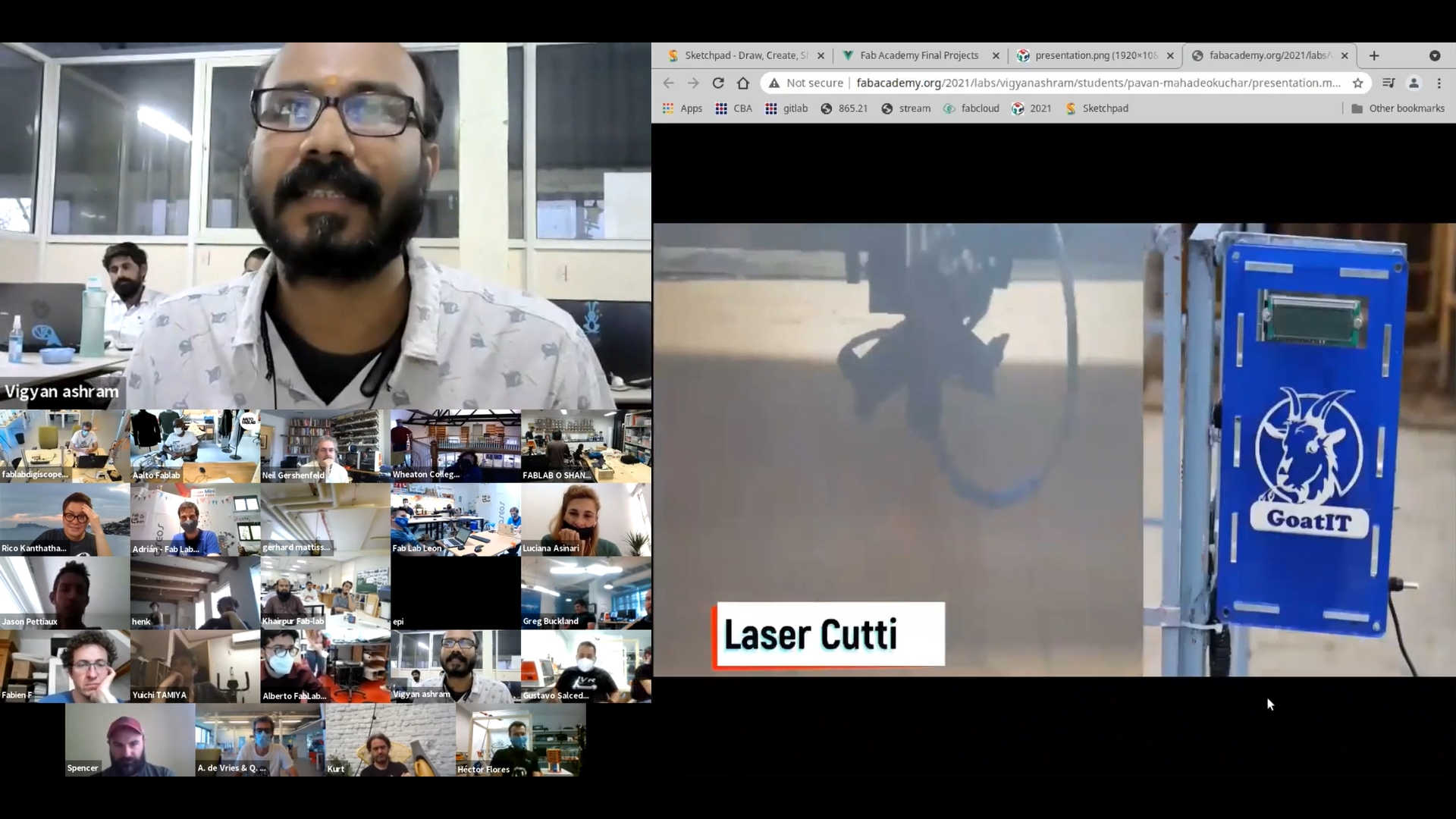
Glimpse from my Final Presentation
Prof. Neil suggested me to show the byte from the Video where Weight is displayed to confirm that the Project works. He also suggested to work on making the Casing Weather proof. I made the casing from Acrylic for aesthetic appeal. But, the circuit could be placed in a PPE box for better protection. After the deployment of this Project to Vigyan Ashram, they assured me of doing it.
I have shot the video showing the readings of weight on the LCD screen.
Video Stream showing the Readings of Weight on the LCD screen.:
But, I realized again that the Video needs to show the readings from the Start. SO, I shot the Video again from Start. I reset the system by pushing the button and then recorded the weight.
Video Stream showing the Readings of Weight on the LCD screen:
Courtesy:
First and Foremost, Thanks to Management of my College, who have futuristic Vision thus permitting and Sponsoring my FabAcademy Course. I am thankful for my Colleagues for taking the Snaps of me while working on the Assignments and Project. I must express my sincere thanks to the Prasad Patil, Sunny Bansode from DIC (Design Innovation Center) who suggested corrections in the design and Fabrication of Weighing Scale. I am thankful to the students Pradeep Kumar (Fab-X), Abhishek (DBRT - Diploma in Basic Rural Technology) for doing most of the Welding. Special Thanks to Bhanudas (Dairy and Animal Husbandary) for helping me with Goats and their Weighing/ putting RFID Tags. Hearty Thanks to the Local Instructors and the FabLab-0, Vigyan Ashram for constant support. Heartfelt thanks to my Family for supporting and motivating me.
Downloads: Original Files
The Original Files contain the Sketch/Codes, 2D and 3D Design Files, PCB Designs, STL files for 3D Printing, .DXF files for Laser Cutting, Datasheets.