

Output Devices:
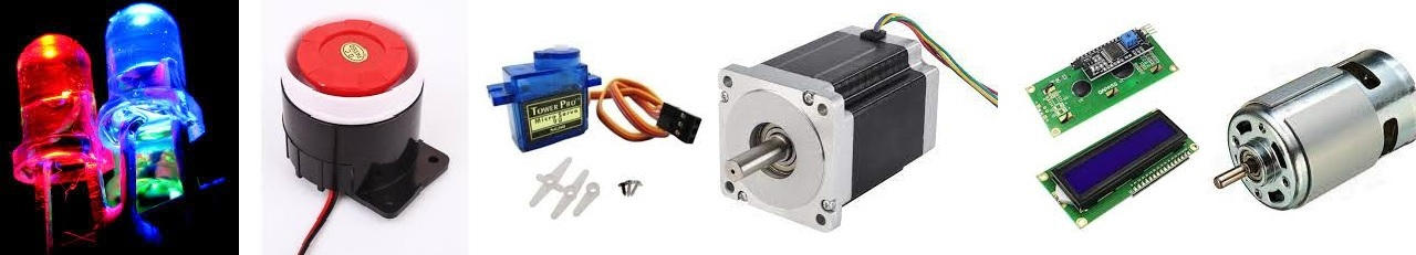
In this Twelfth week of Fab Academy, we had room to explore various Output Devices like the Motors (DC, Stepper, Servo, BLDC, Solenoid), Displays (LCD, OLED, TFT, Arrays), Relays, Speakers, LED (RGB, Arrays), Plotters etc.
Objective:
1. Group assignment:
Details here.This week is having the following Objectives for the Group-
- Measure the power consumption of an output device
- Document your work (in a group or individually)
2. Individual assignment:
Add an output device to a microcontroller board you've designed and program it to do something
Learning Outcomes:
Demonstrate workflows used in controlling an output device(s) with MCU board you have designed
Checklist:
Linked to the group assignment page ✔
Documented how you determined power consumption of an output device with your group ✔
Documented what you learned from interfacing output device(s) to microcontroller and controlling the device(s) ✔
Described your design and fabrication process or linked to previous examples. ✔
Explained the programming process/es you used. ✔
Outlined problems and how you fixed them ✔
Included original design files and code ✔
Included a ‘hero shot/video’ of your board ✔
Opening Quotes:
- "Your daily product determines your output" ― Sunday Adelaja
- "Product is an output of efforts, skills and time"
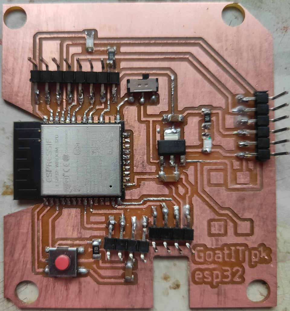
My ESP-32 Board
Output Devices:
- Digital or Dicrete O/P Devices: Turns something On or Off based on Output from Control. Eg. Motor Starter, Contractor
- Analog O/P Devices: Sets an Analog Output Level (Current, Voltage, Resistance...) based on Output from Control. Eg. Valve opening, Heater, Motor Speed
- Data O/P Devices: Provides Data Output (Binary Text etc....) from Control. Input and Output are sometines contained in the single device.
- Operator Interface Devices: Provides the means for the Person to interact with the System, can be Dicrete, Analog or Data. Input and Output are often contained in the single device. eg. Pilot Light, Alphanumeric Display, Touch Pad, Computer.
Light Emitting Diode: Unlike filament lamps, where electrical energy must be converted into heat before light can be produced, Light Emitting Diodes (LEDs) are able to transform electrical energy directly into light energy. Since the LED is a diode, it will only light up when current is in the correct (conducting) direction. Series circuit with a battery, an LED and a lamp.
I have already used the LED in the PCB; RGB, Monochrome LED etc are available.
Motor: Motors can provide movement. They could be used in various Consumer Durables, Controlling Robot Arms(Industry) etc. The Motors that are used mostly in Electronics are Servo, Stepper, BLDC etc.
Buzzer: Buzzers can provide noise. They are used to signal and warn for various things.
Speakers: These are used to amplify the sound.
| Quantity being Measured | Input Device (Sensor) | Output Device (Actuator) |
|---|---|---|
| Light Level | Light Dependant Resistor (LDR) Photodiode Photo-transistor Solar Cell | Lights and Lamps LED’s and Displays Fibre Optics |
| Temperature | Thermocouple Thermistor Thermostat Resistive Temperature Detectors | Heater Fan |
| Force/Pressure | Strain Gauge Pressure Switch Load Cell | Lift and Jack Electromagnet Vibration |
| Position | Potentiometer Encoders Reflective/Slotted Opto-switch LVDT | Motor Solenoid Panel Meters |
| Speed | Tacho-generator Reflective/Slotted Opto-coupler Doppler Effect Sensors | AC and DC Motors Stepper Motor Brake |
| Sound | Carbon Microphone Piezo-electric Crystal | Bell Buzzer LoudSpeaker |
Working of Output Devices:
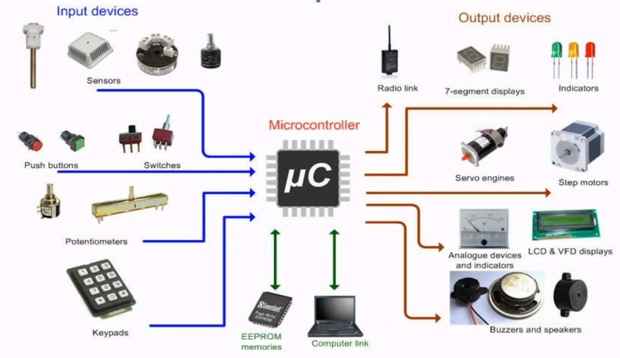
Input Devices/ Sensors convert the inductance, resistance, capacitance into signal and send it to the Microcontroller. uC then reads this impulse; process it and sends the information to the actuator / output device to carry out the desired function as coded / programmed. Output Devices recieve signal from the MicroControllers and carry out the instructions accordingly.
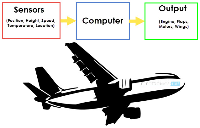
Working of Input - Output Devices
1. Group assignment: Details here.
For this week, we had to measure the Power Consumption of the Output Devices and document our work.
I decided to test the LCD display for the same as I am going to use it in my Final Measurement to display the Weight of the Goats on the Screen.
For calculating the Power consumption, we need to understand about Voltage and Current because Power is equal to Voltage into Current.
Power: It is the amount of energy transferred or converted per unit time. In the International System of Units, the unit of power is the watt, equal to one joule per second. In older works, power is sometimes called activity. Power is a scalar quantity.
The instantaneous electrical power P delivered to a component is given by P(t)=V(t)xI(t) Where
- P(t)= is the instantaneous power, measured in watts (joules per second)
- V(t)= is the potential difference (or voltage drop) across the component, measured in volts
- I(t)= is the current through it, measured in amperes
Voltage: Voltage, electric potential difference, electric pressure or electric tension is the difference in electric potential between two points. The difference in electric potential between two points (i.e., voltage) in a static electric field is defined as the work needed per unit of charge to move a test charge between the two points. In the International System of Units, the derived unit for voltage is named volt.
In SI units, work per unit charge is expressed as joules per coulomb, where 1 volt = 1 joule (of work) per 1 coulomb (of charge). The official SI definition for volt uses power and current, where 1 volt = 1 watt (of power) per 1 ampere (of current).
Current: An electric current is the rate of flow of electric charge past a point or region. An electric current is said to exist when there is a net flow of electric charge through a region.In electric circuits this charge is often carried by electrons moving through a wire. It can also be carried by ions in an electrolyte, or by both ions and electrons such as in an ionized gas (plasma).
The SI unit of electric current is the ampere, which is the flow of electric charge across a surface at the rate of one coulomb per second. The ampere (symbol: A) is an SI base unit. Electric current is measured using a device called an ammeter
Power Consumption Calculations for 16*2 LCD Display:
On ATMega-328P Board:
I have tested the Power Consumption for 16*2 LCD on ATMEGA 328P where 5V supply was given to the Board. I connected the Multimeter in Series with the Vcc. I connected the GND of LCD to GND of the ATMEGA-328P board. I connected the Vcc of the Board to one of the Terminals of the Multimeter and the other Pin of Multimeter to the Vcc of the LCD. This how the Multimeter was connected in Series with the LCD and ATMega Board. I connected the Black Pin of the Multimeter to the Common and Red Pin to the 100mA. I also rotated the knob on the mA/Hz to check the Current.
The reading on the Multimeter was 20.85 mA. I have given a Voltage of 5V. So, the Power consumption will be P= 5 x 20.85 x 10^-3 = 0.1 Watt
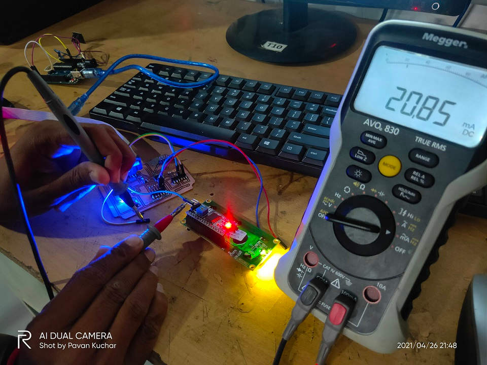
Current (mA) Readings of LCD at 5 Volt Supply
On my ESP-32 Board:
I made the connections in Series like done for ATMEGA earlier. Only thing is I have provided the 3.3 Volts supply.
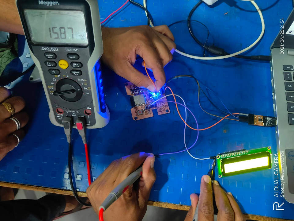
Current (mA) Readings of LCD at 3.3 Volt Supply
The reading on the Multimeter was 15.87 mA. I have given a Voltage of 3.3V. So, the Power consumption will be P= 3.3 x 15.87 x 10^-3 = 0.052371 Watt
I thought that the Power Consumption of LCD would remain the same. But, it has different Current readings for 3.3V and 5V supply and thus the Power Consumption differs. This might be because of the Contrast of the BackLight of the LCD as it changes on different voltage.
2. Individual assignment:
 |
 |
|---|
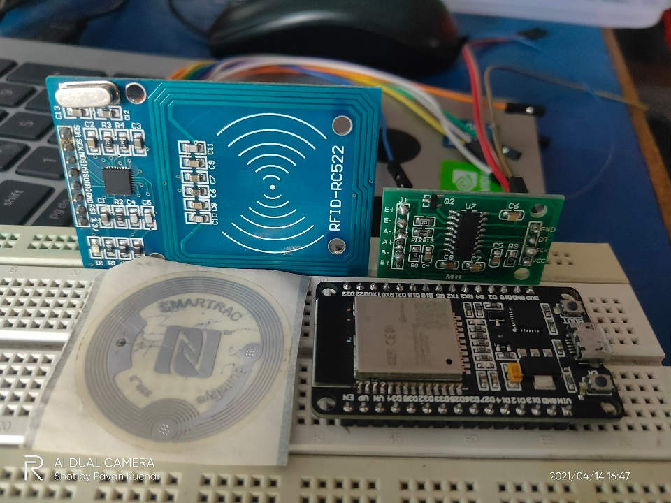
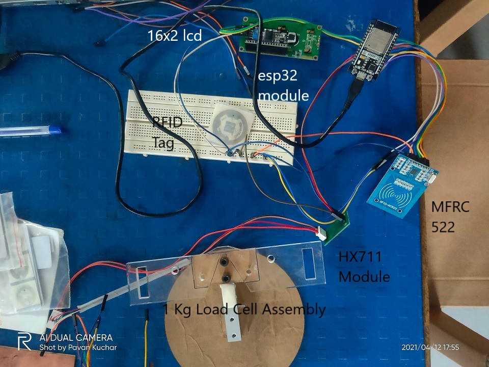
ESP32D + MFRC 522 + HX 711 Module and LCD display connected for Testing:
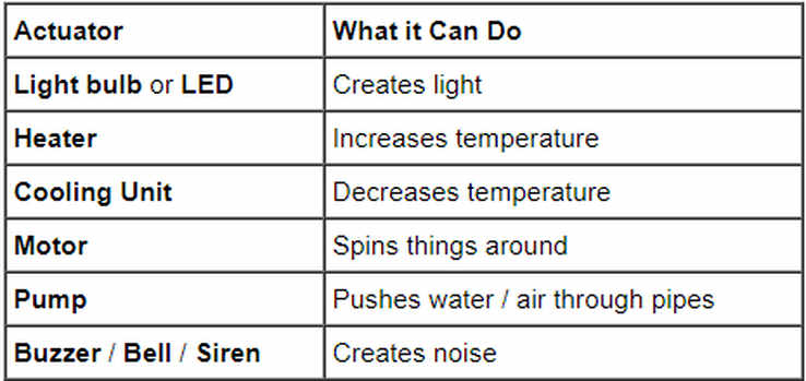
Output Devices:An output device is any piece of hardware item which utilizes whatever data and commands from your micro controller/processor in order to perform a task. This leads to the results of data processing carried out by an information processing system (such as a microcontroller) which converts the electronically generated information into human-undestandable form.
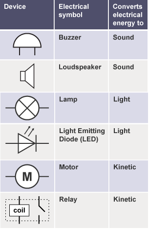
Output devices in electronic systems transform electrical energy into another type of energy, such as light, sound or kinetic energy . Common output devices and their associated energy changes are shown in the table below.
For this Assignment, I decided to test and explore the 16*2 LCD Display that I may use in the Final Project. I would test and compute the Power consumption and interface it with the ESP-32 Board.
I am pursuing Project on Smart Goat Weight Measurement and Monitoring System. For this, I already explained the Sensors like RFID Tag Reader (MFRC-522) and Load Cell with HX711 in the Input Devices Assignment.RFID Tags on the Goats for their Identification. This would also help in maintaining their records of Weight.
I would build a Weighing Machine for thr Goats. Proximity Sensors would be used for automatic door operations.
Load Cell would be used for the Weighing Balance. The weight thus taken would be then displayed and sent to the Cloud for datalog and analysis of the FCR (Food Conversion Ratio) which will help in finding the Profitability and maintaing health and weight record of the Goats.
LCD display would be used for displaying the Weight.
I will use ESP32 Wroom 32D Microcontroller Board for the Project.
The flow of this Assignment is as follows:
- Introduction to LCD Display
- Introduction to Espressif ESP32 Wroom 32D
- Probing the Output Devices:to measure, observe or monitor signals with test probes
- LCD Display
- RGB LED
- Summary:
- Videos and Downloads
Displays:
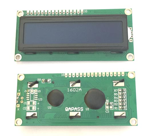
An liquid-crystal display (LCD) is an electronic display module which uses liquid crystal to produce a visible image. The 16×2 LCD display is a very basic module commonly used in DIYs and circuits.
- Features of 16×2 LCD module:
- Operating Voltage is 4.7V to 5.3V
- Current consumption is 1mA without backlight
- Alphanumeric LCD display module, meaning can display alphabets and numbers
- Consists of two rows and each row can print 16 characters.
- Each character is build by a 5×8 pixel box
- Can work on both 8-bit and 4-bit mode
- It can also display any custom generated characters
- Available in Green and Blue Backlight
16x2 Display Equivalents: Dot Matrix LED Display, 7-Segment LED Display, OLED Display, TFT LCD Screen Display
Interface IC like HD44780 is used, which is mounted on the backside of the LCD Module itself to instruct about the Position of the Pixels.
Working Principle:The basic principle in LCD is by the passing of light from one layer (sheet) to another layer with the use of modules. The modules vibrate and align their position at 90 degrees, which allows the polarized sheet to pass the light through it. The molecules are responsible for showing the data on each pixel. Each pixel uses the light-absorbing method to show the digit. To show the value, molecules need to change their position to change the angle of light. So this deflection of light will make the human eye see the light of the remaining part which will make the dark part as a value and digits on the grid pixels. The data, we can see, will be the part where the light gets absorbed. The data will pass towards the molecules and will be there until they are changed.
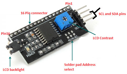
I2C or IIC Protocol:
I2C (I-square-C i.e I2C) means inter-integrated communication protocol. This is usually used to communicate between one master and multiple slaves. One of the best things about using I2C is we can reduce the connections (wiring). If you use normal LCD display, you need a total number of connections are 12. If you use I2C LCD display, you need only just 4 connection. I2C protocol is also known as 2 line protocol.
ESP-32 MicroController:
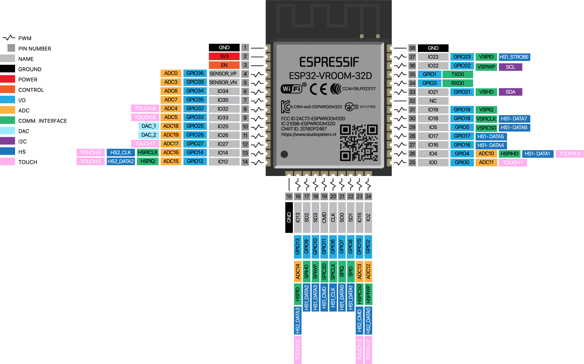
ESP 32 Microcontroller and Pin Out
Design Files of My I/O Board that I will be using for my Final Project:
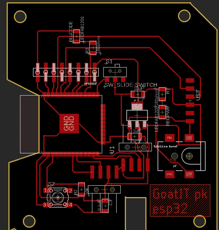
PCB Design
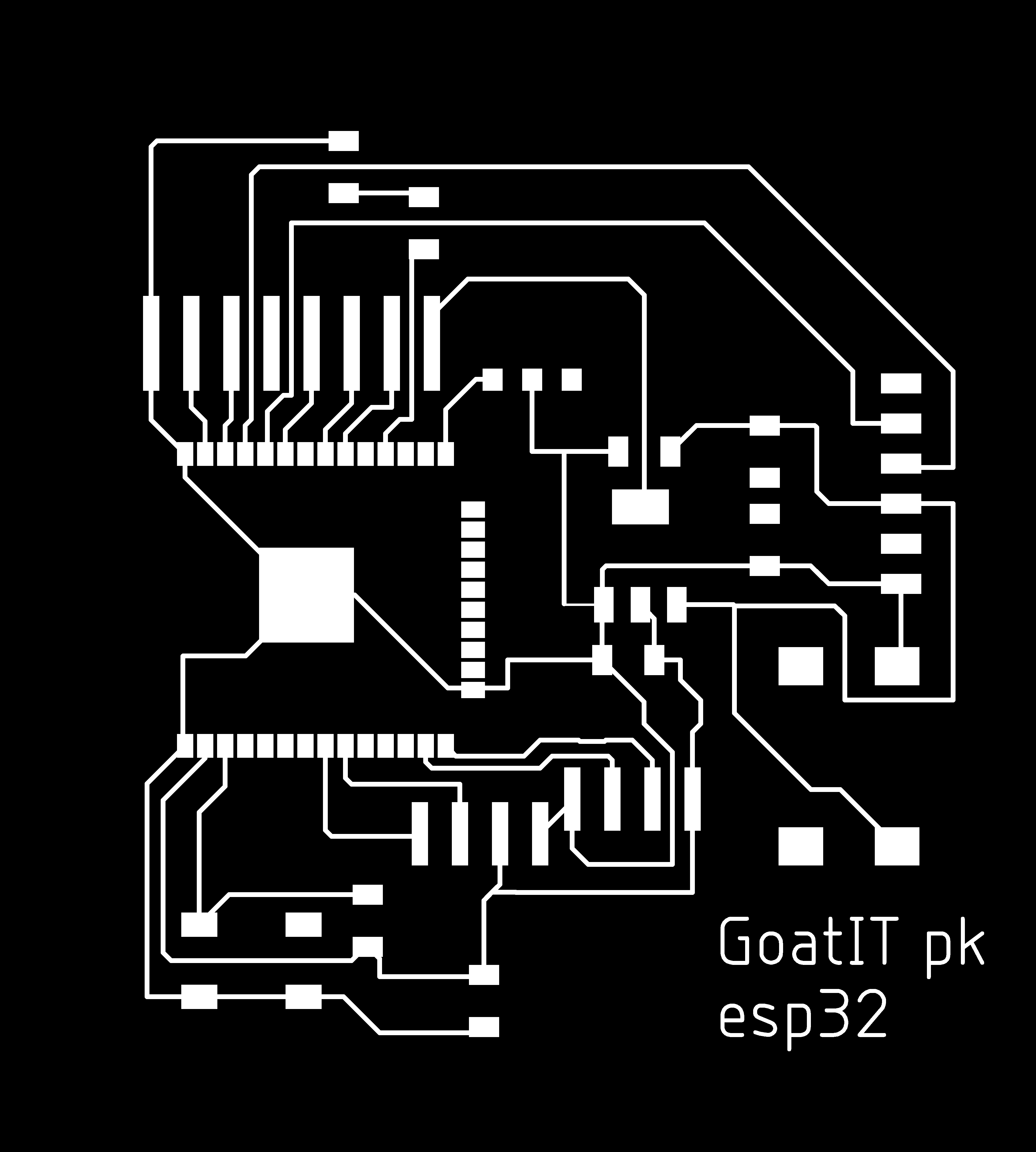 PCB Traces |
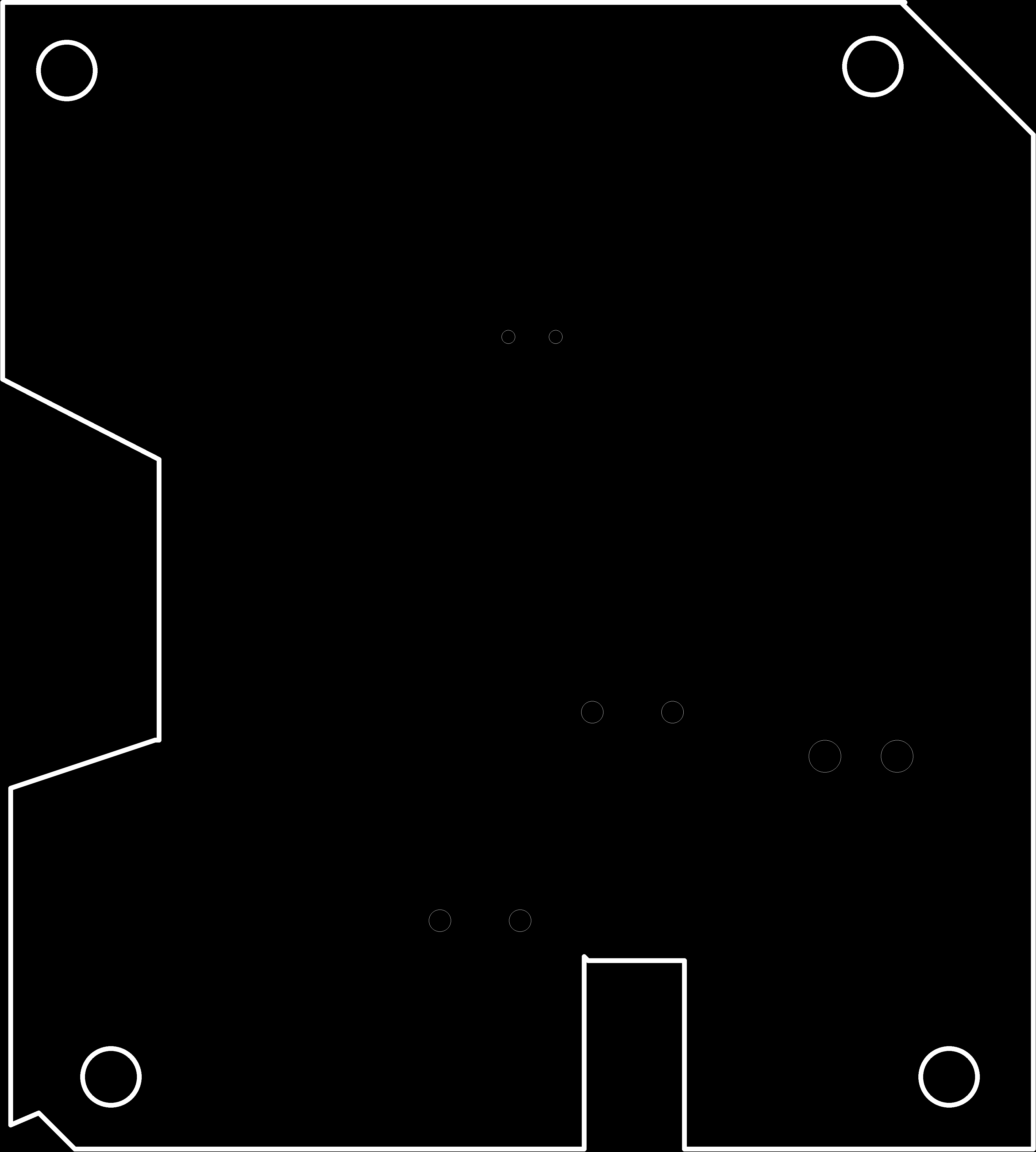 PCB Out |
|---|
After Soldering the components on the ESP-32 PCB, I first ran the echo Code by Dr. Neil on the Board.
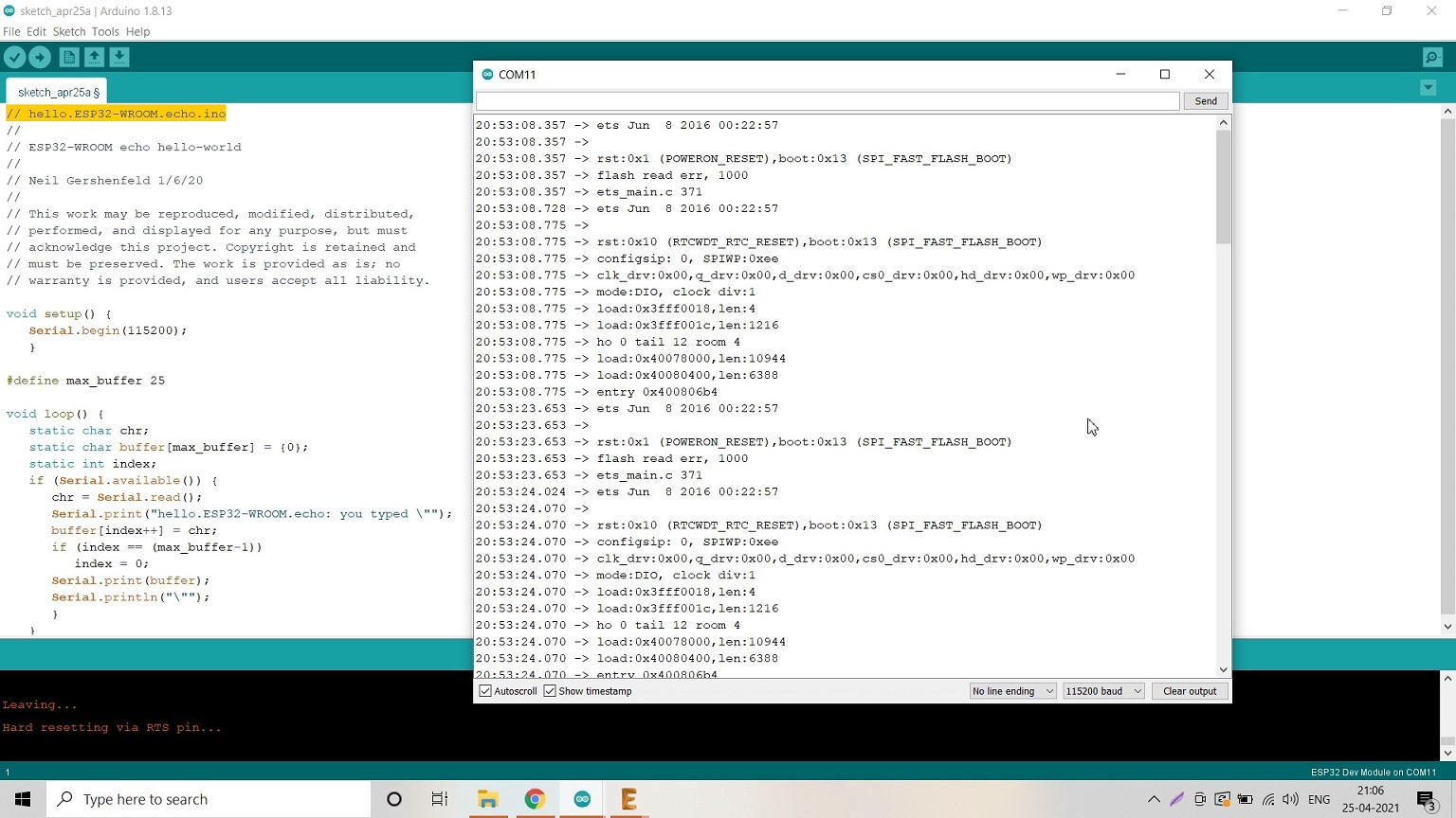
I couldnt understand much about the data displayed in Serial Monitor
Video Stream - LED Blink:
16*2 LCD as Output Device Testing:
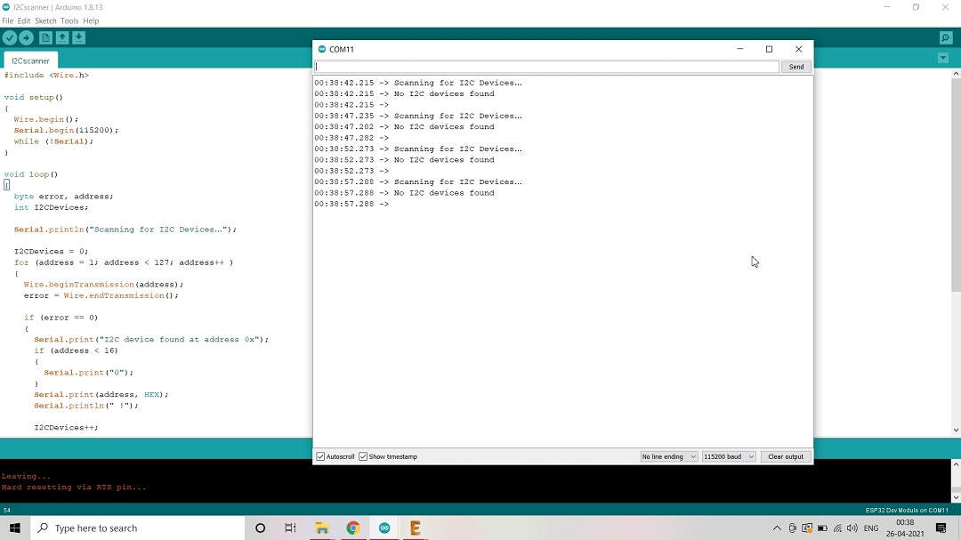
Connected LCD and ran I2C Scanner code to detect Display Address but No I2C device was detected
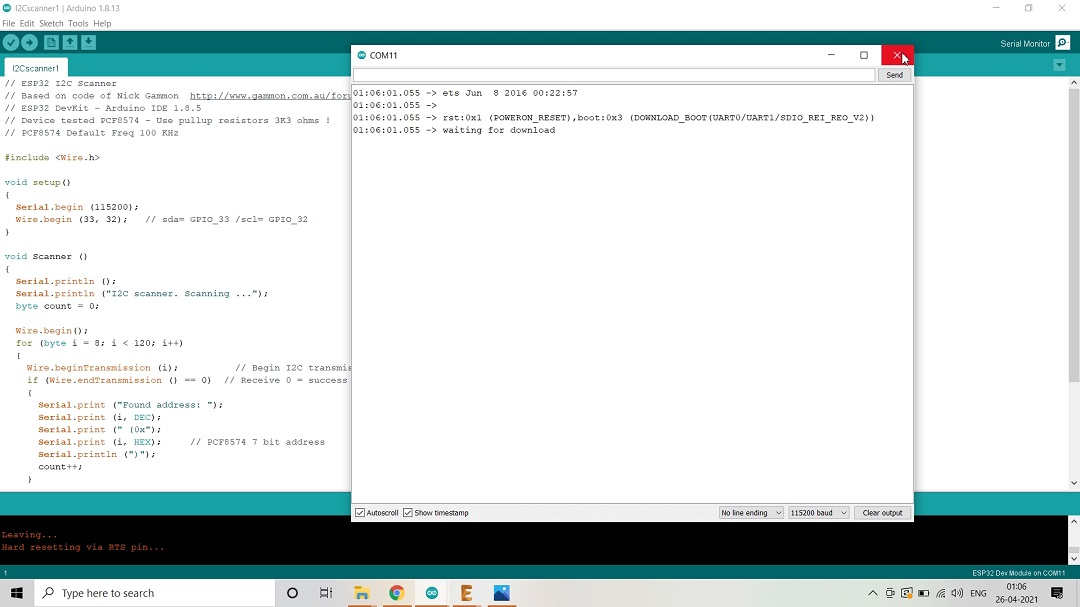
Tried other Code/Program/Sketch; This time defined the IO Pin numbers as well but Alas!
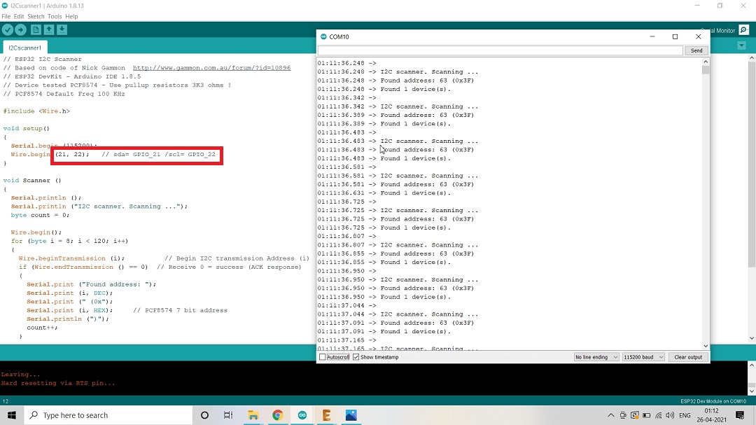
Tried the same Sketch/Code with the Default pins mentioned in the Code and Voila! it worked.
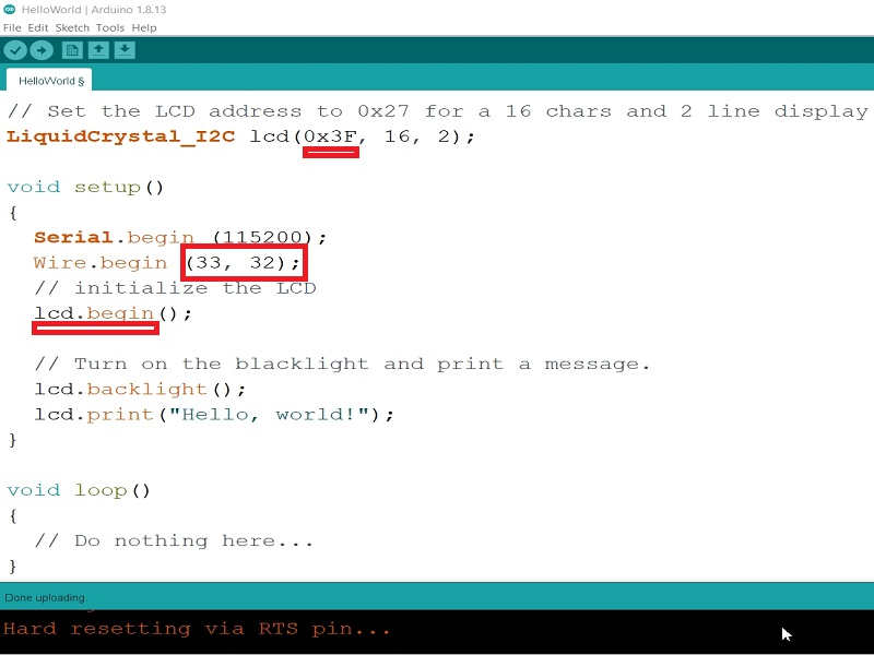
Took the Hello World Example from the Library and defined Pins and I2C Display Address
Tried the Scroll Text Example but it didnt worked. Compared the Sketch that worked and found that "lcd.init" was not mentioned in the library. May be the libraries in the programs are different.
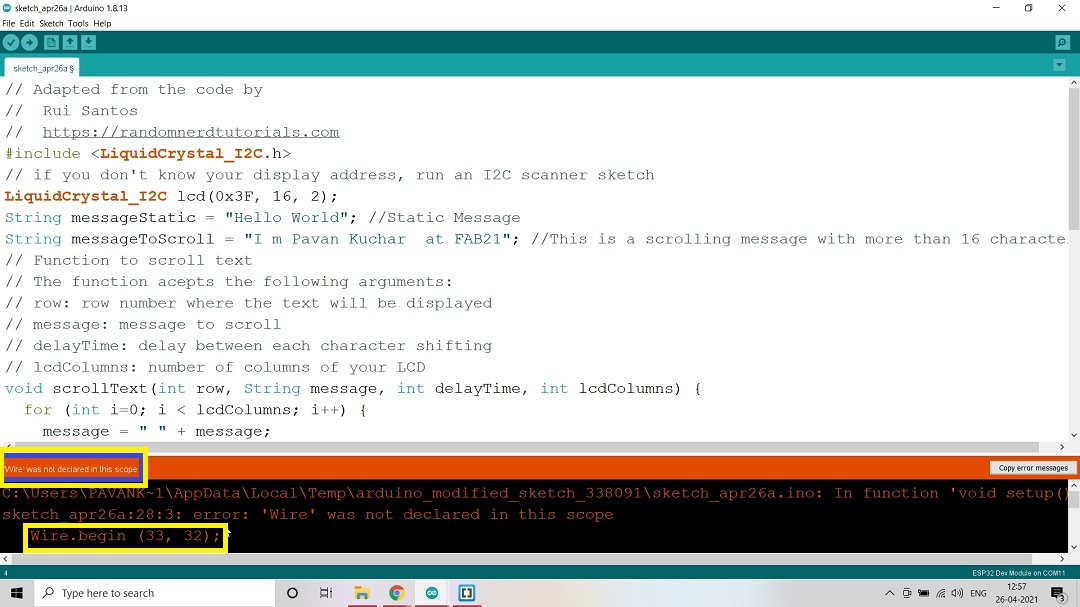
Even "wire.begin" was not declared in the command of Library.
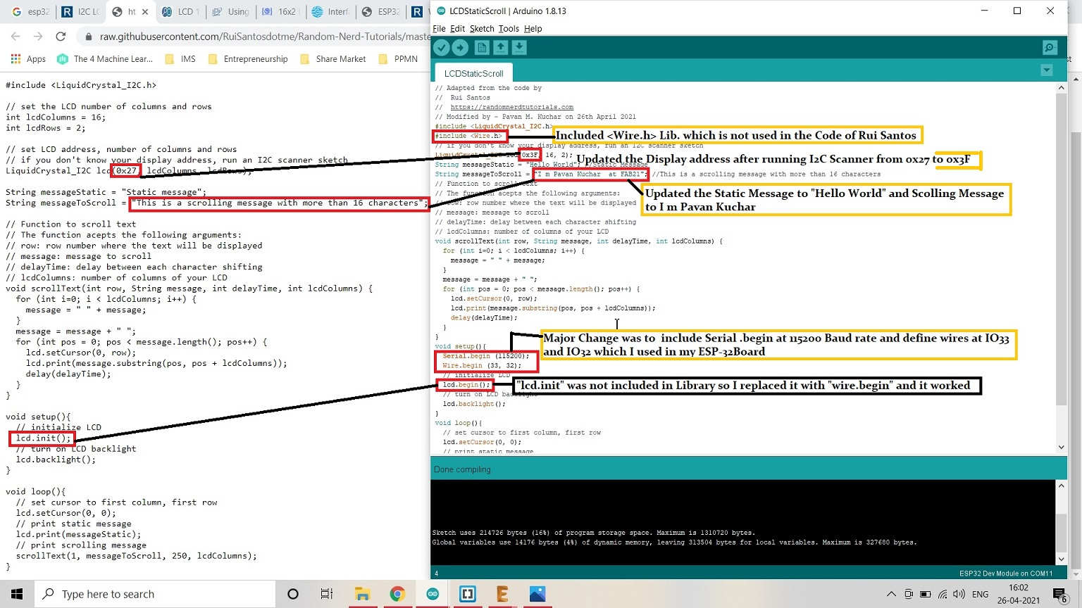
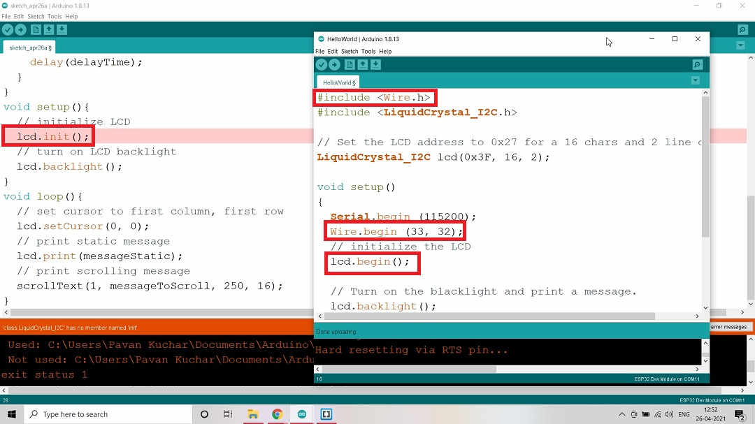
Took the Code from Rui Santos on Random Nerd Tutorials and changed few entries.
I first included "wire.h" library in the code which was not used by Rui Santos. Then I updated the I2C Display Address from 0x27 to "0x3F". I also changed the Static Message to "Hello World" and Scrolling Message to "I m Pavan Kuchar at FAB21".
Major change that I made in the code of Rui Santos was to include "Serial.begin(115200)"; "wire.begin(33,32)". Also, the command "lcd.init()" was not regognized by the program. So I changed it to "lcd.begin()". Atlast, this program was successfully compiled and ran OK.
Even after the Code compiling and verification succesful, I was not able to see anything on the LCD screen. Then I adjusted the contrast of the LCD screen by turning the screw on the back of LCD in Potentiometer (Contrast Adjuster) component attached to the I2C protocol device.
Test Code:
// Adapted from the code by
// Rui Santos
// https://randomnerdtutorials.com
// Modified by - Pavan M. Kuchar on 26th April 2021
#include LiquidCrystal_I2C.h>
#include Wire.h>
// if you don't know your display address, run an I2C scanner sketch
LiquidCrystal_I2C lcd(0x3F, 16, 2);
String messageStatic = "Hello World"; //Static Message
String messageToScroll = "I m Pavan Kuchar at FAB21"; //This is a scrolling message with more than 16 characters
// Function to scroll text
// The function acepts the following arguments:
// row: row number where the text will be displayed
// message: message to scroll
// delayTime: delay between each character shifting
// lcdColumns: number of columns of your LCD
void scrollText(int row, String message, int delayTime, int lcdColumns) {
for (int i=0; i < lcdColumns; i++) {
message = " " + message;
}
message = message + " ";
for (int pos = 0; pos < message.length(); pos++) {
lcd.setCursor(0, row);
lcd.print(message.substring(pos, pos + lcdColumns));
delay(delayTime);
}
}
void setup(){
Serial.begin (115200);
Wire.begin (33, 32);
// initialize LCD
lcd.begin();
// turn on LCD backlight
lcd.backlight();
}
void loop(){
// set cursor to first column, first row
lcd.setCursor(0, 0);
// print static message
lcd.print(messageStatic);
// print scrolling message
scrollText(1, messageToScroll, 250, 16);
}
Video Stream - 16*2 LCD Display:
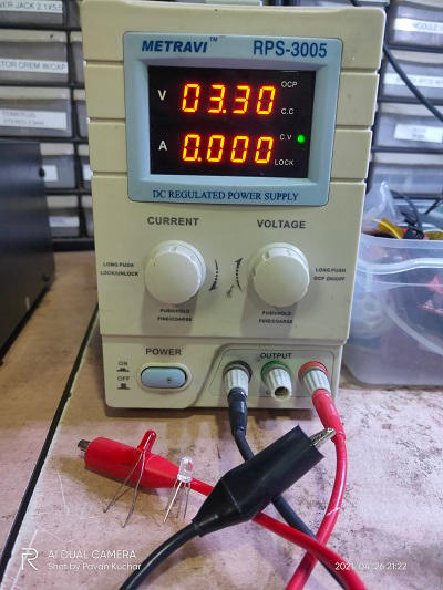
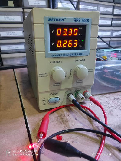
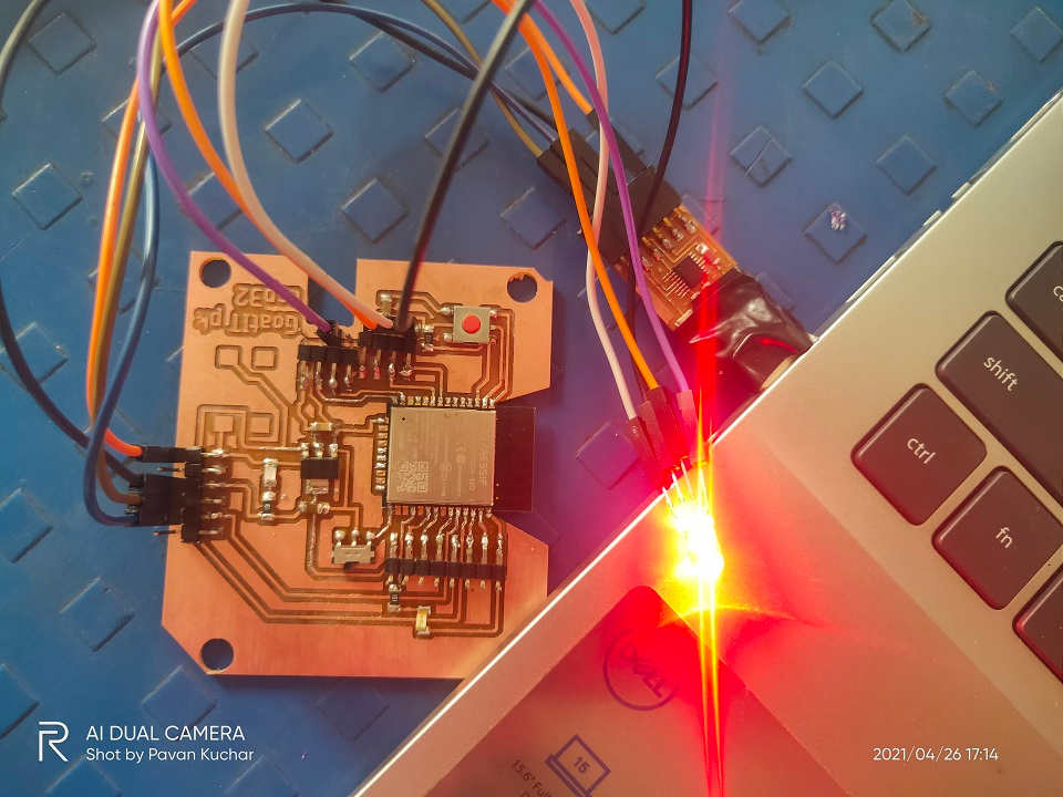
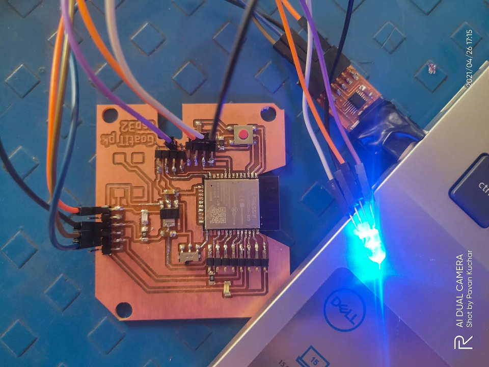
RGB LED as Output Device Testing:
 |  |
|---|---|
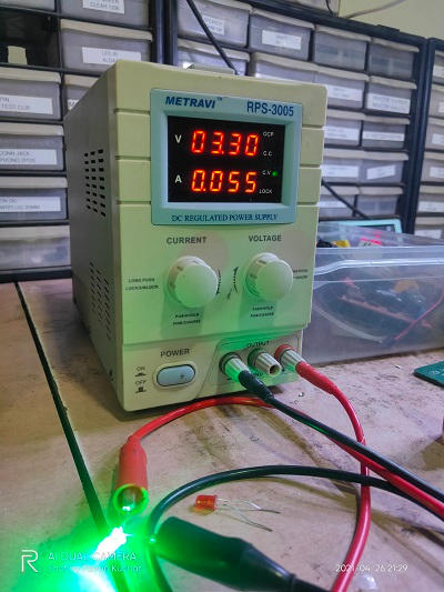 | 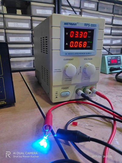 |
Current(mA) readings of RGB LED on 3.3V
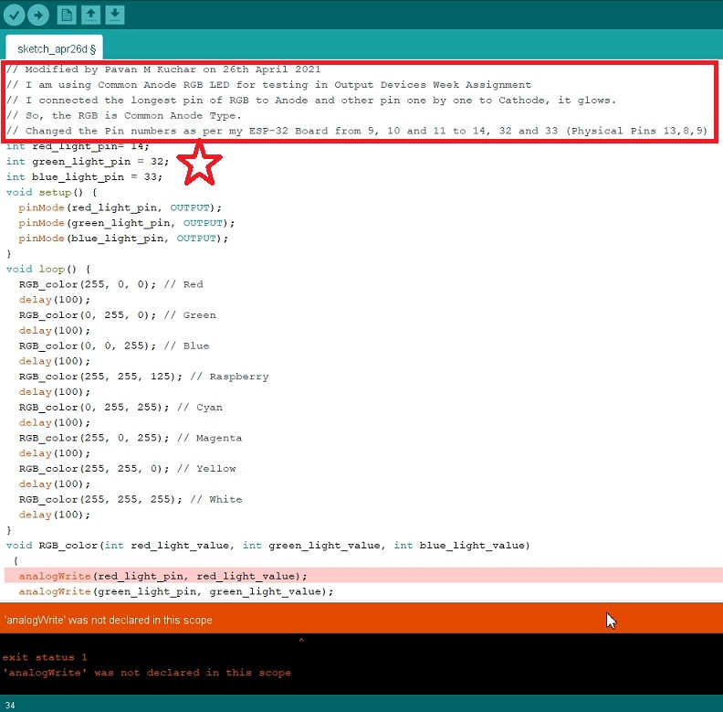
Then I tried to try my hands on the LED and chose the Sketch that I have already ran successfully in the Embedded Programming week. I changed the Pin numbers and compiled but Alas! it didnt worked.
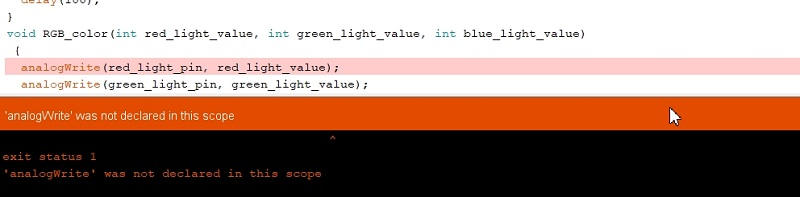
The "analogWrite" command is not supported by ESP-32 uC. But it does support a much better one, the ledcWrite() function. So, I searched on google about it and found the similar good reference on Tech Explorations. The comparision between the Codes for LED Fading is given for Arduino and ESP32 MicroControllers.
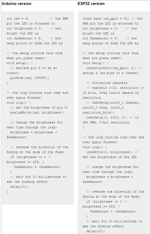
Based on my Understanding, few comparisions are as given below:
| Arduino | ESP-32 |
|---|---|
| The analogWrite() function accepts two parameters: The number of the pin to which the LED is connected The PWM value from 0 to 254 | The ledcWrite() is very similar to analogWrite(). It also requires two parameters: The PWM channel that we want to “write” a value to. The PWM value we want to write to the selected channel. |
| ledcAttachPin(gpio, channel) ledcSetup(channel, frequency, resolution) | |
| a PWM signal is set to 8 bit | it can be whatever you choose, from 1 to 16 bits. |
| The ESP32 contains 16 independent channels. Each of those can be assigned to any PWM-capable pin. This means that you can use any 16 GPIOs to generate PWM output. |
Explanation:
- ledcAttachPin(led_gpio, 0); This binds the PWM channel “0” to GPIO32.
- ledcSetup(0, 4000, 8)-
- The first parameter is “0”. This means that we are configuring the PWM channel “0”.
- The second parameter is 4000, which means that we have chosen the PWM frequency to be 4KHz. The frequency range depends on the resolution you have chosen, but typical values for an 8-bit resolution are from 4KHz to 8KHz. If you are curious about the details, read this.
- The third parameter is “8,” meaning 8 bits. You can set the resolution to any value between 1 and 16 bits.
 |  |
|---|
But still I was not able to do the Color Transition of RGB LED. The code I found was of only Color Fading. I will have to try more to be able to do Color Transition with ESP-32.
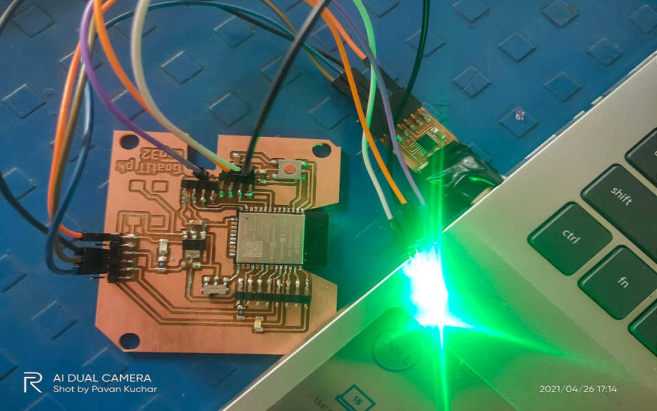
On 29th April, I tried altering the Code for RGB LED Blink by inverting the High and Low commands. (Rahul Kanojia suggested to try) and it worked. I was also able to do the Color Transition without "ledcwrite" command. The Logic being if we Low the Red LED pin, it remains ON(lightened) and meanwhile the other Green LED is also ON and later the Blue LED as well. This allows the Colors to mix and gives the Color Transition like Cyan, Raspberry, Violet, Yellow, Magenta etc. When all the three colors of RGB LED mix, it gives the White color.
Test Codes:First for RGB LED Blink and Other for RGB LED Color Transition
// Modified by Pavan M Kuchar on 26th April 2021 |
// Modified by Pavan M Kuchar on 29th April 2021 |
|---|
Video Stream - RGB LED Color Transition:
Summary:
After this week's assignment, I was able to -
- Know about various Output Devices
- Calculate the Power Consumption of LCD display
- Tested the LCD display and RGB LED on my Board.
- Couldnt test Input and Output Device in combination
Video Streams of Work Uploaded on YouTube:
Downloads: Original Files
The Sketch or Program / Codes used for testing the Output Devices like LCD and LED could be found here for downloading.