

Embedded Networking and Communications:
In this Thirteenth week of Fab Academy, we had to understand about what, how of the Embedded Networking and Communication Protocols.
Objective:
1. Group assignment:
Details here.This week is having the following Objective for the Group-
Send a message between two projects
2. Individual assignment:
design, build, and connect wired or wireless node(s) with network or bus addresses
Learning Outcomes:
Demonstrate workflows used in network design
Implement and interpret networking protocols and/or communication protocols
Checklist:
Linked to the group assignment page ✔
Documented your project. ✔
Documented what you have learned from implementing networking and/or communication protocols. ✔
Explained the programming process/es you used. ✔
Outlined problems and how you fixed them. ✔
Included design files (or linked to where they are located if you are using a board you have designed and fabricated earlier) and original code.
Opening Quotes:
- "The Opposite of Networking is - NOT WORKING" ― Smart
- NETWORK: There is a thing about him data he never tells what is going on in his mind"
1. Group assignment: Details here.
We had to send a message between two Projects. We decided to use Bluetooth/Wifi to do the communication. For this, we referred the Random Nerd Tutorials and executed the Sketch/Code for conducting the I2C communication between two ESP-32 Boards. One of the boards was of Anand and the other one was mine.
We found out the MAC Address of our Boards and then sent and received the data of Temperature, Humidity and Pressure sent from two BME sensors attached to our boards with each other.
The details of the Group Assignment could be found here.
2. Individual assignment:
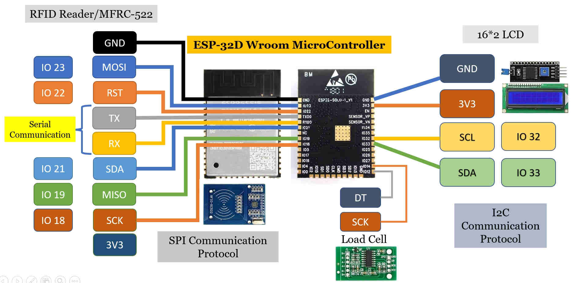
Connections of Sensors and Output Devices with MicroController ESP-32 Board
I have used two sensors namely RFID Reader and Load Cells in my Final Project. Also, I will be using LCD Display as an Output Device.
RFIC/MFRC522 follows the SPI protocol whereas LCD follows the I2C protocol for Communication.
In this assignment, I will try to explain about How does the Communication happens between the MicroController(ESP-32) and these Peripherals.
Here, I will look out for various libraries, commands in the Sketch/Code for defining the Pins; initializing the communication.
Various components needs to interact with each other to exchange data and to issue commands. We can do this by wiring up each and every components with a dedicated set of duplex lines( analogous to a mesh topology).
But, that would increase the number of pins required to a very large number. The solution is to use shared wires connected to each device and only one device can use the these data lines at a time (bus topolgy).
This poses a new problem . Who will use the bus first? What if two devices attempt to access the data at the same time? How will we address a particular device? How can we ask others to wait? That's where different communication protocols comes in. You can think of them as set of rules defining the following:
- How can I address(select) a particular device.
- What is the maximum and minimum data rate possible through this bus.
- What should be signalling scheme( like +5 for to represent a bit one and 0 volt to represent a bit zero eg. NRZ, bipolar, Manchester encoding)
- Is it possible to have more than one master node.(The node which can initiate a transaction)
- What are the control signals? Is it synchronous or Asynchronous. If synchronous what is the clock rate.
OSI Reference Model:The Communications provision moves from the lowest level to the top most layer.
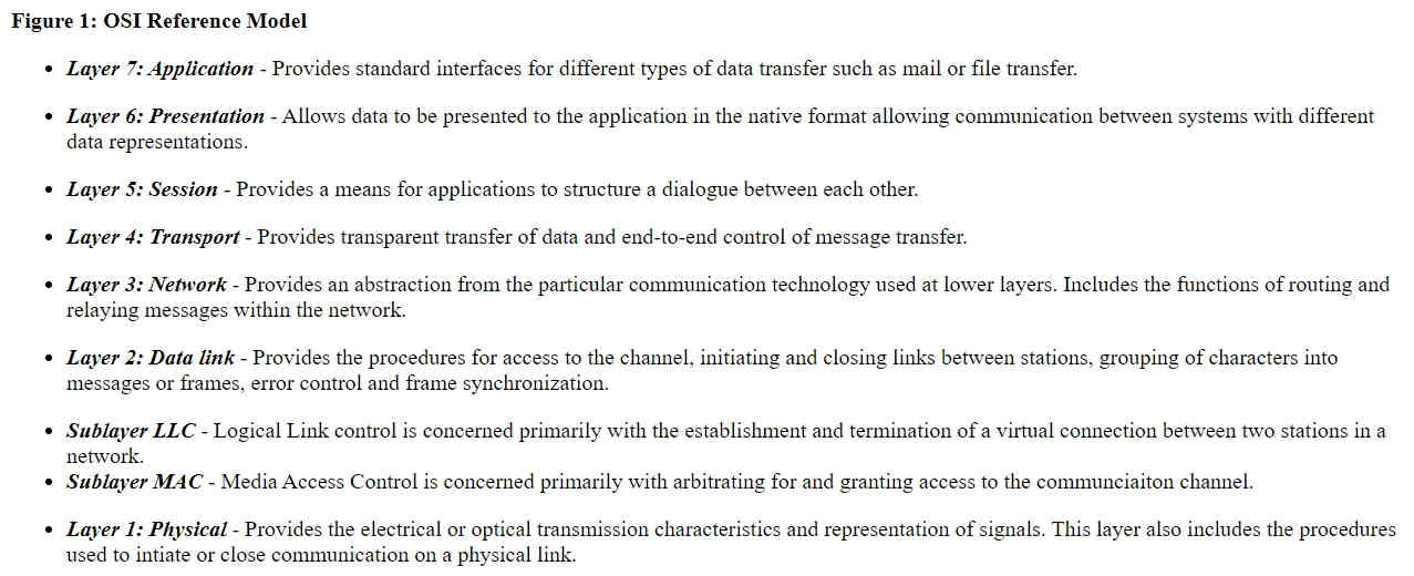
OSI Reference Model
Network:
A “network” is a generic term that refers to a group of entities like objects, peoples, etc., that are connected. “Network” plays a prominent role in embedded systems. For example – routers, gateways, remote process controllers, and sensor networks interact with the networks.
Importance of Networking in Embedded Systems:
The embedded system was originally designed to work on a single device. However, in the current scenario, the implementation of different networking options has increased the overall performance of the embedded system in terms of economy as well as technical considerations.
The most efficient types of the network used in the embedded system are BUS network and an Ethernet network.
A BUS is used to connect different network devices and to transfer a huge range of data, for example, serial bus, I2C bus, CAN bus, etc.
The Ethernet type network works with the TCP/IP protocol.
Examples of embedded networking include CAN, I2C, Component, sensor, and serial bus networking.
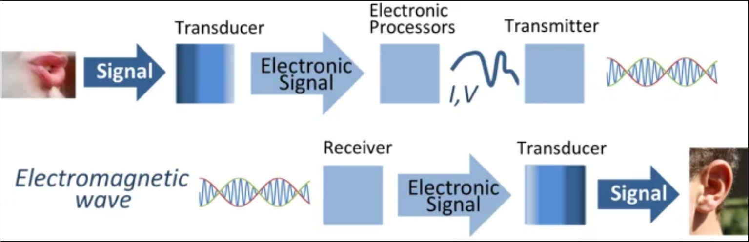
Communication:
It is same as we humans do with each other. There are Languages, Sender, Receiver, Noise, Encoding, Decoding, Transmission Media etc.
SPI, I2C, UART are slower protocols than USB, Ethernet, Bluetooth and Wi-Fi, but they are lot simpler and use less hardware and software resources.
Communication Protocols:
Wired communication protocols are simply a set of rules that allow two or more entities of a communication system to transmit information via physical medium. Therefore, the syntax, semantics, and synchronization of communication and possible error recovery methods between communication systems are all defined by the term “protocol”. Protocols can be implemented by both hardware and software or a combination of both. Further, each protocol has its own application area.
SPI, I2C, UART are ideal for communication between MicroController and Sensors where large amount of data dont need to be tranferred over high speed.
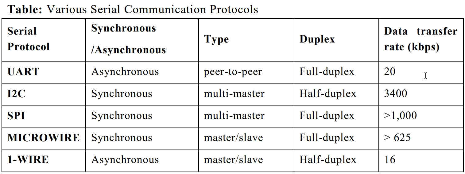
Serial Communication Protocols
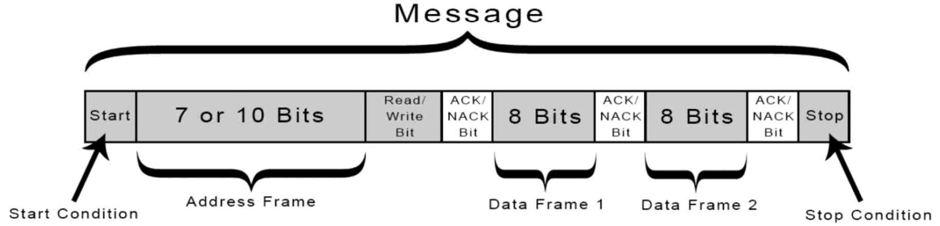
Protocols:It is Rules agreed upon by both Sender and Receiver about How the data is Packed? How many bits constitute a character? When the data begins and Ends?
- Data Communication Types:
- Parallel: data transmitted simultaneously on seperate communication lines. It is used for shorter distance, costly, faster and takes less time
- Serial: data bits transmitted serially one by one i.e. bit by bit on single communication line. It is used for long distance transmission and less costly. It is again of two types:
Asynchronous - transfers single byte at a time and doesn't need Clock Signal
Synchronous - Transfers a block of data(characters)at a time and requires Clock Signal.
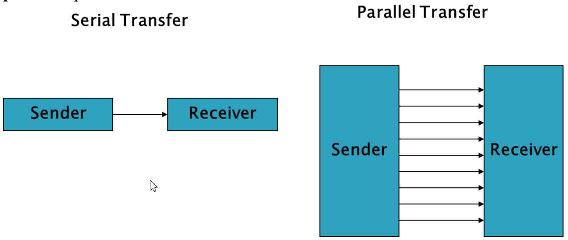
Serial vs Parallel
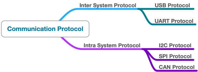
Various Communication Protocols
Inter System Protocol:
Communication between the peripherals through the USB, UART, USART comes under this type. Inter system protocols are communications between two communicating devices i.e. between a PC and development boards, thus communication is via inter bus system.
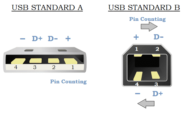
USB
USB Protocols:USB (Universal Serial Bus) Protocols provides a fast master/slave interface using a tiered star topology supporting up to 127 devices with up to 6 tiers. A PC is generally the master or host and each of the peripherals linked to it act as slaves or devices. USB 1.X and 2.X, use 4 lines, Vcc, Ground, and D+/D-, a twisted pair of data lines using NRZI (Non-Return to Zero Invert) encoding, as the USB pinout shown below. Data is transmitted in the form of packets, which is composed of 8 bits (1 byte) with the LSB (Least Significant Bit) transmitted first.
| Advantages | DisAdvantages |
|---|---|
| 1. Fast and simple 2. Plug and play functionality 3. Near universal adoption | 1. Requires powerful master device 2. Specific drivers are required |
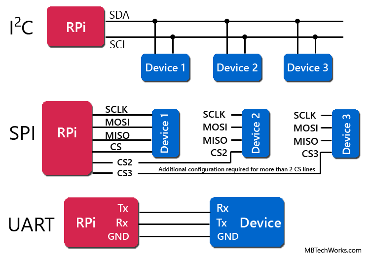
UART:Universal Asynchronous Receiver/Transmitter (UART) is not a communication protocol but a physical circuitry that converts parallel data into serial data. In UART communication, two UARTS communicate directly with each other. The transmitter UART converts data from a controlling device like a CPU into serial form, transits it in serial to the receiving UART, which then converts the serial data back into parallel data for the receiving device.
Only two wires are needed to transmit data between two UARTs; data flows from Tx pin of the transmitting UART to the Rx pin of the receiving UART. UART transmits data asynchronously, which means that no clock signal is needed in transmitting and receiving data. Thus, UART uses start and stop bits with actual data bits. When the receiving UART detects a start bit, it starts to read the incoming bits at a specific frequency known as the baud rate. Both UARTs must operate at about the same baud rate. The baud rate between the transmitting and receiving ends can only differ by about 10% before the timing of bits gets too far off.
| Advantages | DisAdvantages |
|---|---|
| 1. Only requires two wires 2. No clock signal is necessary 3. Cost effective | 1. The size of the data frame is limited to a maximum of 9 bits 2. Doesn’t support multiple master/slave functionality |
Comparison between Various Inter System Communication Protocols:
| UART | USART | USB |
|---|---|---|
| The term UART stands for Universal Asynchronous Transmitter and Receiver | The term USART stands for Universal Synchronous and Asynchronous Data Transmitter and Receiver | The term USB stands for Universal Serial Bus |
| UART mainly includes two wire-based protocols like transmitter and receiver | USART is a two-wire protocol like Transmitter and Receiver | USB is a two-wire protocol like D+ & D- |
| It transmits as well as receives pockets of data by byte without classes pulse | It transmits and receives a block of data through classes pulses | It transmits and receives the data through clock pulses |
| UART is a half-duplex communication | USART is a full-duplex communication | USB is also full-duplex communication |
| UART is slow as compared to USART | USART is slow as compared to USB | It is fast as compared to USART and UART |
Communication Protocols
Intra System Communication Protocols:
The Intra system protocol establishes communication between components within the circuit board. In embedded systems, intra system protocol increases the number of components connected to the controllers.
On device communication protocols are known as intra system communication protocols. These are used in scenarios such as sending a sensor’s value to an MCU. Most of the Grove Modules communicate via these protocols.
SPI, I2C and CAN falls under this category.
| I2C | SPI | CAN |
|---|---|---|
| I2C is an inter-integrated circuit | SPI stands for serial peripheral interface | The CAN stands for controller area network |
| It is implemented by Philips | SPI is developed by Motorola | CAN is developed by Bosch |
| I2C is a half-duplex protocol | SPI is a full-duplex protocol | CAN is a full-duplex protocol |
| It is a two-wire protocol like SCL and SDL | It is a four-wire protocol like SCL, MISO, MOSI and SS | It is a two-wire protocol like CANH+ and CAN H- |
| It is a multi-master protocol | It is a single master protocol | It is a multi-master protocol |
SPI Communication in my Final Project:
I will be using 13.56 MHz RFID Reader (MFRC522) to identify the Goats. RFID uses the SPI Communication Protocol. I will try to explain how does the Communication happens in this case. I will do this with the help of Sketch/Code in Arduino IDE, Commands and Libraries, Pin outs used for Communication.
SPI Communication Process
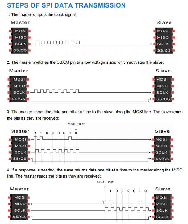
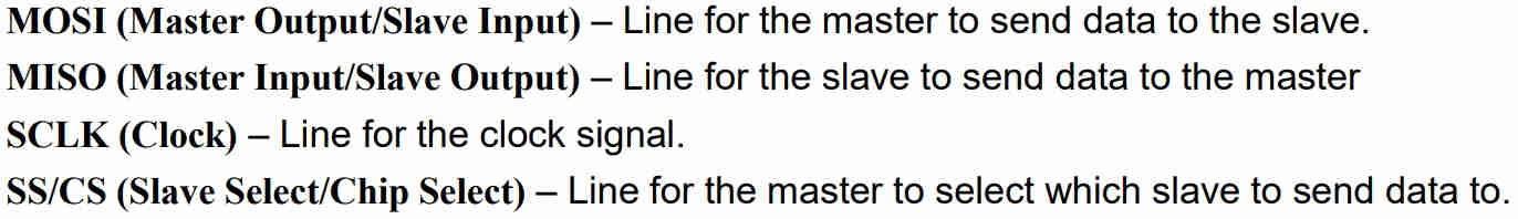
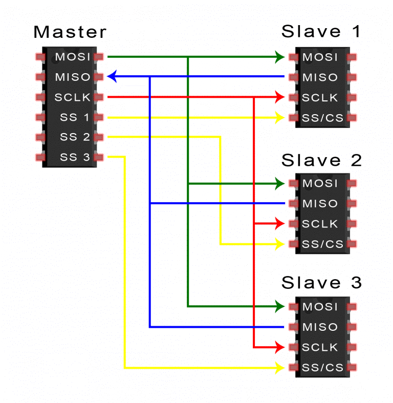
Serial Peripheral Interface (SPI):SPI (Serial Peripheral Interface) is a common communication protocol used by many different chipsets. Devices which communicate via SPI are in a master/slave relationship. The master is the controlling device (usually a micro-controller) while the slave (usually a sensor, display, or memory chip) takes instruction from the master. SPI uses 4 wires named MOSI (Master Out Slave In), MISO (Master In Slave Out, SS (Slave Select), and SCLK (Serial Clock). Further, the SS line is used to select the appropriate slave by pulling the SS low where it is normally held high. If the SS line is low the chip will begin to take instruction from the master. However a master must have multiple GPIO pins available if it is to speak with multiple slaves. To get around this, some devices will use a multiplexor to select the slaves.
SPI is full-duplex, meaning it is able to send and receive data simultaneously. While the master is providing new instructions or information via the MOSI line, the slave can return messages or results via the MISO line. This allows for faster overall throughput.
The RFID Reader in my Final Project follows the SPI Communication Protocol.
SPI Pins
Serial Peripheral Interface (SPI)
#include MFRC522.h
#define RST_PIN 22 // Configurable, see typical pin layout above
#define SS_PIN 21 // Configurable, see typical pin layout above
MFRC522 mfrc522(SS_PIN, RST_PIN); // Create MFRC522 instance
void setup()
{
Serial.begin(9600); // Initialize serial communications with the PC
while (!Serial); // Do nothing if no serial port is opened (added for Arduinos based on ATMEGA32U4)
SPI.begin(); // Init SPI bus
mfrc522.PCD_Init(); // Init MFRC522
delay(4); // Optional delay. Some board do need more time after init to be ready, see Readme
mfrc522.PCD_DumpVersionToSerial(); // Show details of PCD - MFRC522 Card Reader details
Serial.println(F("Scan PICC to see UID, SAK, type, and data blocks..."));
}
void loop()
{
// Reset the loop if no new card present on the sensor/reader. This saves the entire process when idle.
if ( ! mfrc522.PICC_IsNewCardPresent()) {
return;
}
// Select one of the cards
if ( ! mfrc522.PICC_ReadCardSerial()) {
return;
}
// Dump debug info about the card; PICC_HaltA() is automatically called mfrc522.PICC_DumpToSerial(&(mfrc522.uid));
}
Result of the RFID SPI Communication Protocol Sketch Run in Arduino IDE:
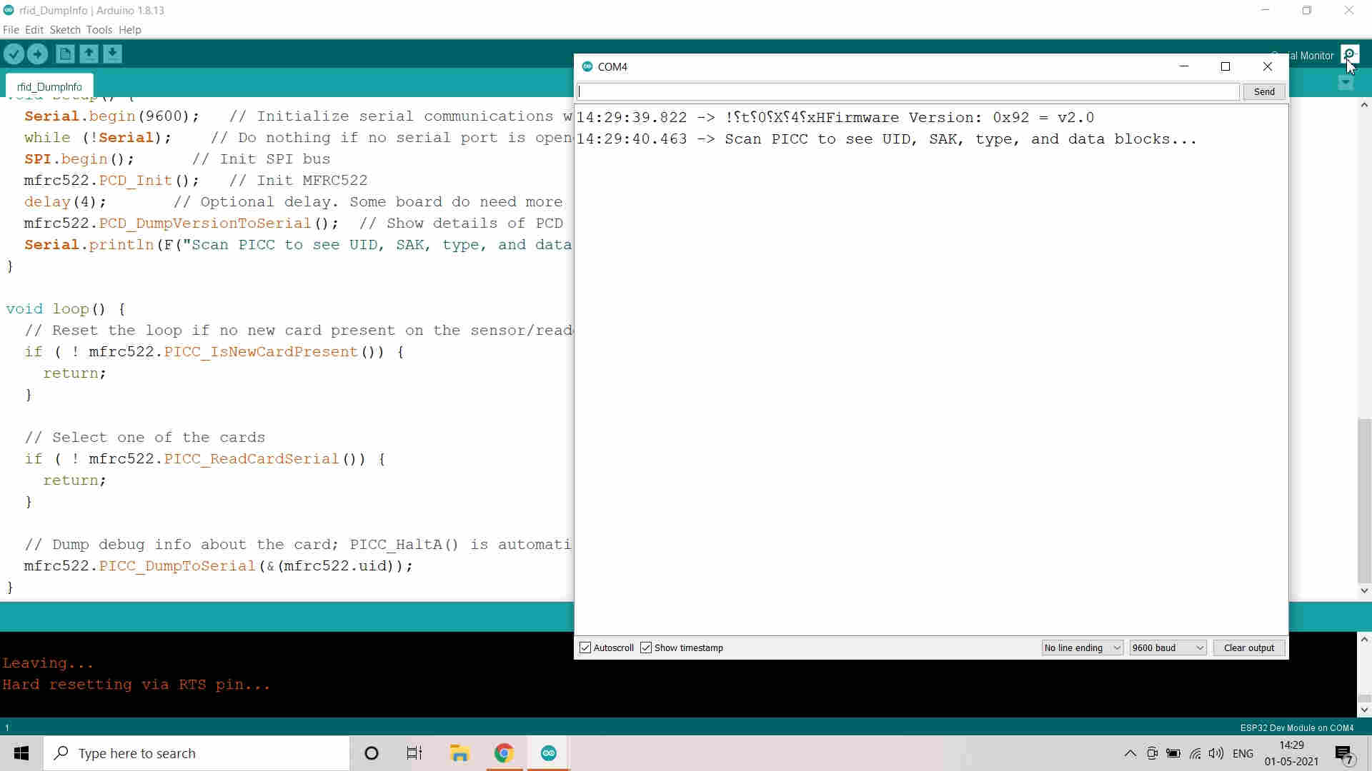
Tested Rfid Dump Info Code
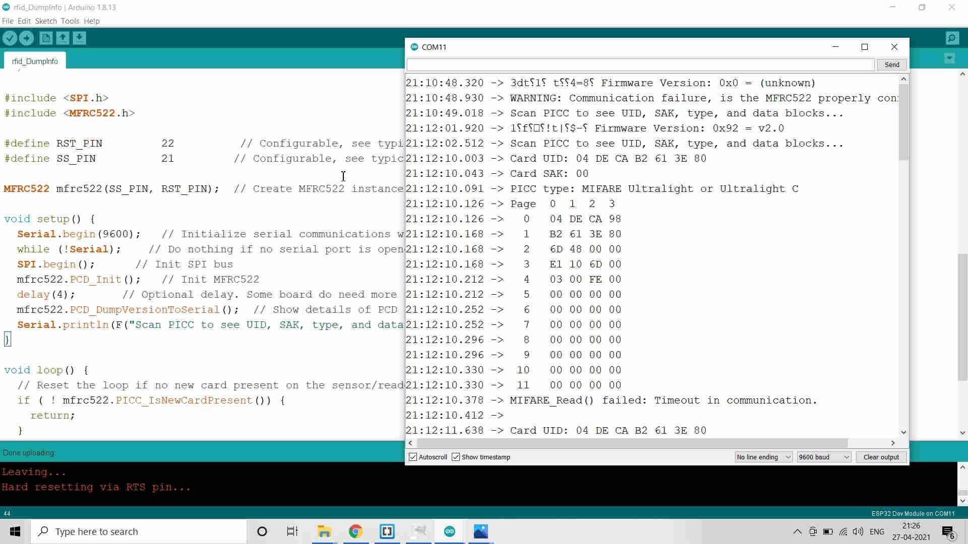
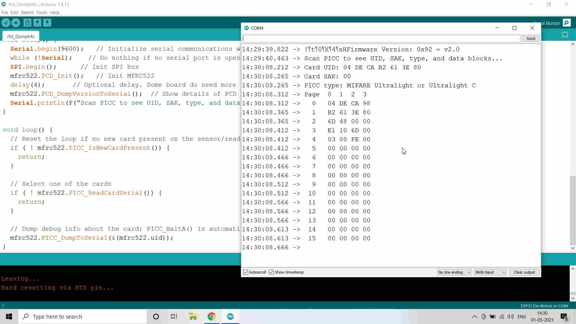
Successfully Scanned the RFID Tag
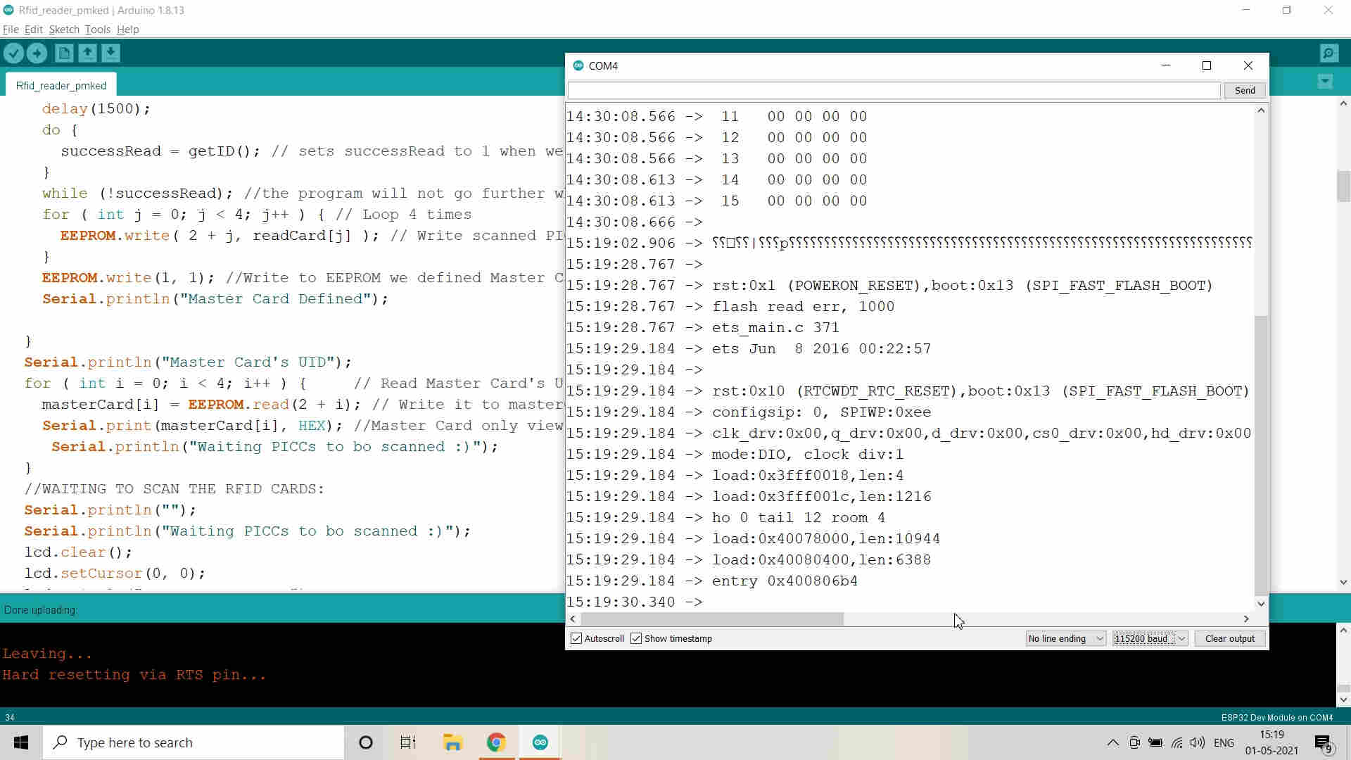
Edited the Code to integrate with LCD
Successfully compiled the Code and Verified
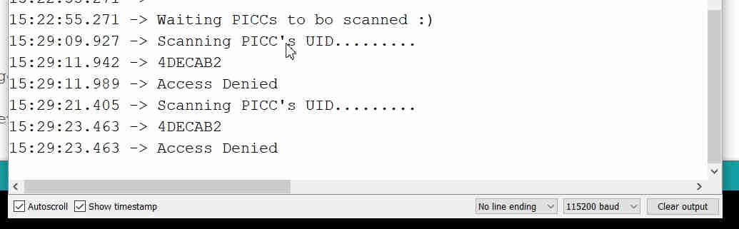
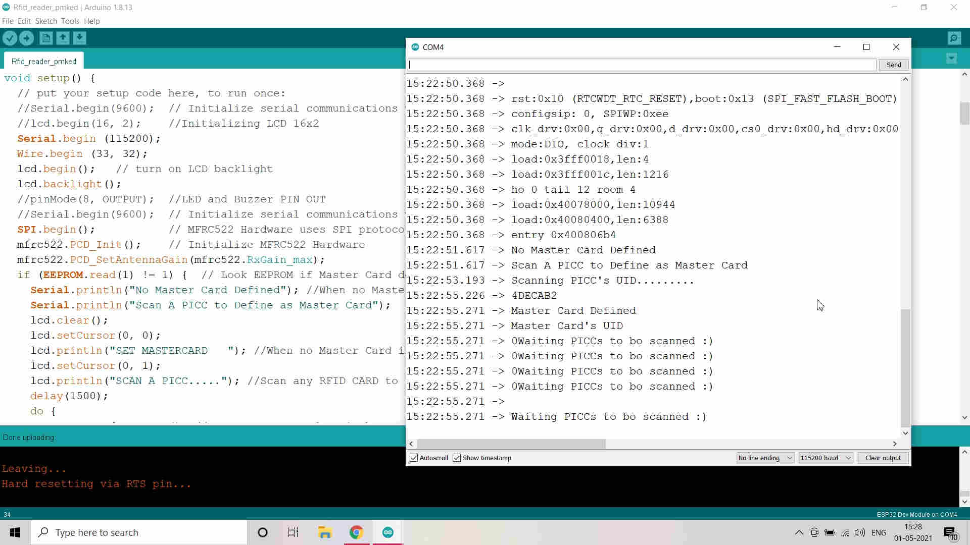
Scanned the Tag which is not Master Tag and thats why Access denied
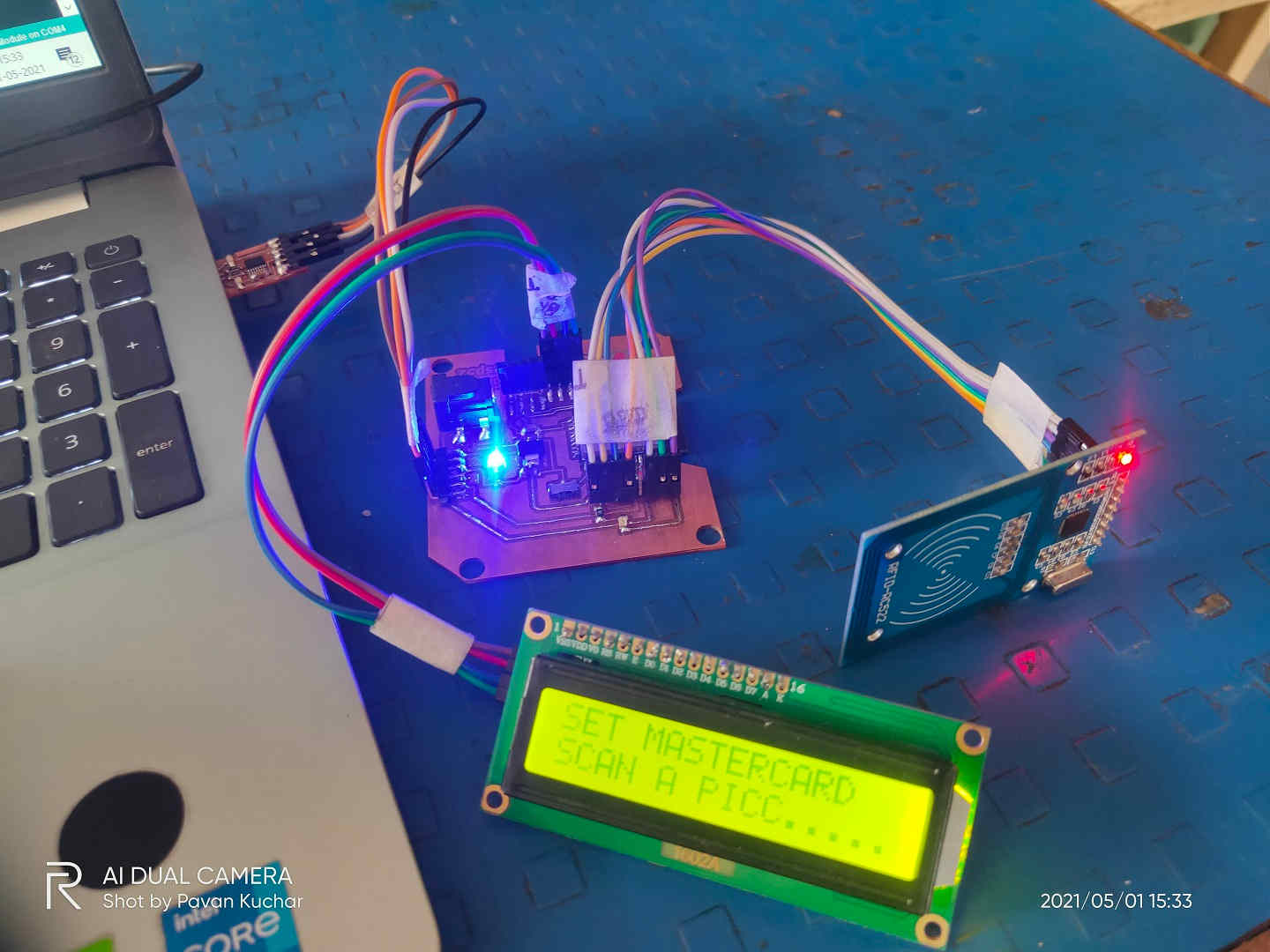
RFID (SPI) and LCD (I2C) connected with ESP-32 board
How does the Code Work and the Communication happens:
The first thing I did is including some libraries. So, we will need to include the previously installed MFRC522.h library, for getting all the functionality needed to interact with the device.
Since we will communicate with the RFID card reader via the SPI protocol, we will also need to include the SPI.h library.
#include <MFRC522.h>
Then we will continue our code by defining some constants, more precisely the number of the Slave Select (SS) pin and the number of the reset pin. I’ve assigned the ESP32 pin 22 as reset pin and pin 21 as Slave Select pin, although I could have used others.
const int resetPin = 22; // Reset pinconst int ssPin = 21; // Slave select pin
Next, we will need to create an object of class MFRC522, which will expose the methods we will need to interact with the RFID reader. We will passas inputs of the constructor both the ssPin and the resetPinvariables we just defined.
MFRC522 mfrc522 = MFRC522(ssPin, resetPin); // Create instanceMoving on to the Arduino setup function, we will now initialize the Serial port, so we can print the information we will obtain from the device. We will also initialize the SPI interface, so we are then able to communicate with the MFRC522.
Serial.begin(115200);SPI.begin();
Next, we need to initialize the MFRC522 device. Fortunately, this library hides the low level details for us and thus we simply need to call the PCD_Init method of the mfrc522 object we instantiated early. This method call takes no arguments and returns void.
mfrc522.PCD_Init();Now that we have handled the initialization, we will finally print the version of the firmware to the serial port. Again, this is done by simply calling a method of the mfrc522 object. So, we call the PCD_DumpVersionToSerial method, which receives no arguments and also returns void.
Note that this method will print the information to the serial port for us, which is why it returns void.
I2C Communication in my Final Project:
I will be using 16*2 LCD to display the measured Weight of the Goats. LCD uses the I2C Communication Protocol. I will try to explain how does the Communication happens in this case. I will do this with the help of Sketch/Code in Arduino IDE, Commands and Libraries, Pin outs used for Communication.
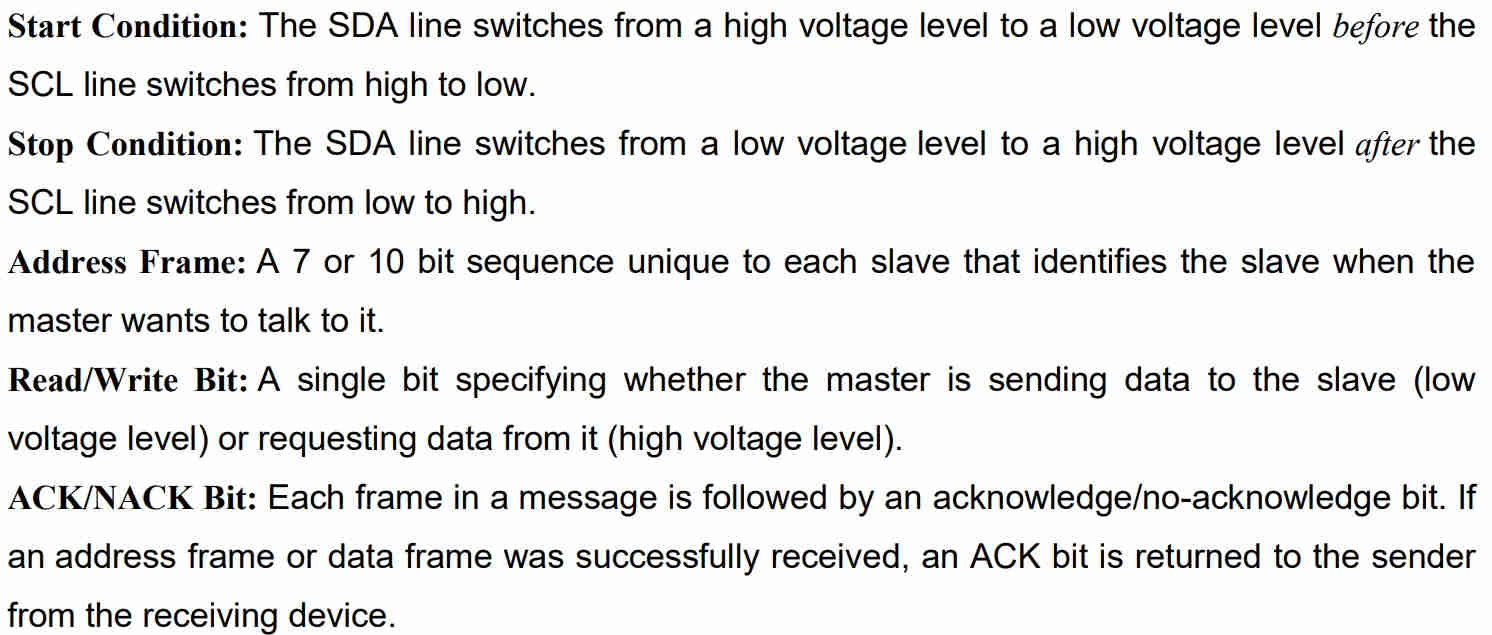
Inter Integrated Circuit (I2C) Communication Protocol:(I2C) Inter Integrated Circuit, pronounces “eye-two-see” or “eye-squared-see”, combines the best features of SPI and UART. With I2C, you are able to connect multiple slaves to a single master (just like SPI) or having multiple masters controlling single or even multiple slaves. This is extremely useful when you are logging data into a single LCD from more than one micro-controller.
Similar to UART, I2C only uses two wires to transmit data between devices: SDA(Serial Data) and SCL(Serial Clock). Like SPI, I2C is synchronous, so the output of the bits is synchronized to the sampling of bits by a clock signal shared between the master and the slave. The clock signal is always controlled by the master.
Detail information about I2C communication in ESP-32 could be foung here.

Pins in I2C Communication
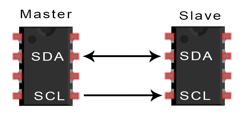
Inter Integrated Circuit (I2C) Communication Protocol
Test Code:
// Adapted from the code by
// Rui Santos
// https://randomnerdtutorials.com
// Modified by - Pavan M. Kuchar on 26th April 2021
#include LiquidCrystal_I2C.h>
#include Wire.h>
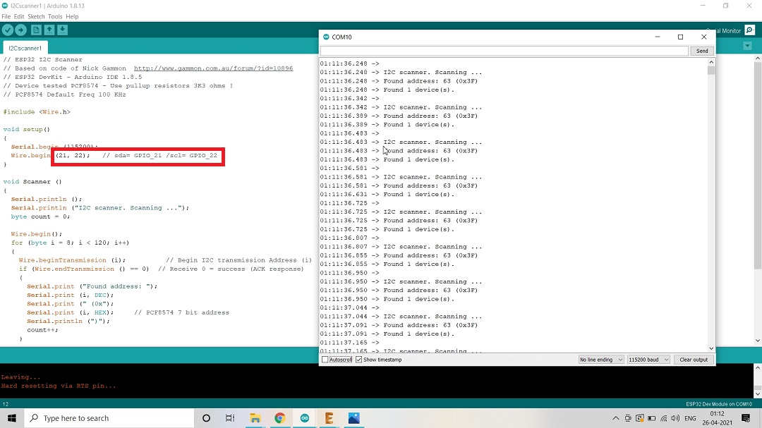
// if you don't know your display address, run an I2C scanner sketch
LiquidCrystal_I2C lcd(0x3F, 16, 2);
String messageStatic = "Hello World"; //Static Message
String messageToScroll = "I m Pavan Kuchar at FAB21"; //This is a scrolling message with more than 16 characters
// Function to scroll text
// The function acepts the following arguments:
// row: row number where the text will be displayed
// message: message to scroll
// delayTime: delay between each character shifting
// lcdColumns: number of columns of your LCD
void scrollText(int row, String message, int delayTime, int lcdColumns) {
for (int i=0; i < lcdColumns; i++) {
message = " " + message;
}
message = message + " ";
for (int pos = 0; pos < message.length(); pos++) {
lcd.setCursor(0, row);
lcd.print(message.substring(pos, pos + lcdColumns));
delay(delayTime);
}
}
void setup(){
Serial.begin (115200);
Wire.begin (33, 32);
// initialize LCD
lcd.begin();
// turn on LCD backlight
lcd.backlight();
}
void loop(){
// set cursor to first column, first row
lcd.setCursor(0, 0);
// print static message
lcd.print(messageStatic);
// print scrolling message
scrollText(1, messageToScroll, 250, 16);
}
How does the Communication happens:
I2C Working Process
How does the Code Work and the Communication happens:
I2C Communication Process
How does the Code Works?
First, you need to include the LiquidCrystal_I2C library.
#include <LiquidCrystal_I2C.h>
The next two lines set the number of columns and rows of your LCD display. If you’re using a display with another size, you should modify those variables.
int lcdColumns = 16;
int lcdRows = 2;
Then, you need to set the display address, the number of columns and number of rows. You should use the display address you’ve found in the previous step.
LiquidCrystal_I2C lcd(0x27, lcdColumns, lcdRows);
In the setup(), first initialize the display with the init() method.
lcd.init();
Then, turn on the LCD backlight, so that you’re able to read the characters on the display.
lcd.backlight();
To display a message on the screen, first you need to set the cursor to where you want your message to be written. The following line sets the cursor to the first column, first row.
lcd.setCursor(0, 0);
Note: 0 corresponds to the first column, 1 to the second column, and so on…
Then, you can finally print your message on the display using the print() method.
lcd.print("Hello, World!");
Wait one second, and then clean the display with the clear() method.
lcd.clear();
After that, set the cursor to a new position: first column, second row.
lcd.setCursor(0,1);
Then, the process is repeated.
So, here’s a summary of the functions to manipulate and write on the display:
- lcd.init(): initializes the display
- lcd.backlight(): turns the LCD backlight on
- lcd.setCursor(int column, int row): sets the cursor to the specified column and row
- lcd.print(String message): displays the message on the display
- lcd.clear(): clears the display
Result of the LCD I2C Communication Protocol Sketch Run in Arduino IDE:
Tried the Sketch/Code with the Default pins mentioned in the Code and Voila! it worked.
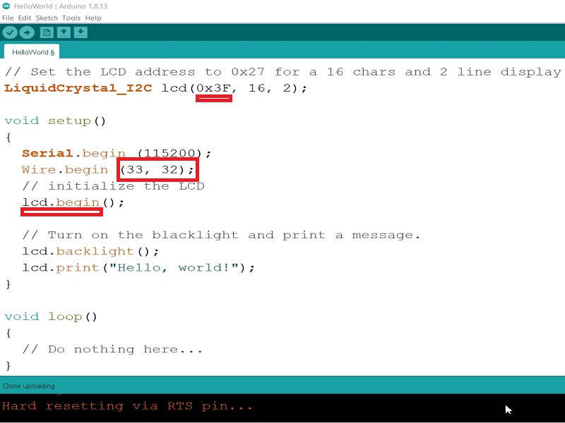
Took the Hello World Example from the Library and defined Pins and I2C Display Address
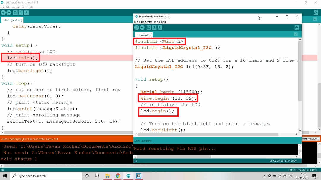
Tried the Scroll Text Example but it didnt worked. Compared the Sketch that worked and found that "lcd.init" was not mentioned in the library. May be the libraries in the programs are different.
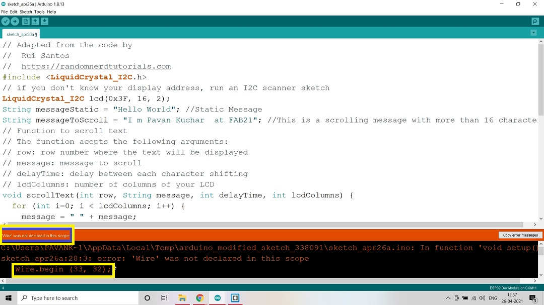
Even "wire.begin" was not declared in the command of Library.
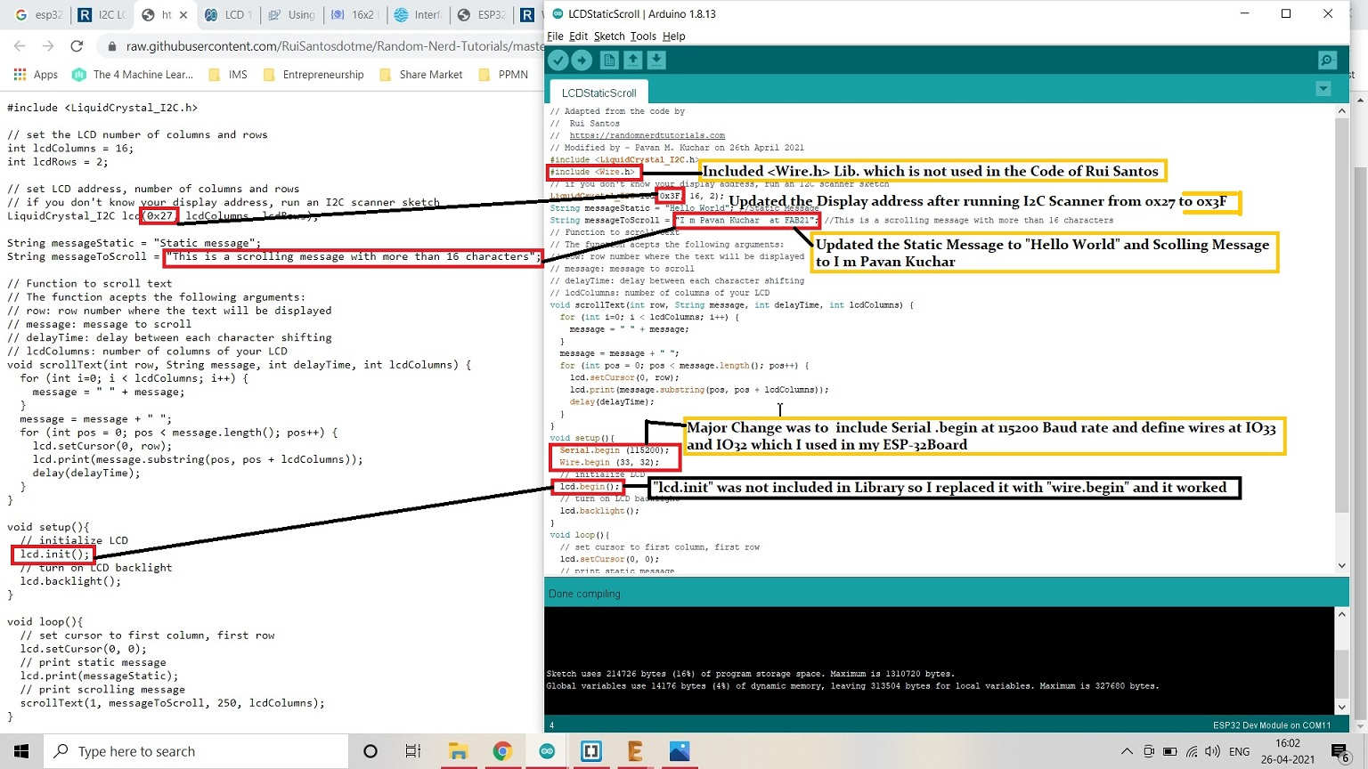
Took the Code from Rui Santos on Random Nerd Tutorials and changed few entries.
Video Stream - 16*2 LCD Display:
CAN (Controller Area Network) Protocols:CAN protocol can be defined as the set of rules for transmitting and receiving messages in a network of electronic devices. It was designed for robust and flexible performance in harsh environments, and particularly for industrial and automotive application.
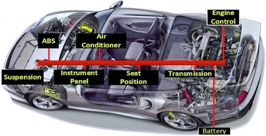
CAN (Controller Area Network) Protocol
Defence Mechanism Against Various Communication Failures:
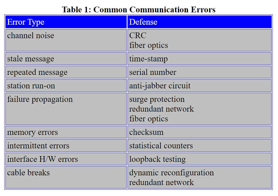
Defence Mechanism in Communication Errors
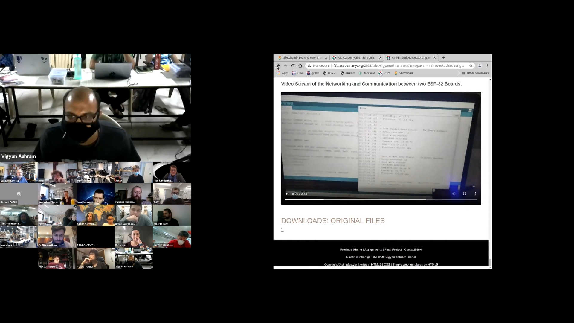
Video Stream of the Networking and Communication between two ESP-32 Boards:
My Global Review:
I was reviewed Globally by Dr. Neil on 5th May 2021 for this week. Recording of my review is from 1 hour 14th minute. The link for the video of review is given here.
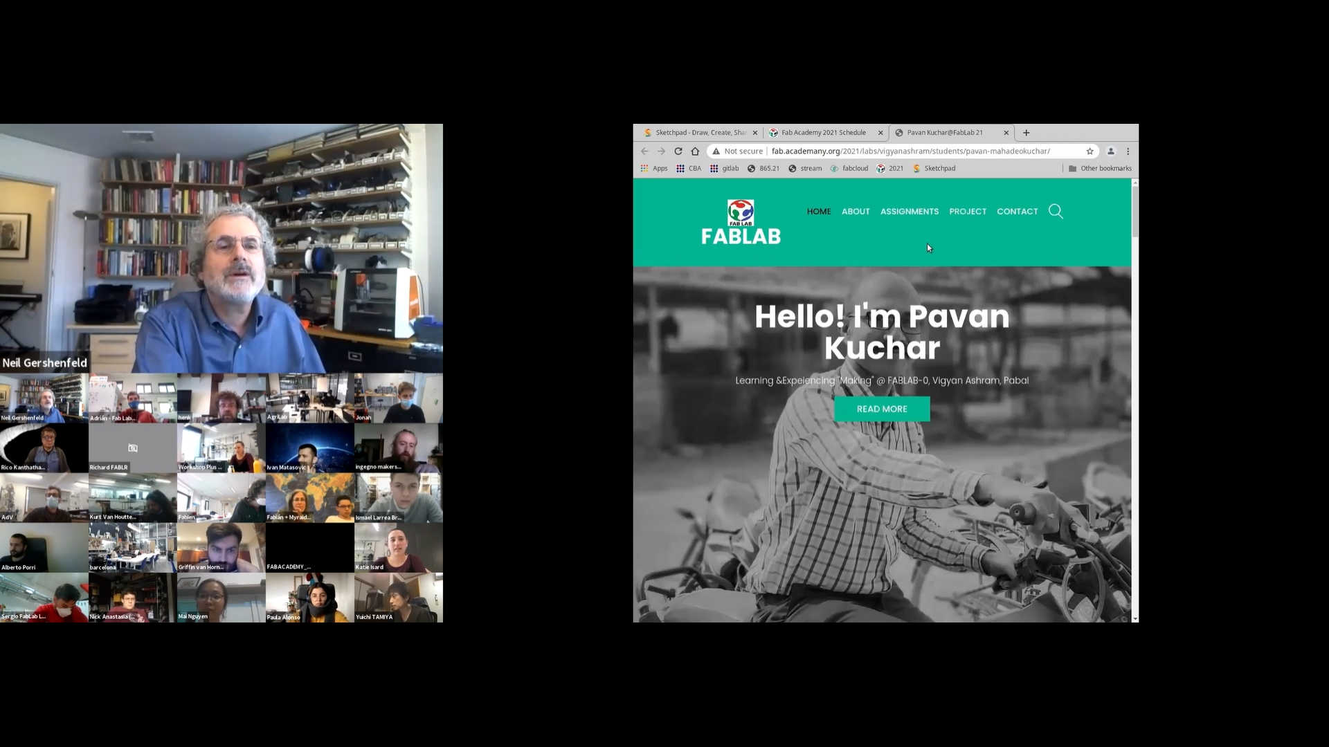
My Review at 1 Hour 15 min.
My Review at 1 Hour 15 min. in the Video Timeline
Downloads: Original Files
Original Codes/Sketches that I used for Networking and Communication of SPI and I2C Protocols on RFID and LCD respectively could be found here.