

Computer Controlled Cutting:
Objective:
1. Group assignment:
The details of the Group Assignment could be found here.
Characterize your laser cutters focus, power, speed, rate, kerf, and joint clearance document your work (individually or in group)
2. Individual assignment:
1. Design, laser cut, and document a parametric press-fit construction kit, which can be assembled in multiple ways. Account for the laser cutter kerf.
2. Cut something on the vinyl cutter
Learning Outcomes:
Demonstrate and describe parametric 2D modelling processes
Identify and explain processes involved in using the laser cutter.
Develop, evaluate and construct the parametric construction kit
Identify and explain processes involved in using the vinyl cutter.
Checklist:
linked to the group assignment page
Explained how you parametrically designed your files
Documented how you made your press-fit kit
Documented how you made your vinyl cutting
Included your original design files
Included your hero shots
Opening Quote:
"If Laser beams can cut through mountains, why should we doubt the power of Prayers?"
Computer Controlled Cutting:
The task of this week included assignments to be done in group and individually. We have to use Laser Cutter and Vinyl cutter. For two weeks, we have been only working on the laptops. From now on, we will be making our hands dirty on the machines and learning to fabricate with the CNC machines.
Group Assignment:
For the Group assignment, we had to Characterize your laser cutter’s focus, power, speed, rate, kerf, and joint clearance document your work (individually or in group).
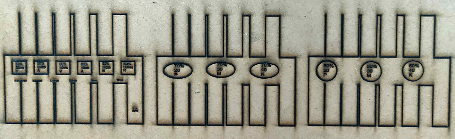
We have designed a Comb like design having 6 squares with variation in Speed and Power to calculate the kerf of the machine on various materials.
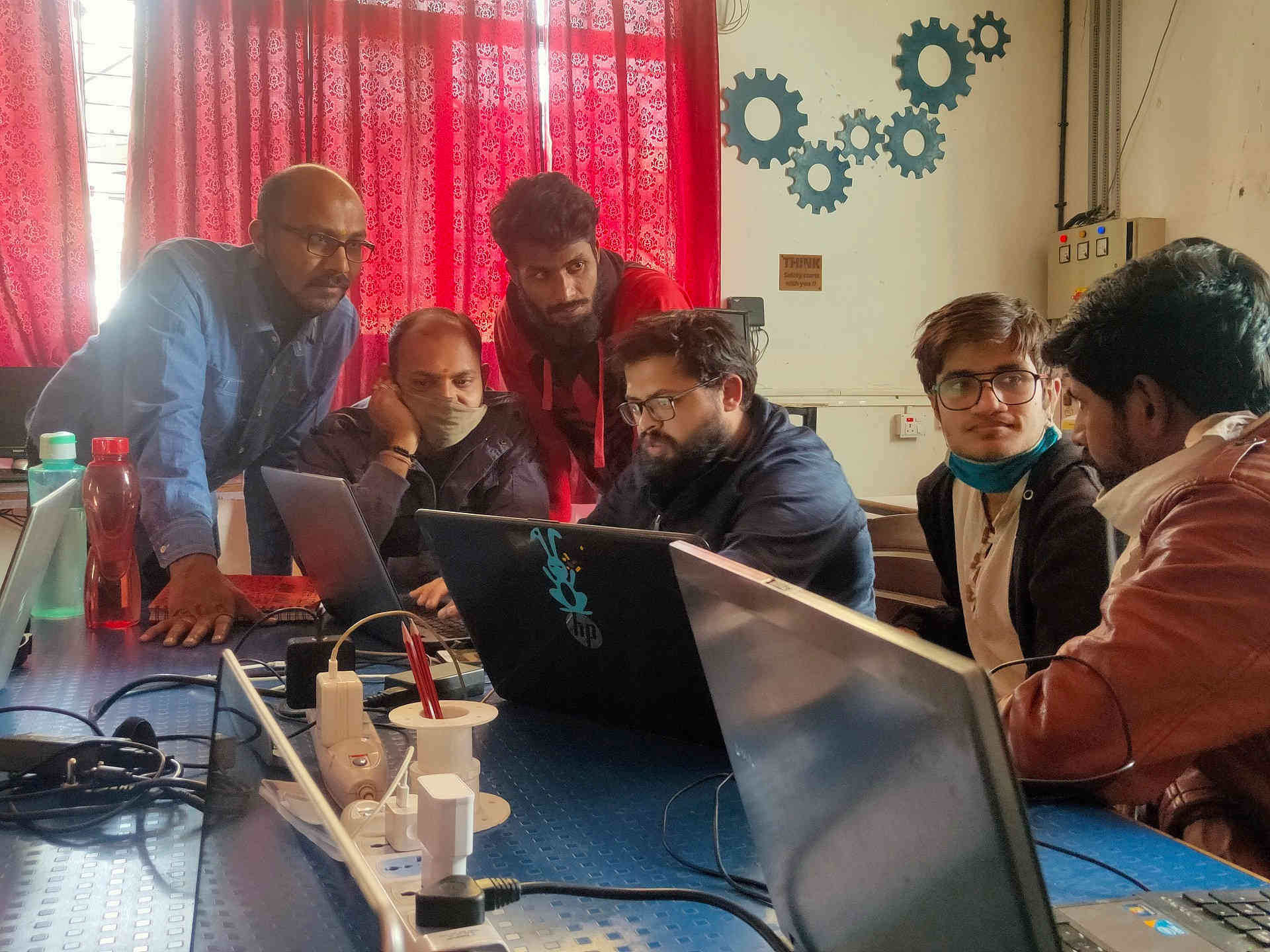 Planning the Modus Operandi of the Group Assignment | 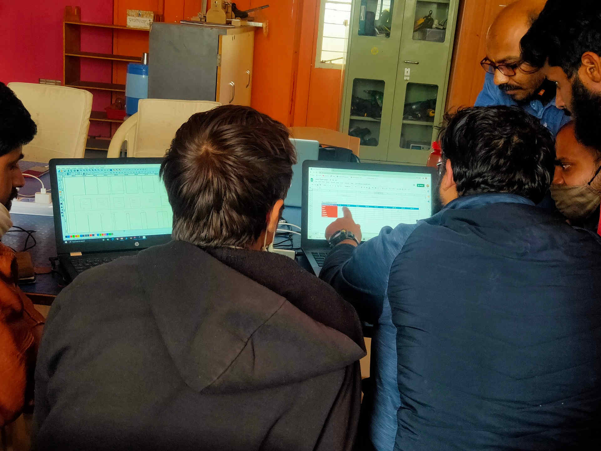 Preparation of Google Sheet for Data Sharing |
|---|---|
 Trial Operation of Laser Cutter | 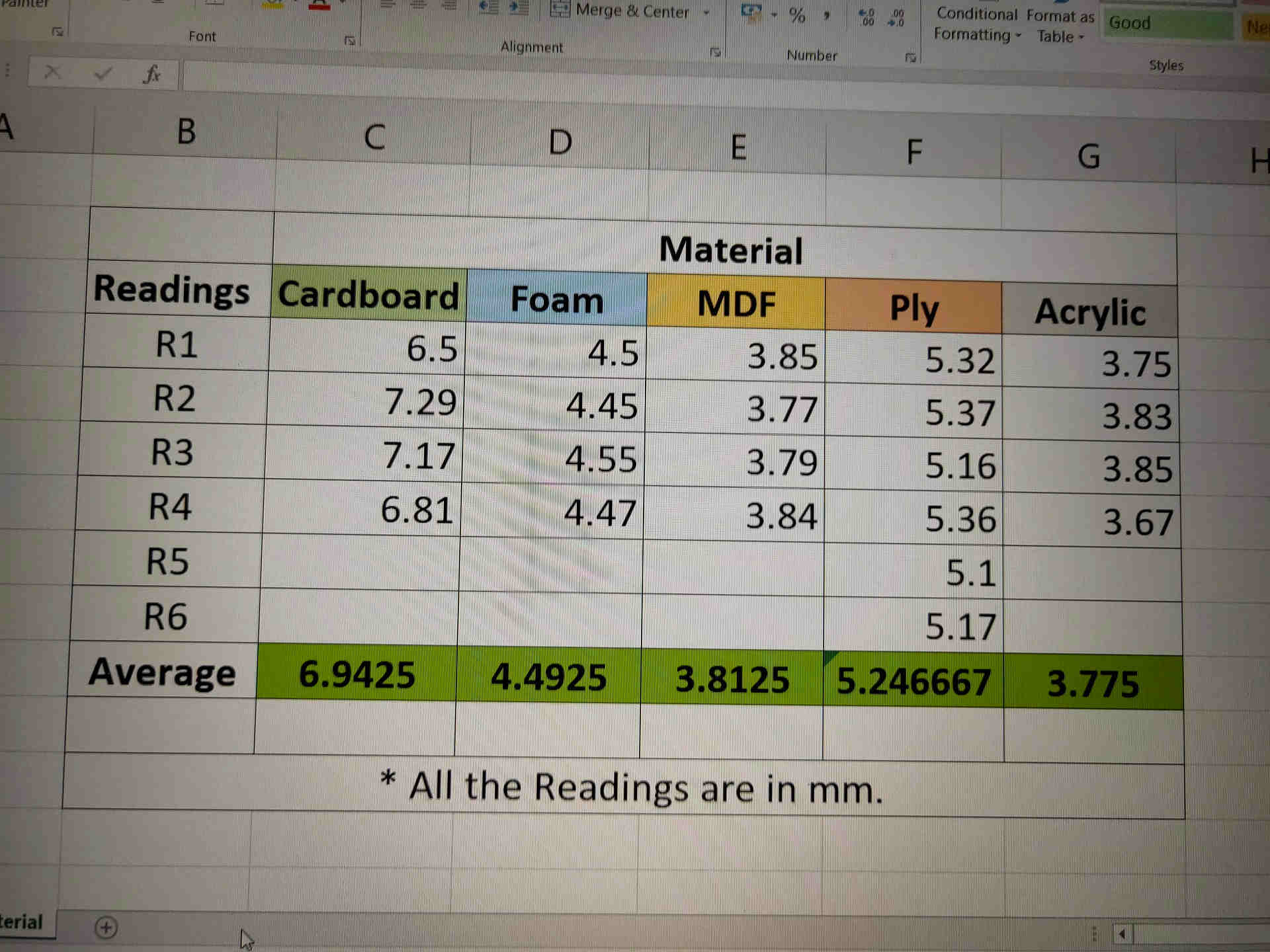 Dimension Readings of various Test Materials |
We have divided the materials amongst us. The material used by us for the kerf calculation were Cardboard (6.91 mm thick), MDF i.e. Medium Density Fiber (3.81 mm thick), Foam (4.49 mm thick), Plywood (5.25 mm thick) and Acrylic (3.75 mm thick). I have taken the reading for the MDF material. These reading were then documented in a Google Sheet circulated earlier. The consolidated results were then collectively presented in the Group assignment.
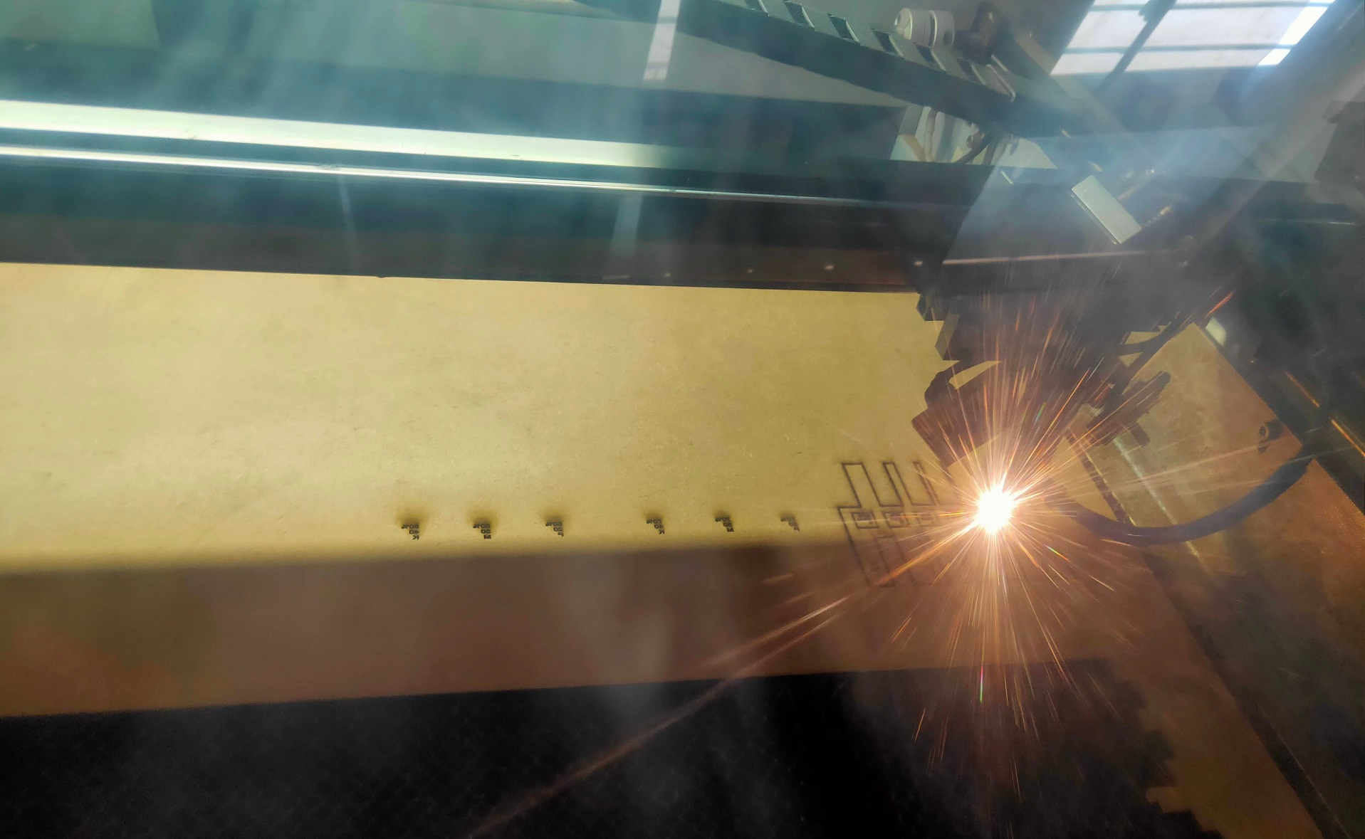
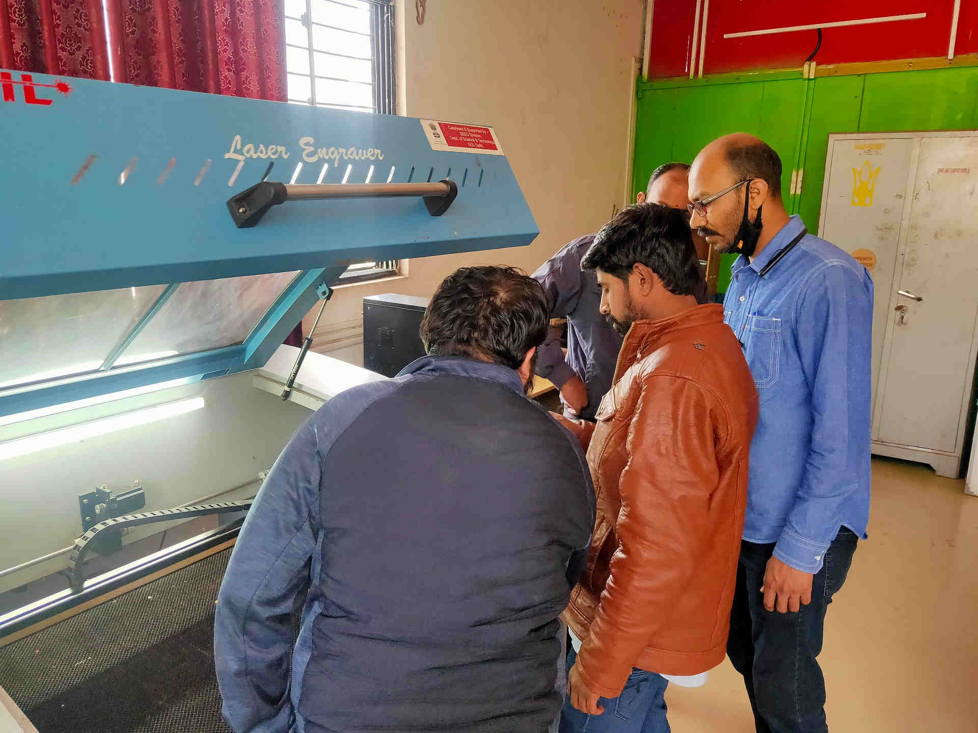
Lase Cutting the Test on MDF material
Summary:
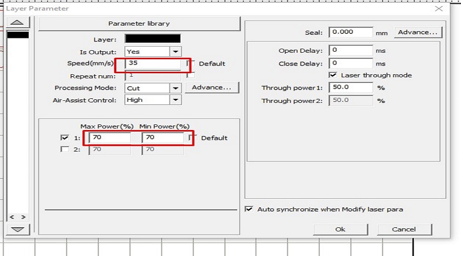
After various combinations of power and speed for MDF, I found out that the MDF of 3.81 mm thickness needs to be cut at the Speed of 10 mm/sec and power of 70% because when I cut the MDF with the Power of 50, 60 and 70% with speeds from 20 to 40 mm/s, it was not cut.
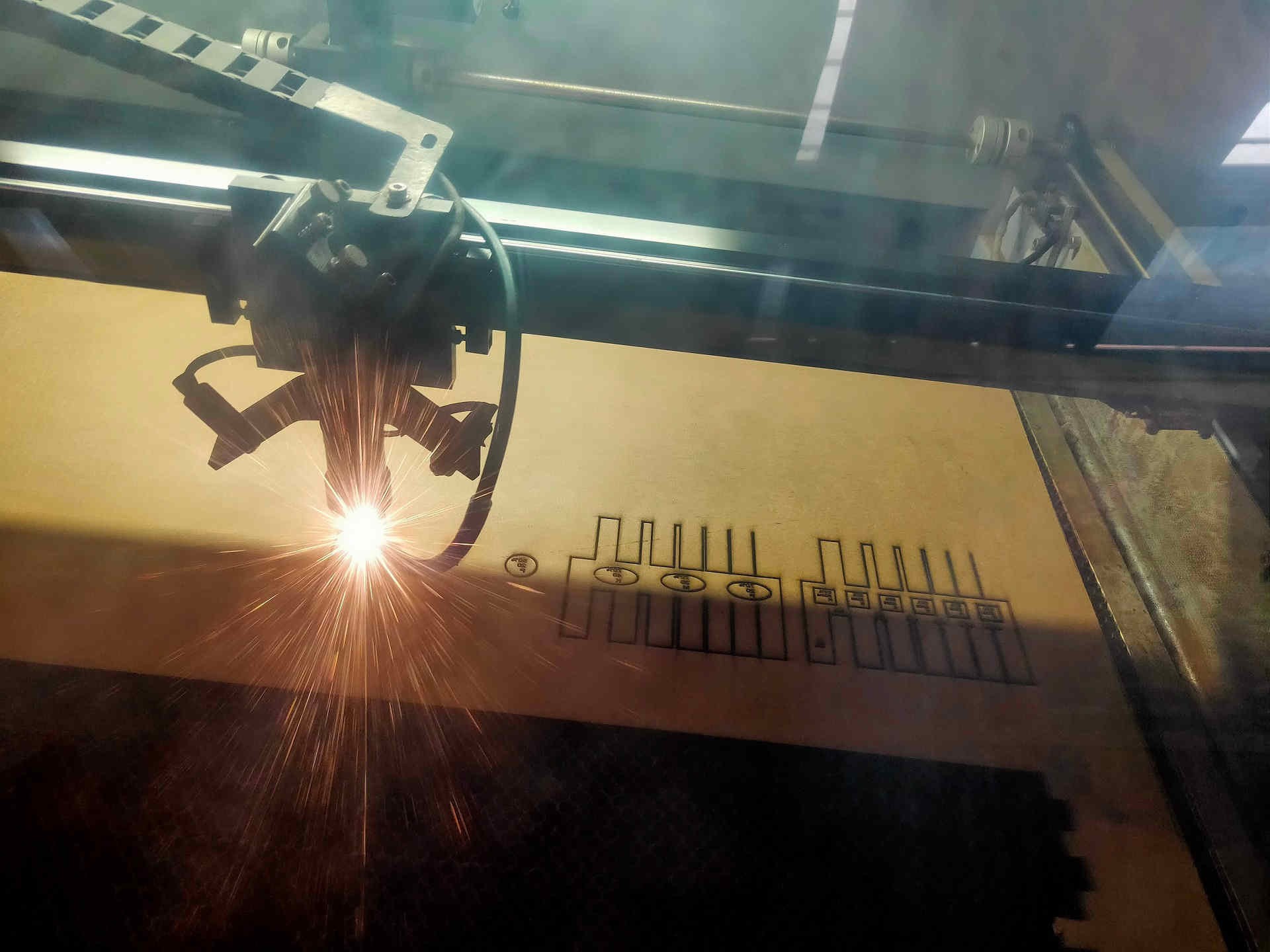
Laser Cut on Test MDF Ongoing
End Result of Laser Cut. Nothing Cut on Power and Speed from 50 to 70% and 20 to 40mm/s.
*The details of the Group Assignment could be found here.
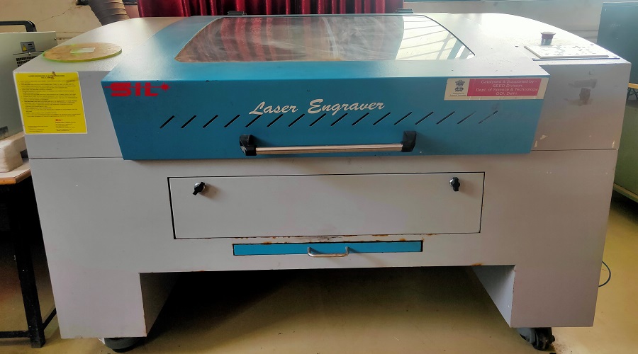
At Vigyan Ashram FabLab-0, we have SIL 1325-1318 Laser Engraver and Roland Cam 1 Vinyl Cutter. The details are discussed in the Individual assignment.
Individual Assignment:
Laser Cutter:
Types of Lasers:
CO2 (10.6 microns) - For Non-metallic cutting
Fiber (1 to 2 microns) - For Metallic cutting
Laser Concept and Working:
The laser cutter has a CO2 tube in the rear side. Due to the electric discharge, CO2 atoms get the energy and they are excited which in turn result in the emission of photons.
These excited photons having the same wavelength are channelized and focused on the mirrors which are diverted to the head of the beam which cuts the materials.
SIL 1325-1318 (Suresh Indu Laser):
SIL Laser Engraving - Cutting Machine is versatile & finds application in signage, indoor & outdoor advertisement, art & craft, gift, shoes, toys, garments, model cutting, papers & packaging, wood & MDF cutting industry, interior, decorators and many more.
Details of the Laser Cutter at Vigyan Ashram, Pabal:
| Particular | Description |
|---|---|
| Name: | SIL Laser Engraver (Suresh Indu Lasers) |
| Model No. | 1325-1318 |
| Engraving Speed: | 0-640000 mm/min |
| Cutting Speed: | 0-30000 mm/min |
| Laser Type: | CO2 DC Laser Glass Tube |
| Laser Power: | 80 Watt |
| Processing Area: | 900 x 600 mm |
| Power Supply: | AC 220V +/- 5%; 50 – 60 Hz |
| Formats Support: | AI, BMP, PLT, DXF, DST, CDR etc |
| For: | Non-metallic materials |
Features of the Laser Cutter Machine (SIL 1325-1318):
Top cutting precision and positional accuracy,
Improved edge quality and surface finish,
Strong repeatability,
Useful for materials not cut by traditional devices,
Drilling and engraving in addition to cutting,
Negligible workpiece degradation,
Cost-effectiveness,
Minimal thermal stress zone,
Cuts of complex shapes
Process of Starting the Laser Cutting Machine:
1. Check / Turn ON Mains (SIL Board)
2. Turn ON Isolation Transformer (Isolation Transformer)
3. Turn ON the Inverter (Press the 4th button till the connection is made between the I/p to O/p)
4. Turn ON the Cooler
5. Turn ON the Compressor
6. Switch ON the Main switch located in the left bottom of the machine
7. Turn/Rotate the Emergency Switch to the right slightly (Display will Turn On)
8. Turn ON the Lamp (Button located on the right bottom side of the machine.)
9. Set up the bed area
10. Turn ON the exhaust
11. Turn ON the Laser beam.
Terminologies related to Laser cutter:
Kerf:
The thickness of the laser is called as kerf. Due to its own thickness of the laser beam, laser cuts the material with grater/smaller dimensions. This may result in the change in the original dimensions. We have to calculate the kerf by calculating the difference in the original values assigned to a job compared to the resultant job. Generally, the material falls short of the desired dimensions. Very minute cuts may not be successful. {kerf= (X-axis kerf + Y-axis kerf)/2}
Eg. Given dimensions are 20 x 20 mm and the resultant dimensions of object after laser cutting are 19 x 19 mm then the kerf would be (1+1)/2 i.e. 0.10 mm
Focus:
The X and Y axes in the design are already assigned and set. We need to adjust the Z- axis i.e the depth or height of the laser beam according the material we are using and its thickness. If not set properly, the power and speed may not work properly and result in undesirable results.
Speed:
The speed at which the head of the laser beam moves over the material for engraving/scanning or cutting is called as the speed.
*Speed is inversely proportional to the Power.
If we want to cut, then the Speed should be less and the Power should be more and vice versa.
Power:
It is one of the most important factors to be always monitored and understood. More power may even burn a material or less power may result in not cutting a material.
There should be good combination of Speed and Power for getting the job done well.
While calculating kerf as a part of Group assignment, our cardboard caught fire due to high power of 70% and low speed 20 mm/sec.
Safety Factors:
Do Not Operate the laser unless all covers are in place and interlocks are working properly.
Do not look directly into the laser beam. Laser beam is the invisible high energy which can causes severe eye damage.
Use materials that are inflammable, non-explosive or will not produce any toxic by-products. Plastic/PVC material if used will melt.
Remove material from the cutting bed after it has cooled.
Do not leave a laser cutting operation unattended.
Always clean up residue, debris and flammable material in the laser cutter after use.
Always keep a properly maintained fire extinguisher nearby.
Do not use a laser cutter with a malfunctioning exhaust system or clogged air filter.
Caution:
1. While designing an object, always set the size in (millimetres) mm.
2. Shut down Laser beam at first after the laser cutting of a job is finished.
3. Don't leave ant material inside the laser cutter or on the bed area.
4. Don't work with the laser cutter with Open lid.
5. Refer the Manual before working.
6. Operate the laser cutter under supervision.
Individual Assignment:
Parametric Design in freeCAD using Spreadsheet
Use of RDWorks software to interface with the laser cutter (g code)
Use of Laser cutter
Parametric Design is a design where there is relationship between all the parameters / dimensions of an object. Change in one of the parameters of an object results in proportionate changes in other parameters/dimensions.
I have used freeCAD for parametric design to create a press fit job. There are various types of joints like press fit, snap fit, flexure, pinned, finger, snap wedge etc.
I have created a square with grooves on its four sides for press fit joint using freeCAD. The process of creating these squares is as-
1. Open freeCAD --> Create New document -->
Go to Start and select Spreadsheet workbench -->
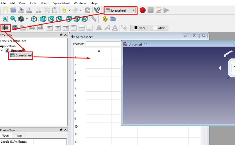
Click on the Spreadsheet to create New Spreadsheet -->
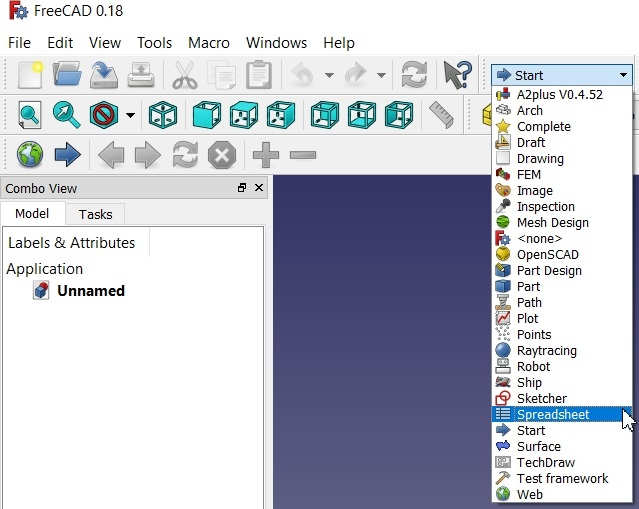 Go to Start and select Spreadsheet workbench | 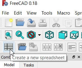 Click on the Spreadsheet to create New Spreadsheet |
|---|
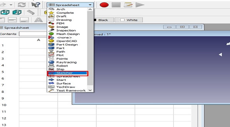
2. Again go to Start and select Sketcher workbench -->
Select the XY plane for creating new design -->
3. Go to the Windows Menu and select Tile mode to simultaneously view the Spreadsheet and the Sketch workbench -->
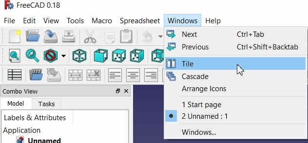
Click on Tile Menu to view Sketch and Spreadsheet simultaneously
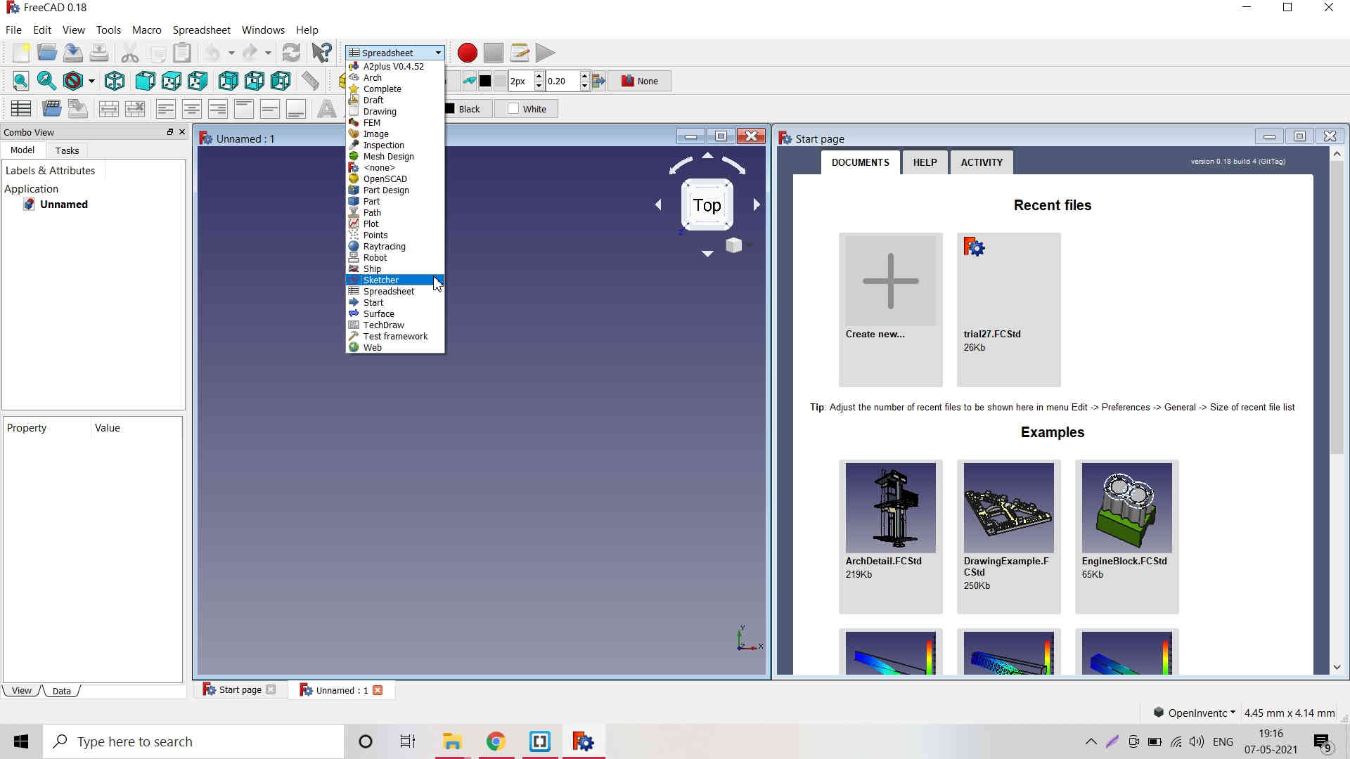
Again go to Start and select Sketcher workbench; Switch to Sketcher Workbench
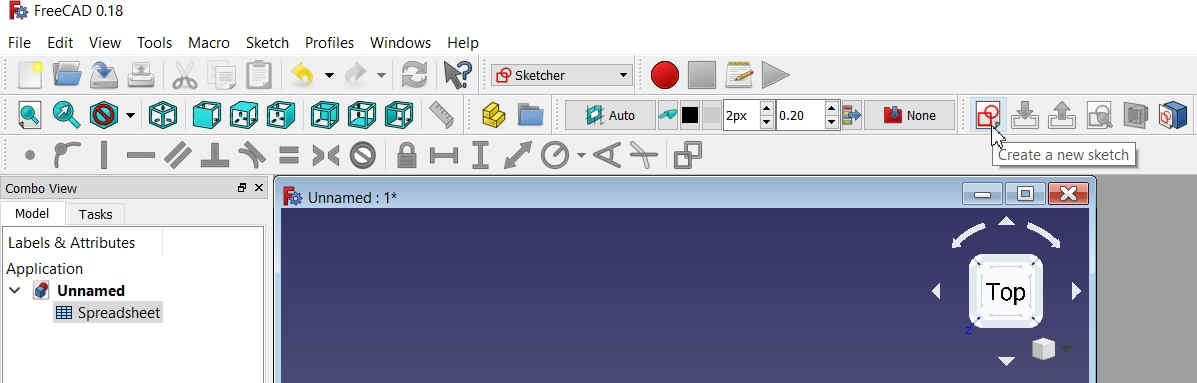
Click on Create New Sketch
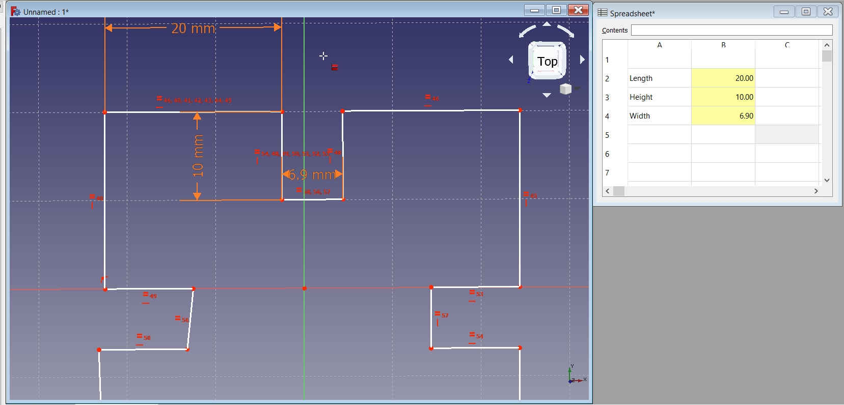
4. Add Parameters in the Spreadsheet like Length, Breadth/Width, Height to be assigned to the image/object. -->
Eg. Length 10 mm; Right Click on the value 10 mm cell to select the Properties and then select Alias name as L.
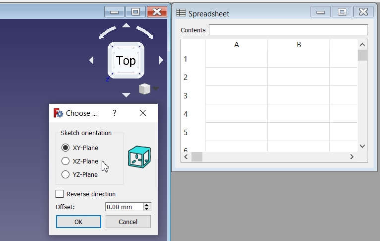 Select the PLane on which you want to draw/design | 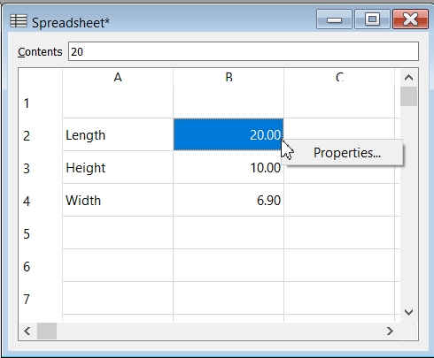 Add Parameters in the Spreadsheet like Length, Breadth/Width, Height to be assigned to the image/object. |
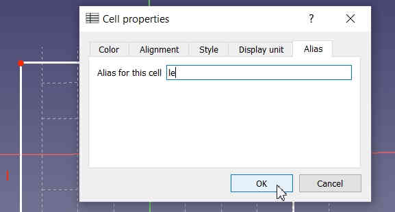 Eg. Length 10 mm; Right Click on the value 10 mm cell to select the Properties and then select Alias name as Le. | 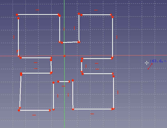 |
|---|
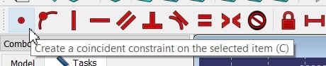
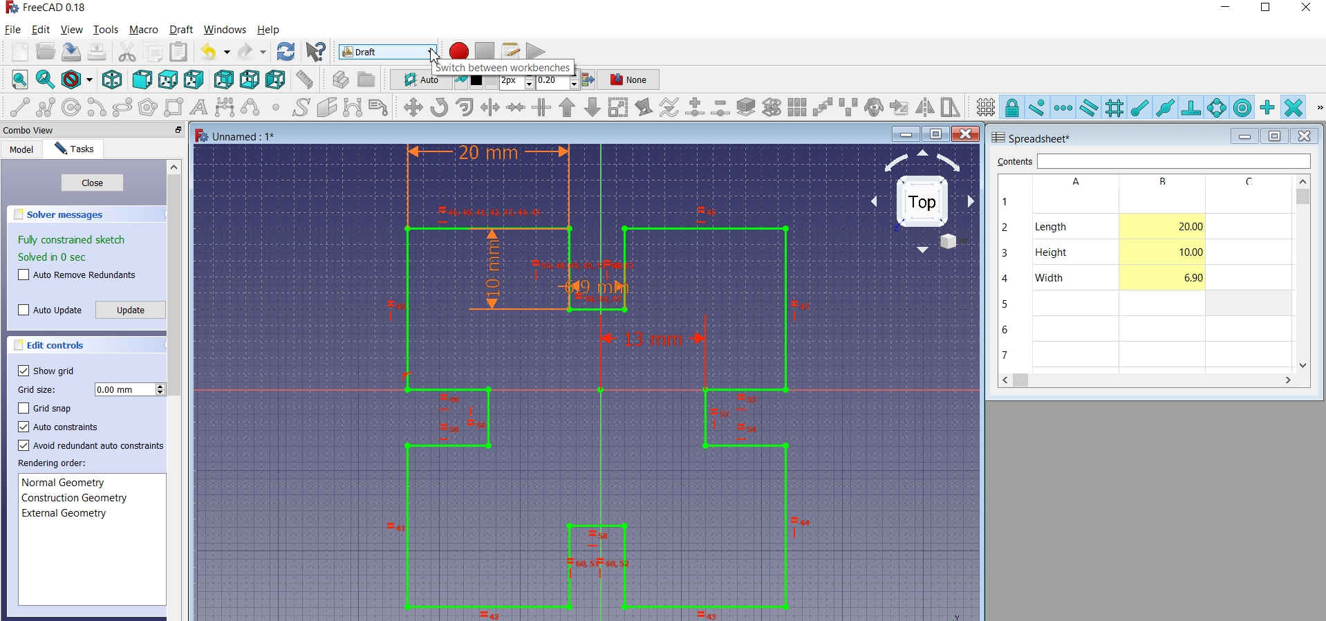
5. For Drawing Shape in Sketcher workbench and adding constraints -->
I drew a Square and fixed its position with respect to the X and Y axes by giving constraints to define its position from the origin. -->
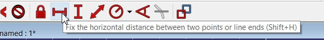
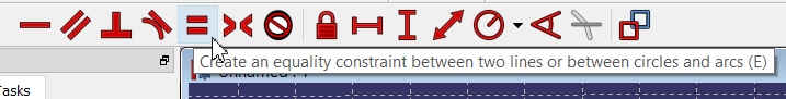
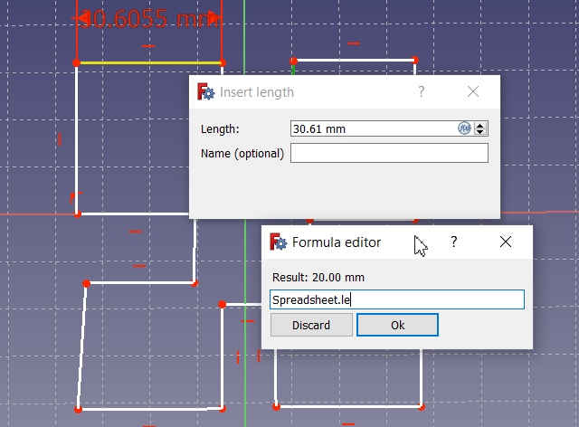
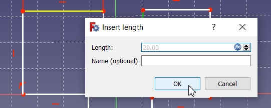
Then I applied constraints to the sides of the square by defining its size in mm. For this, I used horizontal and vertical constraint lines and clicked on the circle which opens a dialogue box to feed the value. There, I have selected the Spreadsheet.Le to assign the constraint. -->
After connecting the lines and attaching them to the main object, I trimmed the line and grooves were created in the square.
 |  |
*I tried to apply fillet to the edges but the dimensions were changing so I restricted myself and left the grooves without fillets.
After completely applying constraints to the image, I tried to change the values of the image in spreadsheet to see its reflection in the image. It worked. -->
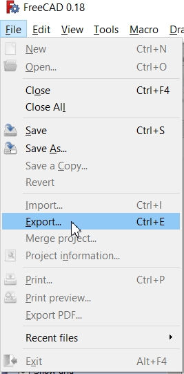
6. I saved the file in the standard freeCAD extension.
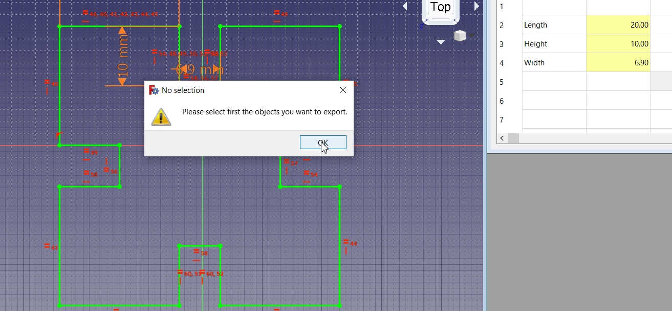
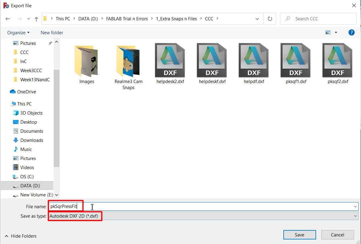
7. Then I went to the Drafts menu and selected file menu to export the file. I have selected Autodesk DXF 2D from the dropdown and exported the file in .dxf file extension format. -->
8. A dialogue box popped up which asked me to connect with the internet. -->
*Autodesk is not opensource software so if we are saving the freeCAD file in .dxf format, it needs a extension to convert the file and we need to download it. -->
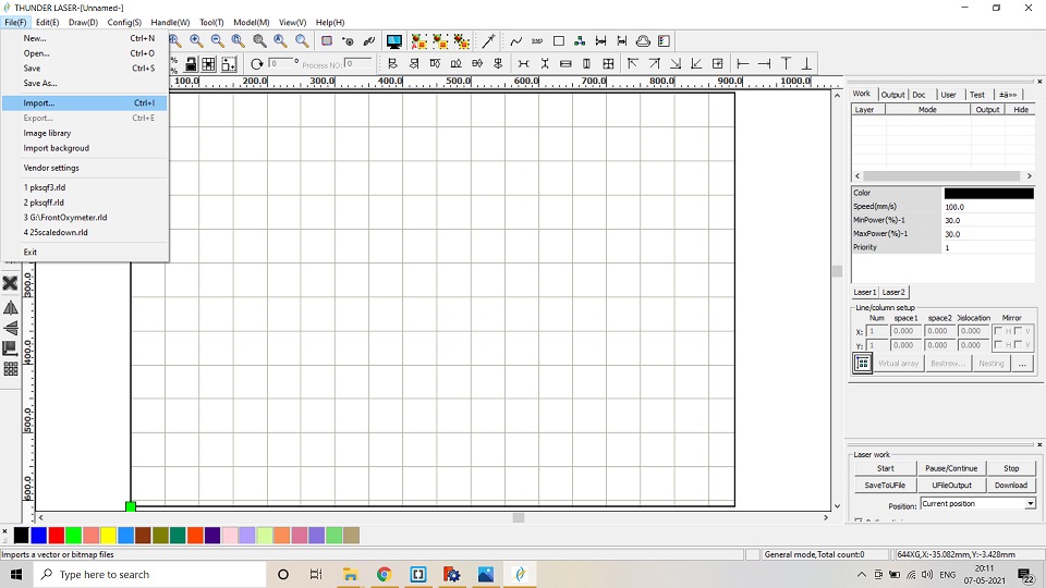
9. After saving the file in the .dxf format, I imported the file in the RD works Software which acts as a liaison between the design and laser cutting m/c. -->
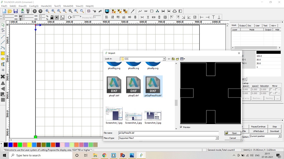
10. In RD Works software, I resized and copied the image to replicate and make multiple shapes for laser cutting. -->
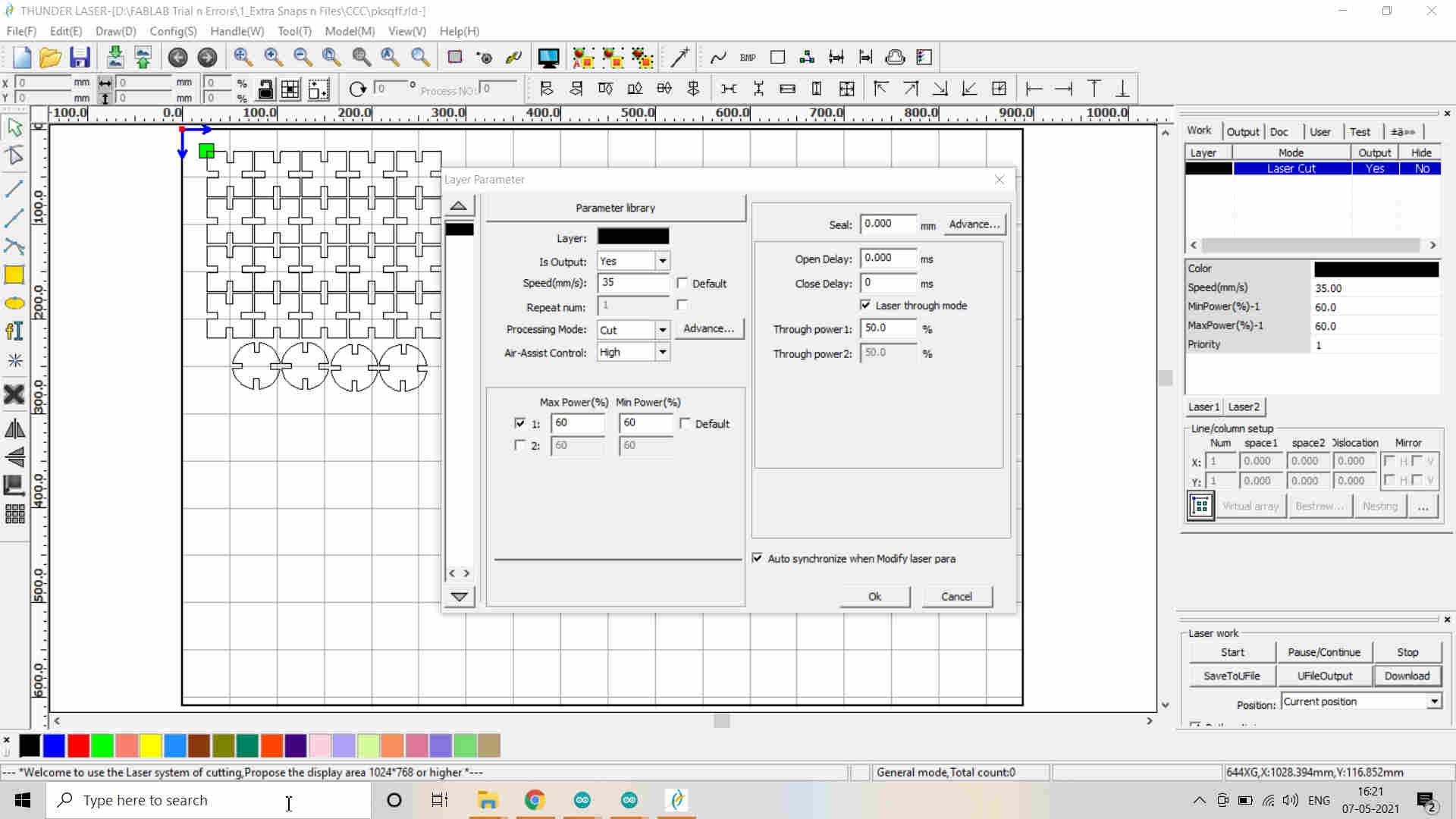
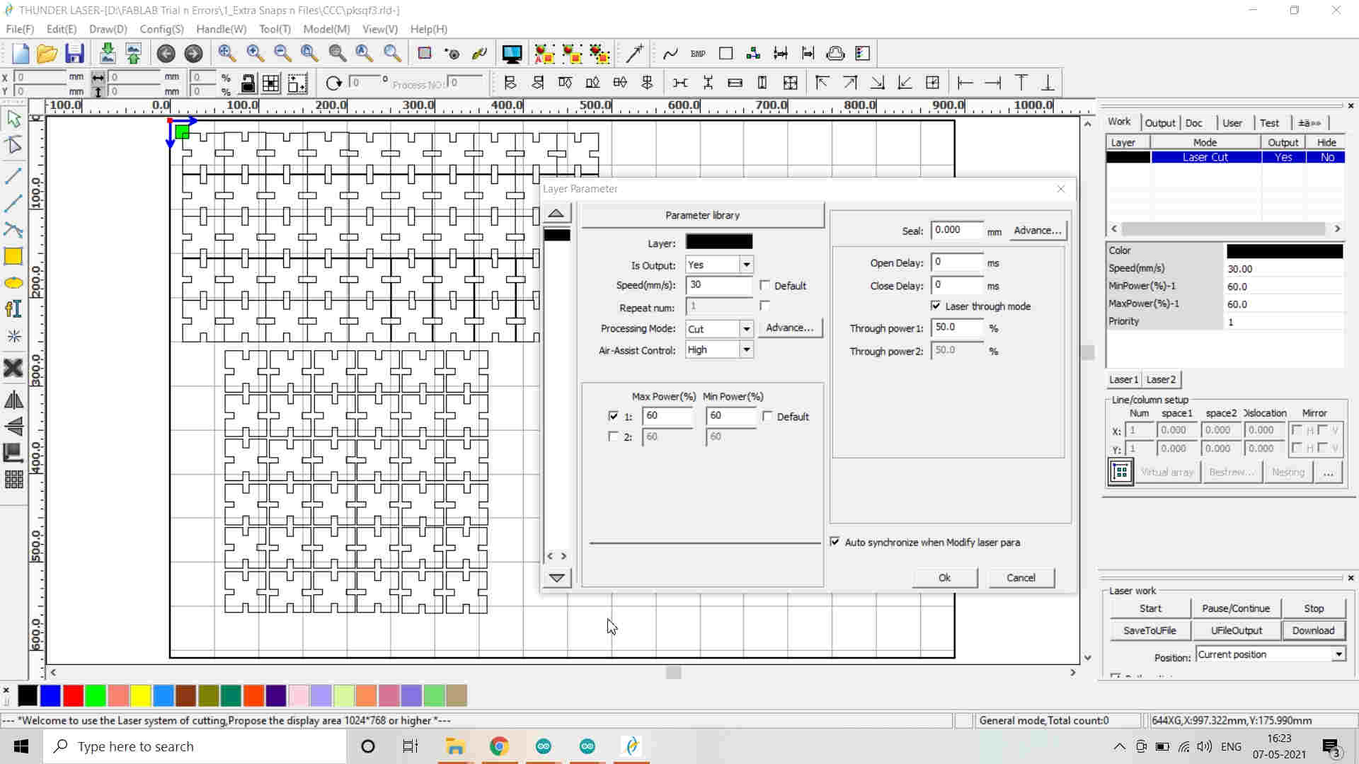
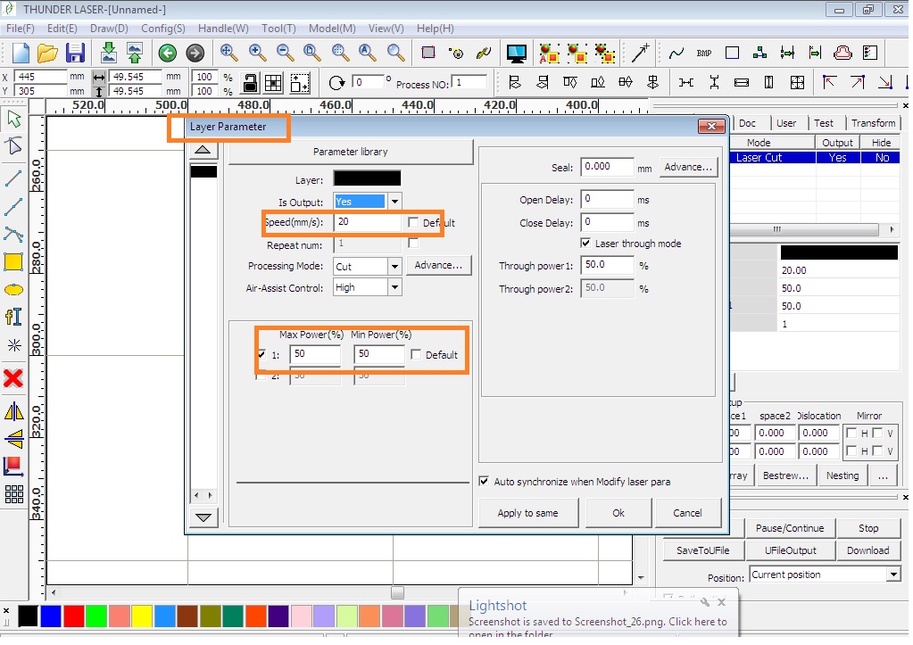
11. The image needs to be given proper color codes which I selected from the tray at the bottom and assigned the function to Cut or Engrave/Scan the image by selecting appropriate Power and Speed also called as the Layer parameters. (Default color code is Black.) -->
*Note that the kerf of 0.20 mm. (already calculated in the group assignment) is to be added to the design before replicating it in numbers and also the Power and Speed is defined (P=65% and S=30 mm/sec.) -->
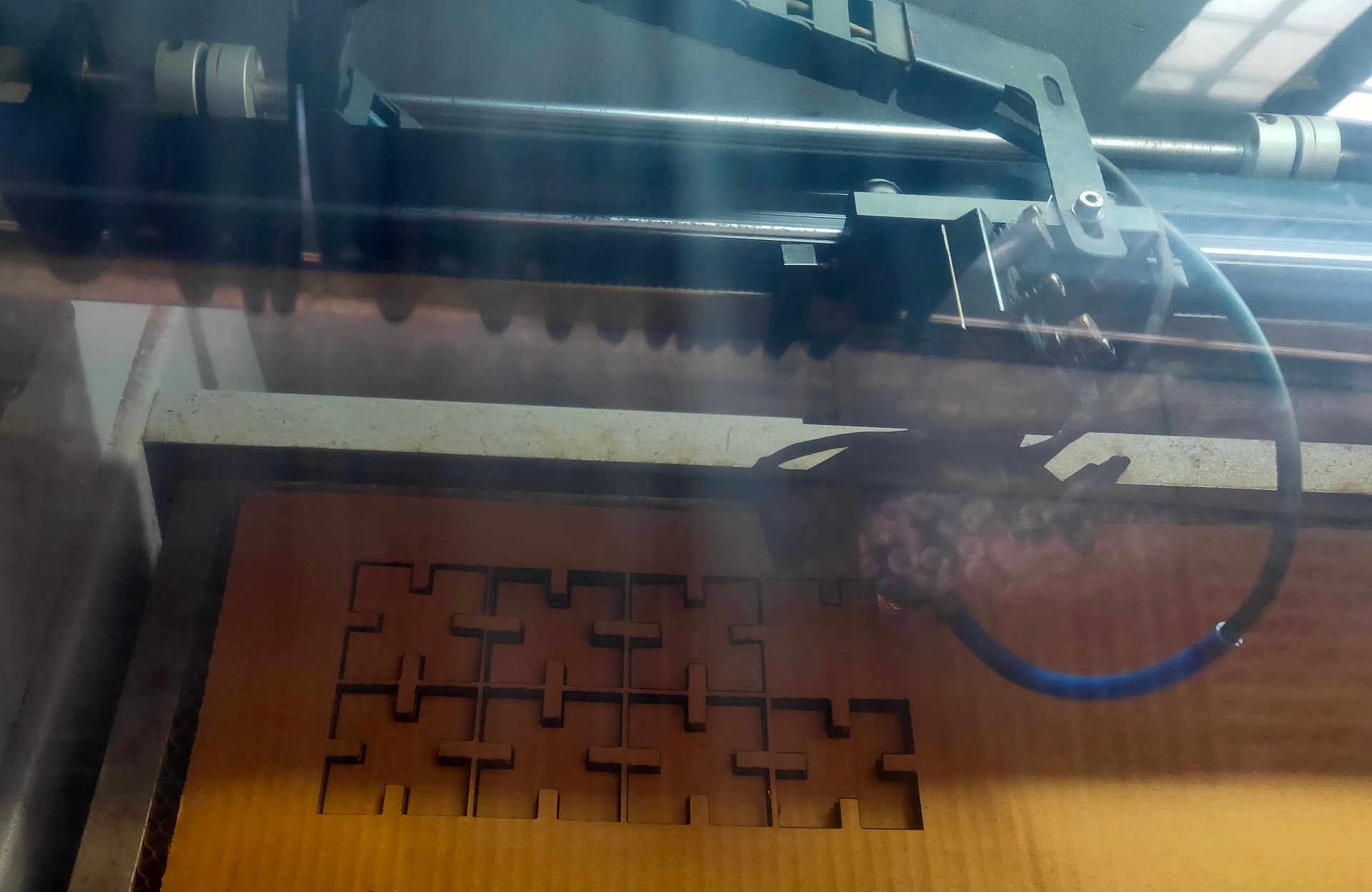
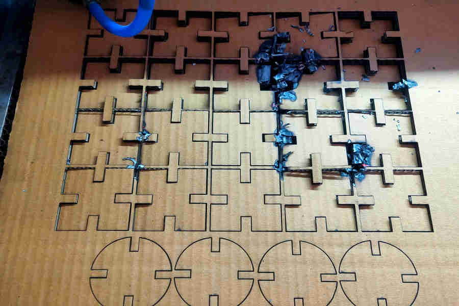 |  |
The Cardboard was burnt during the Laser Cutting. I immediately stopped the Laser Cutter by cancelling. This might be because of closely placed squares or because of more Power and Lesser Speed. As the Squares were not attached to each other and very closely placed, this made the Laser Cutter to take two passes and that why may be the Cardboard have burnt. I conveyed this to other friends and they changed their Laser Cut settings accordingly. I increased the Speed to 30 mm/sec and Reduced the Laser Power to 65% afterwards. These settings may vary according to the Height of the CardBoard material as well.
12. Note:
Arrange the design for optimum utilization of material.
While using USB drive, save the file in .rld format and .dxf format while using the Laptop.
Shorten the length of the name of the file.
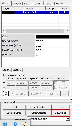
13. Click on the download menu to download the file in the laser cutter.
14. Hands on Laser Cutter:
After switching the Laser cutter ON according to the process mentioned earlier,
i. Place the material to be cut on the bed area. -->
ii. Set the origin of the Head of the beam and click OK. -->
iii. X and Y axes are already defined in the image. For setting the Z axis, use the bed leveller upon the material.
iv. Adjust the height of the head using the left or right direction arrows on the Display panel of the machine. The head should just touch the leveller.
v. Press Escape button after completion of every operation. Select the file from the library and push enter button.
vi. Check the frame of the design and adjust the material if required.
vii. Close the lid of the laser cutter.
viii. Start the Laser cutting.
ix. After cutting is completed, Turn OFF the laser beam.
x. Wait for minute to allow the exhaust of fumes and gases.
xi. Push the images on the material to see if they are properly cut. If not, then apply the double pass and start the laser cutter again.
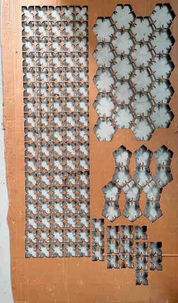
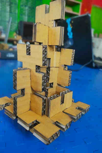
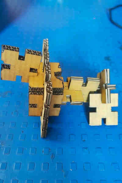
15. Collect the laser cut material and assemble the parts to create various shapes.
Pressfit Assembly Images:
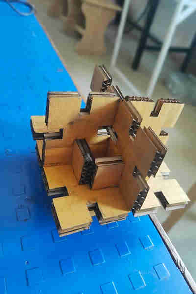
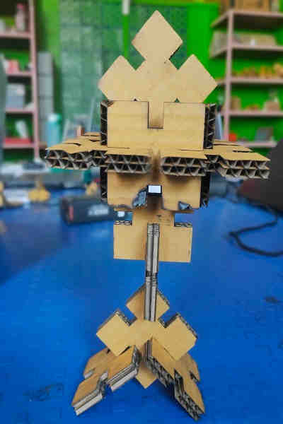
Summary (Laser Cutting):
I learnt the DO’s and DON’T’S to operate the SIL laser engraving machine and create various shapes for press fit assembly. I also learnt to export files in machine compatible format.
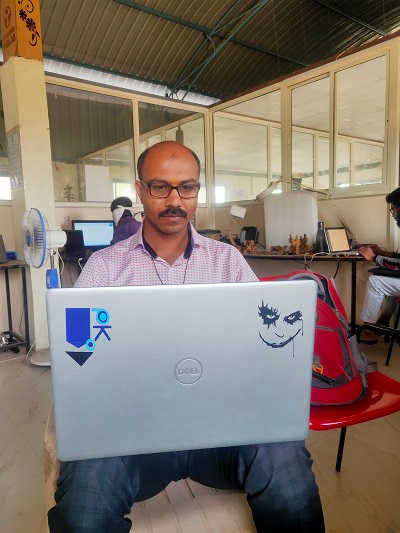
Vinyl Cutting:
Our FabLab-0 at Vigyan Ashram, Pabal has Roland Camm-1000.
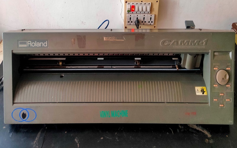
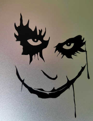
It is used for cutting the vinyl, even plastic film, copper film for electronics PCB design. We had to cut the logo or any design on this machine. This machine tempts you to be creative and adds aesthetics to the product.
I have thought of printing a logo already prepared in CAD week but it could not be printed because of its layers and bitmapping failure.
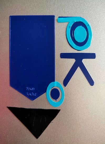
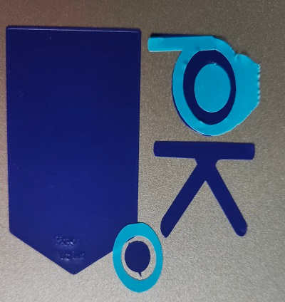
I then designed a logo in Inkscape.
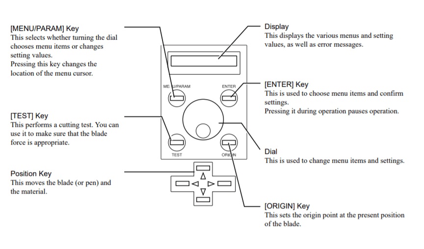
Roland Camm-1 Vinyl cutter Operational Process:
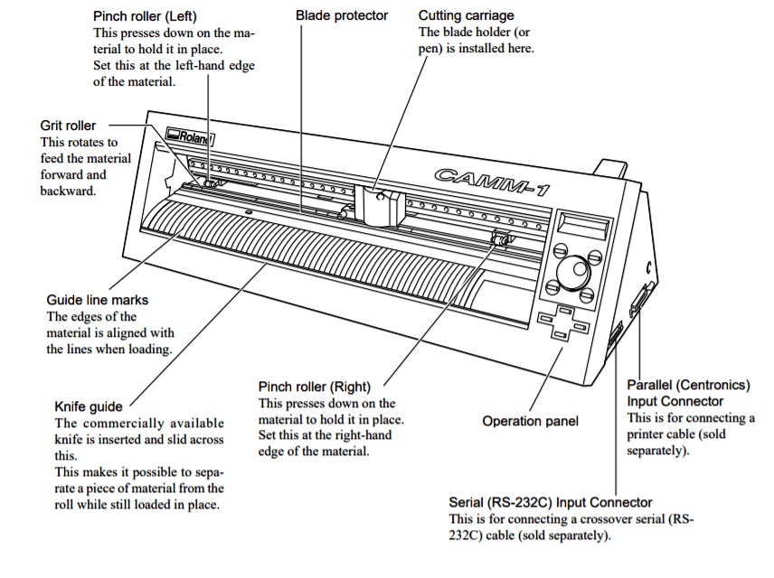
1. Switch ON the mains. -->
2. Set the parameters for the image to be cut in the mods on desktop PC.
3. Set the rolls by placing them under the white markings. (There are 3 markings in the machine. This defines the cut area.)
4. Allow the sensor to sense the material.
5. Set the origin of the head of vinyl cutter.
6. Select the appropriate settings from Roll, Edge or Sheet for the detection by the m/c for determining the width of the vinyl material.
7. To avoid Weeding (Picking/Cutting what is not needed and leaving that is needed), adjust the blade properly. Be cautious while dealing with the blade as it is very sharp and placed at 45-degree angle.
8. Load the Vinyl paper or copper film.
9. Lift the clamp situated at the back side of the machine. This clamp holds the material in its place and allows proper cutting.
Vinyl Cutting Order Flow:
1. Boot the Desktop terminal using Ubuntu OS.
2. Open Terminal and use commands
3. cd Documents to change directory. --> mods --> bash mods
4. Again Open New Terminal and use commands
5. Cd Documents --> http – server
6. This will open a Window in Google Browser.
7. Right Click in the Window
8. Four options will be displayed like Modules, Programs, Edit, Options etc.
9. Select Programs --> Select Open --> Select Roland Camm-1 Cut option -->Go through the each step of the Module --> Select the
Photo/Image to be used for vinyl cutting
10. Check the format of the image (.svg or .png)
11. Check the Tool Path
12. Open the Socket by inserting (ttyUSB0)
13. Calculate the path
14. Open the Socket and
15. Send the File for vinyl cutting.
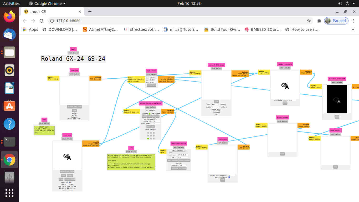
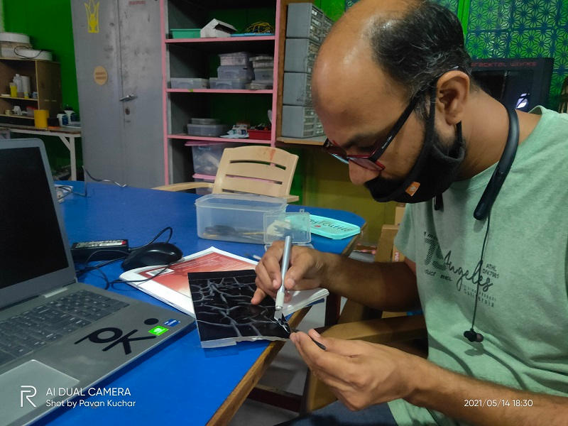
Image Gallery:
Original Files:
Here, I have included the Trial and Final Design Files for reference. I have designed the Parametric Square for PressFit Assembly in FreeCAD (pksqf.FCStd files). I have also designed the Mobile Stand, HelpDesk (A School Bag and Desk) for Poor Children distributed at Rs.10 in Maharashtra by NGO named "Aarambh". But I couldnt finish it. I also tried my hands on designing Wrench Tool. But, the design file of Square and its Slicing file (GCODE) (pksqff.RLD files) can be referred as Original File for this Assignment.
It also contains the Design Files of my Logo (vcpktrial.svg) for Vinyl Cutting which are saved in .SVG format.