Objective:
- To Model (raster, vector, 2D, 3D, render, animate, simulate, ...) a possible final project,
compress your images and videos, and post it on your class page
Learning Outcomes:
Evaluate and Select 2D and 3D softwares
Demonstrate and describe processes used in modelling with 2D and 3D software
Checklist:
1. Modelled experimental objects/part of a possible project in 2D and 3D software
2. Show how you did it with words/images/screenshots
3. Included your original design
Opening Quotes:
"FORM doesnot necessarily follow function...”
“Limitations make the Creative mind Inventive”
“Designs are an Expression of Values”
“Content preceeds Design: Design in the absence of Content is Decoration”
After the lecture by Neil on CAD, A lecture on Solid Works was organized where we were familiarized with various features and the dashboard commands. I tried to draw Interlocking brick. After the lecture by Neil on CAD, A lecture on Solid Works was organized where we were familiarized with various features and the dashboard commands. I tried to draw Interlocking brick. I used to draw on page but never designed anything using a software. Computer Graphics can be created as raster or vector images.
Raster:
The images made up of pixels (cells) organized in rows and columns (grid) which contain information and collectively form a picture.
They are bitmap images.
The images blur after zooming in to a certain limit. We can see the pixels in a grid. After zooming out, the image is smooth and clear.
Raster images are defined and displayed at specific resolution. The resolution is measured in dpi (dots per inch-1920 x 1080)
Common raster formats include GIF, JPEG, TIFF, PCX and BMP
Software’s used for 2D raster images are GIMP, Photoshop, BIMP, ImageMagick etc.
I usually use Paint for making diagrams. I have used GIMP and BIMP for image size reduction, but I don't know how to effectively use GIMP for making diagrams.
Earlier, the image size used to increase as I was not able to define the format to which the image is to be exported. It used to save in the PNG format.
We had GIMP tutorial from Pooja Jadhav where she introduced us to various functionalities of GIMP. I then tried to explore GIMP.
About Raster 2D Design using GIMP:
I had already downloaded GIMP as we were told to compress the size of our images before uploading to our website. But, as I mentioned earlier, I was not exporting the images to JPEG format, nor setting the pixel size, I had resultant images of bigger size.
Then I referred Gimp Tutorial
After following the steps mentioned, I was able to reduce the size of the images.
| Application | Image Size in MB | Image Resolution |
|---|---|---|
| Original | 3.90MB | 3456 x 4608 |
| Paint | 1.78 MB | 2465 x 1953 |
| GIMP | 314 Kb | 2465 x 1953 |
For Image processing, I referred Gimp Tutorial
Before
After
About Raster 2D Design using BIMP (a GIMP plugin/extension): Then, I tried using BIMP for batch resizing of images: Mistakes that I made were-
1. Dimensions:a. Out of the four options, I had to select whether to resize, fix or restrict height and width – Select desired option
b. Select the image size as per the dimensions used in the template of website that you have used or else the images may not fit in the position and disturb the alignment of the website. Due to this, I had to change 2 website templates.
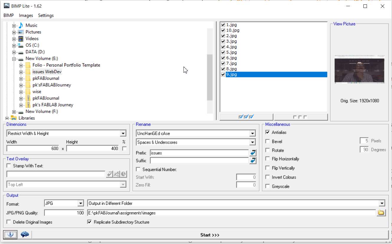
2. Output Format:
a. Select proper format from JPEG, PNG, TIFF, GIF, TGA, PCX or Don’t Change
b. Select the output folder, it is advisable to make two folders for image processing. One folder will be of Original images and the other one may be of processed images. If required, you may even opt to create third folder for images to be uploaded on website.
c. One major mistake that I made was to select the option of deleting the original images. I had to again take screenshots and process images for the assignment. 3. Rename: To differentiate, you may choose to rename the resultant processed image as Uppercase or Toggle case or Title case. If you choose, Unchanged case, it may be difficult for you to differentiate between original and processed images. You may also choose to prefix or suffix the resultant files. 4. Select or Deselect the images to be processed (size reduction).
What is Vector in graphics? Few Examples.
Vector graphics are based on mathematical formulas that define geometric primitives such as polygons, lines, curves, circles and rectangles.
Inherently, vector-based graphics are more malleable than raster images — thus, they are much more versatile, flexible and easy to use. The most obvious advantage of vector images over raster graphics is that vector images are quickly and perfectly scalable. There is no upper or lower limit for sizing vector images.
Vctor images are not resolution-dependent. Vector images have no fixed intrinsic resolution, rather they display at the resolution capability of whatever output device (monitor, printer) is rendering them.
Common vector formats include AI, EPS, SVG, and sometimes PDF.
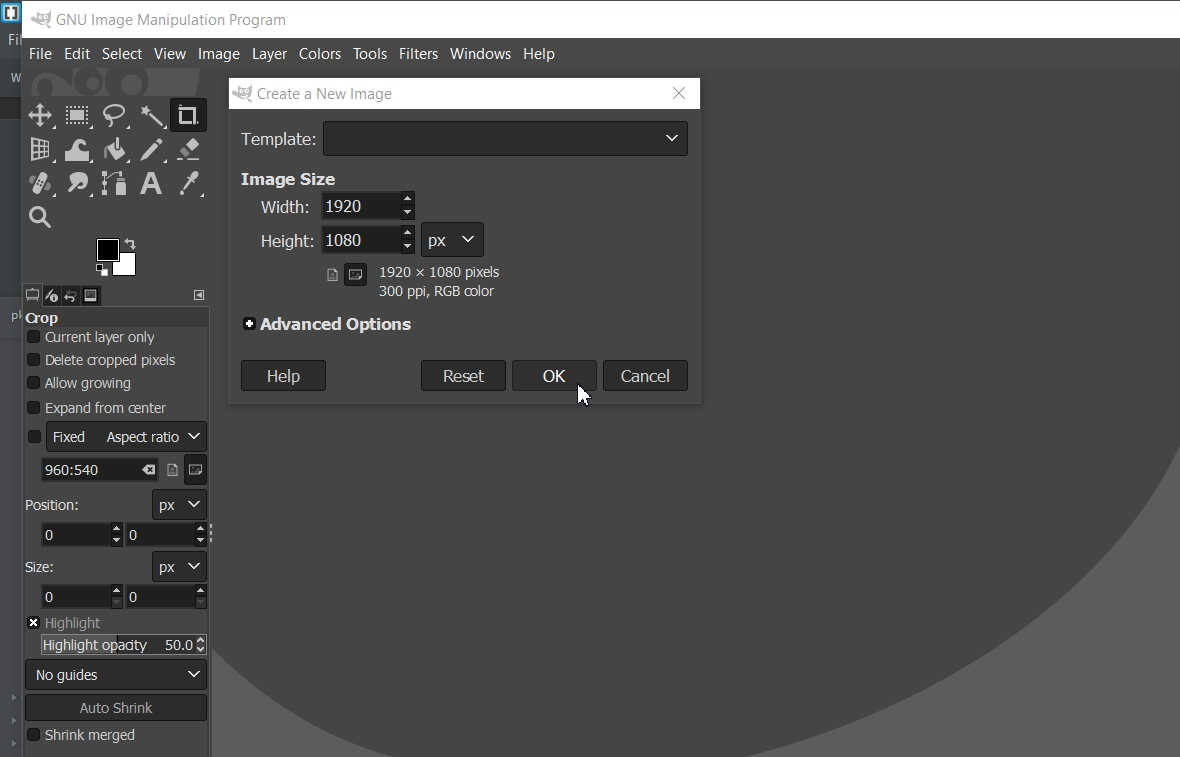
After Opening GIMP, define the Size of the Image
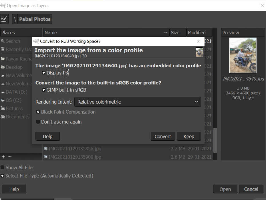
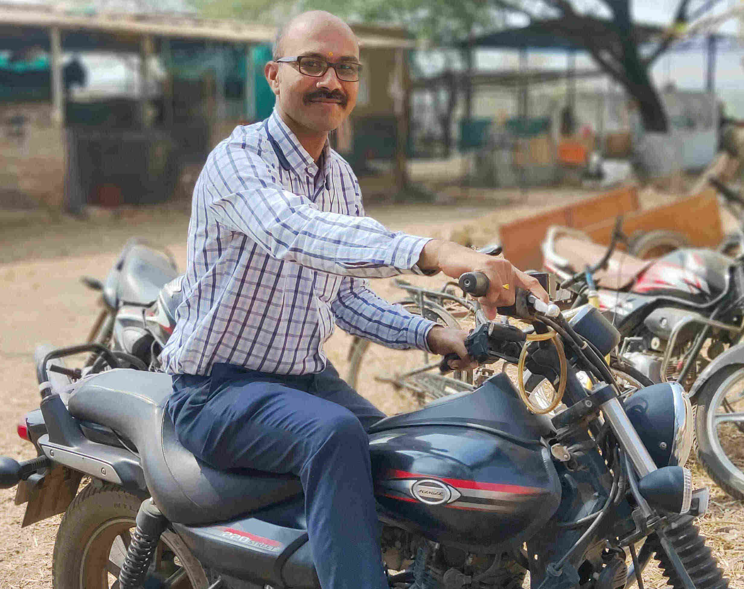
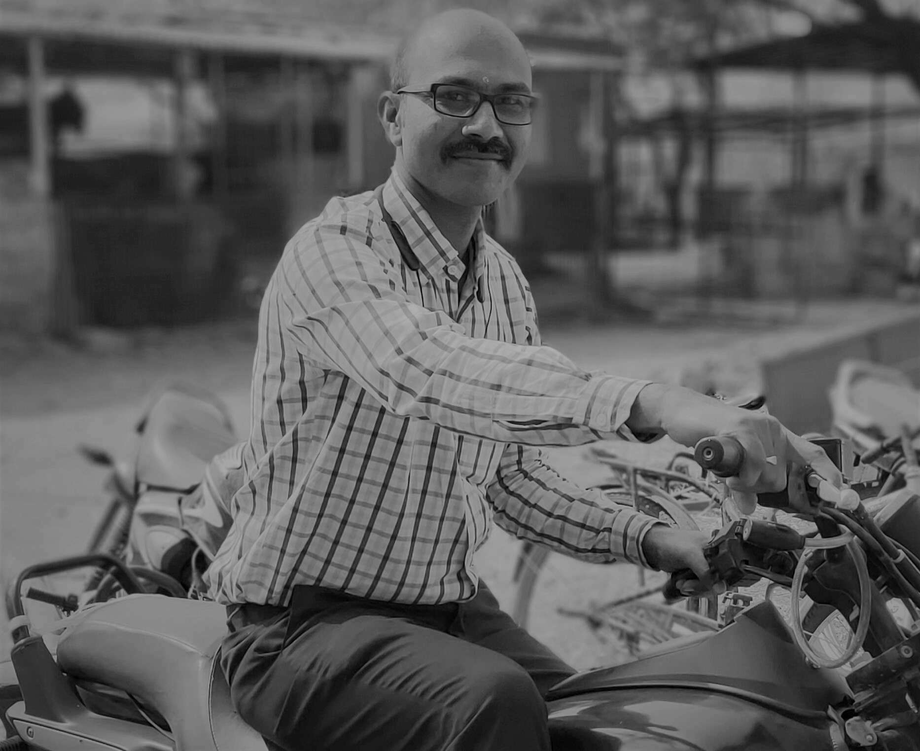
Import the Image to be Manipulated and Convert it to either Colorimetric or GrayScale or Relative as per the need. I have selected GrayScale
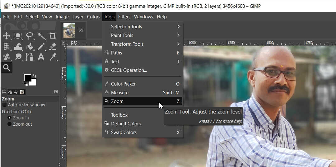
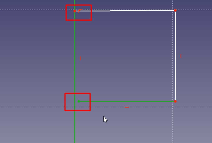
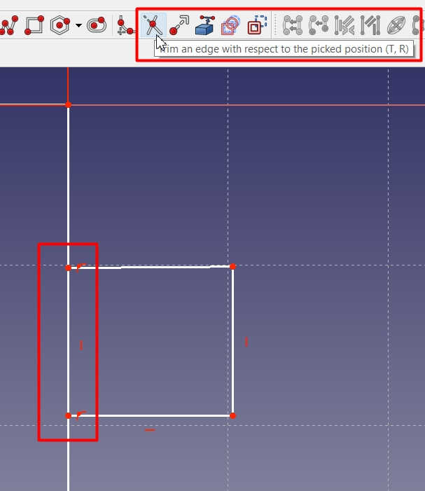
Tried Zooming In and Fit to selected Sketch
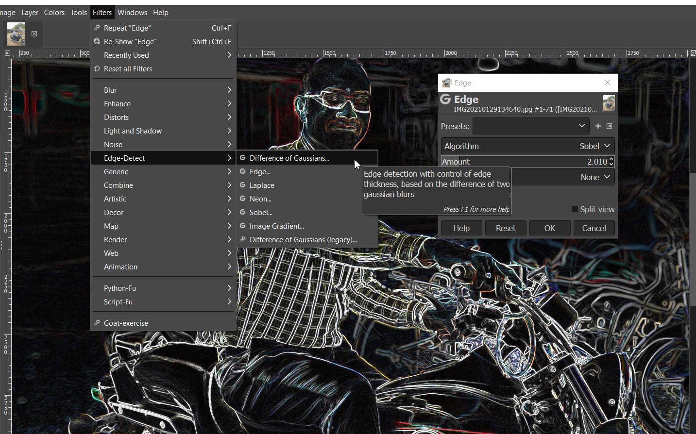
Tried the Edge option to Transform
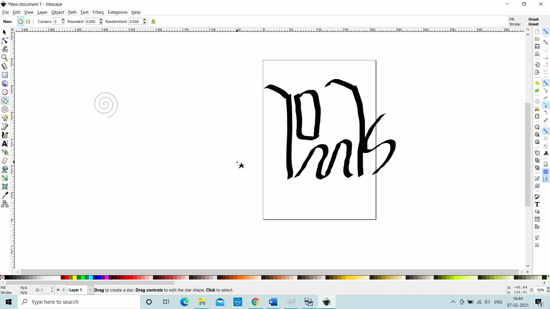
Inkscape: 2D Vector Design Software About 2D Vector: Inkscape I created the logo of my name using Inkscape. Mohit Ahuja (fellow Fab Academian) helped me to recreated the design that I thought of. Later on I went through Inkscape Tutorial for exploring it on my own.
Logo made for my Name

Selected the Pen; increased its Size and then drew it.
Before
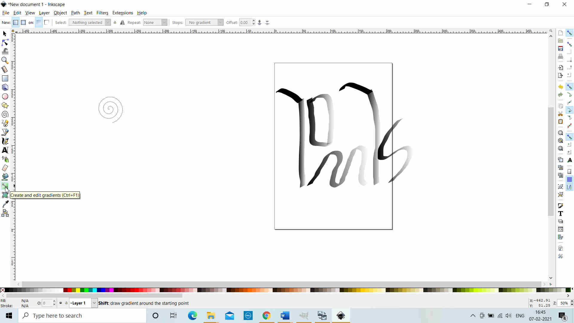
After
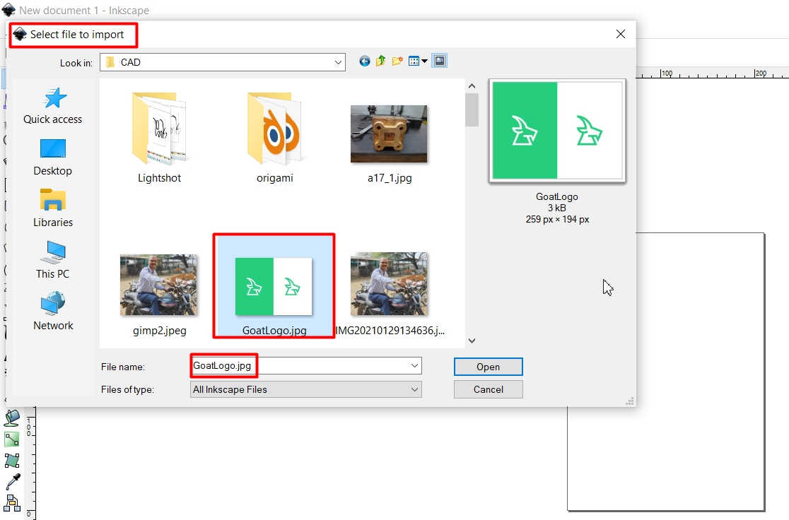
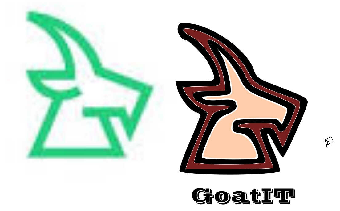
Imported the GoatIT Logo in InkScape for Editing as the file was in .JPEG format and the files in .SVG format can be Opened in InkScape
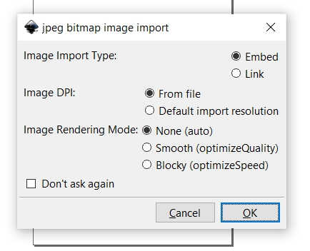
Message Pop Up after Importing the Image. I selected the Default options
Imported Image on the InkScape Workplane.
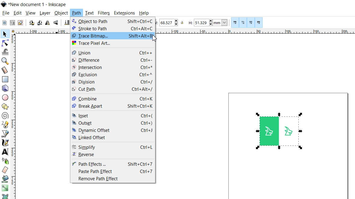
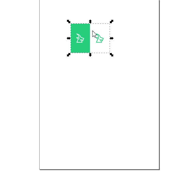
Trace Bitmap the Image to convert it to Vector and manipulate the Edges
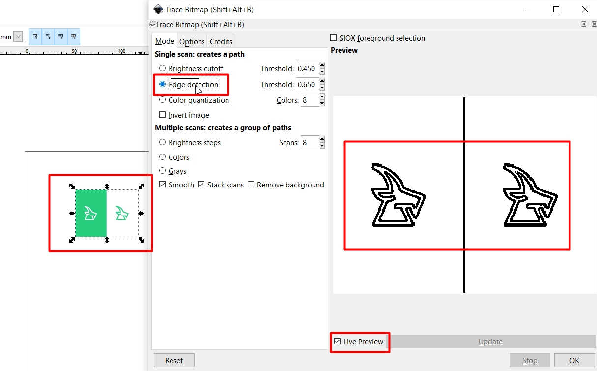
Selected the Edge Detection Option out of the Three as it looked better
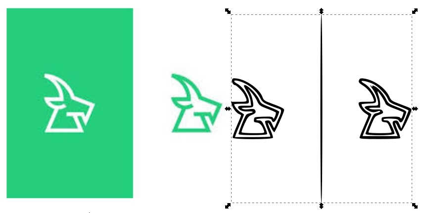
Original Image and the Trace Bitmap Image side by side
Filled the Colors and added the Text
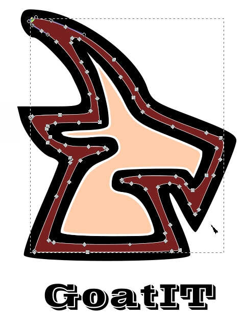
Selected the Vectors to manipulate a bit
Simply put, Painting can be done with the pixels and
Drawing can be done with the Vectors
3D Design:
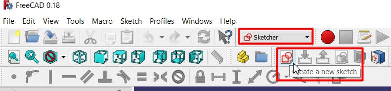
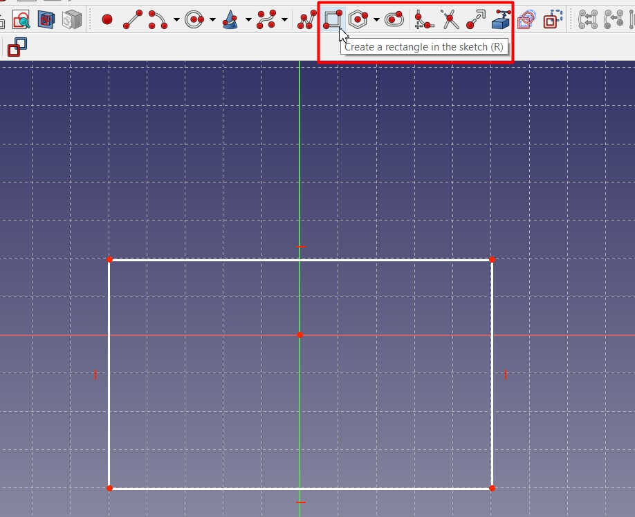
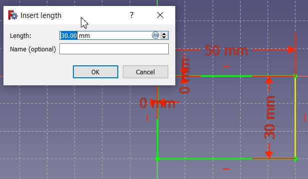
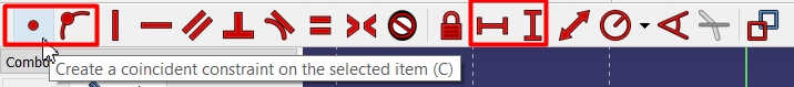
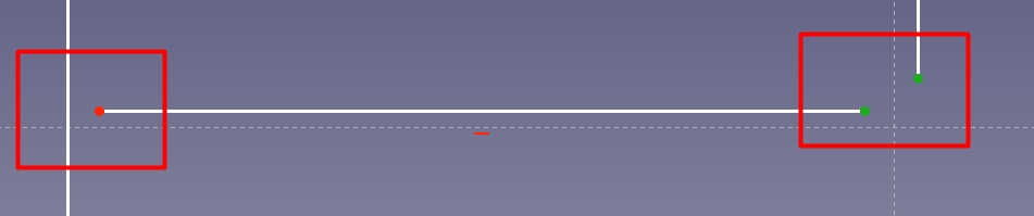
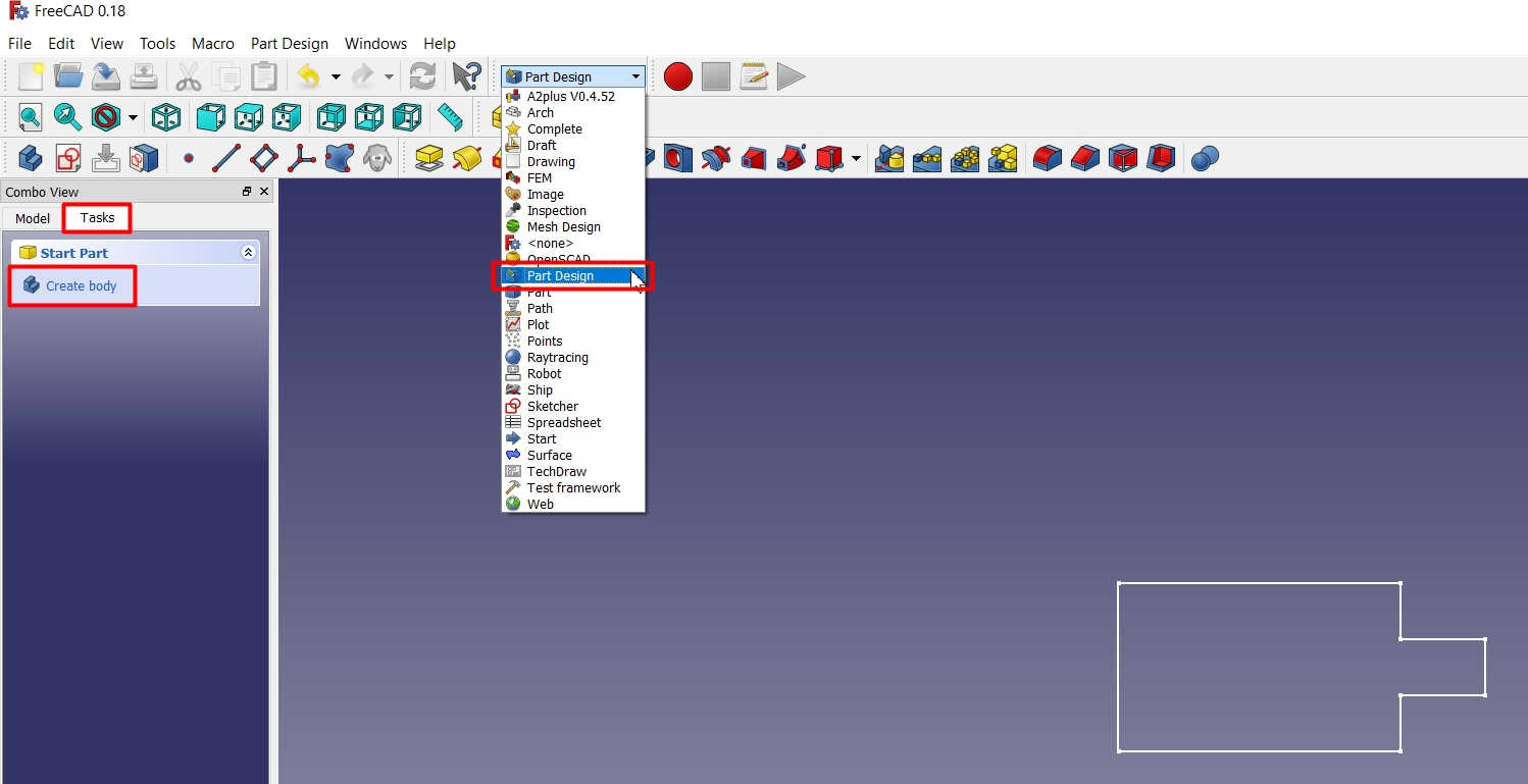
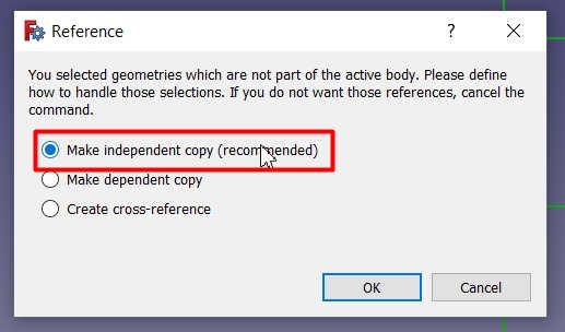
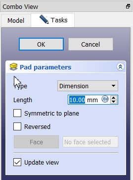
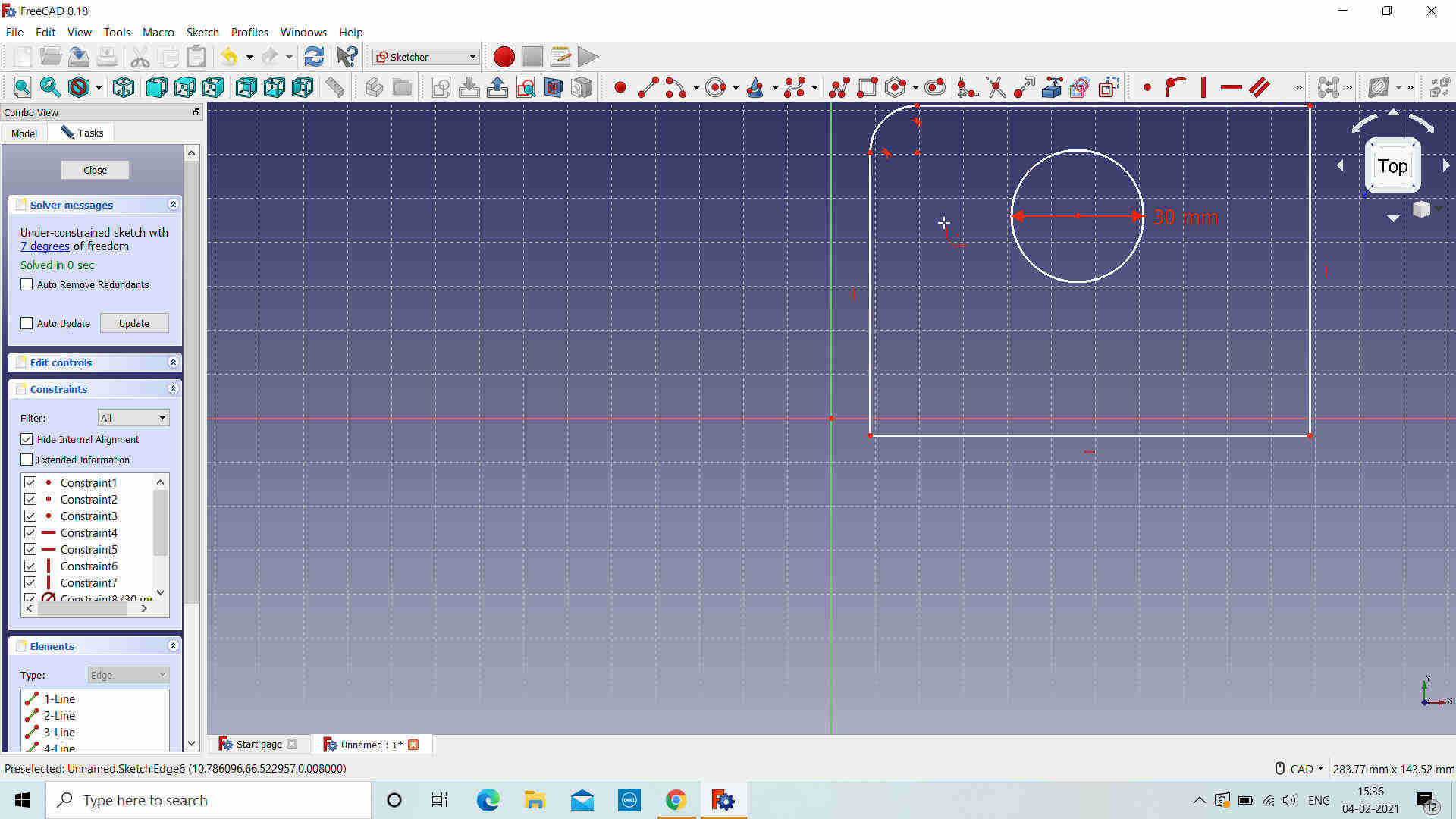
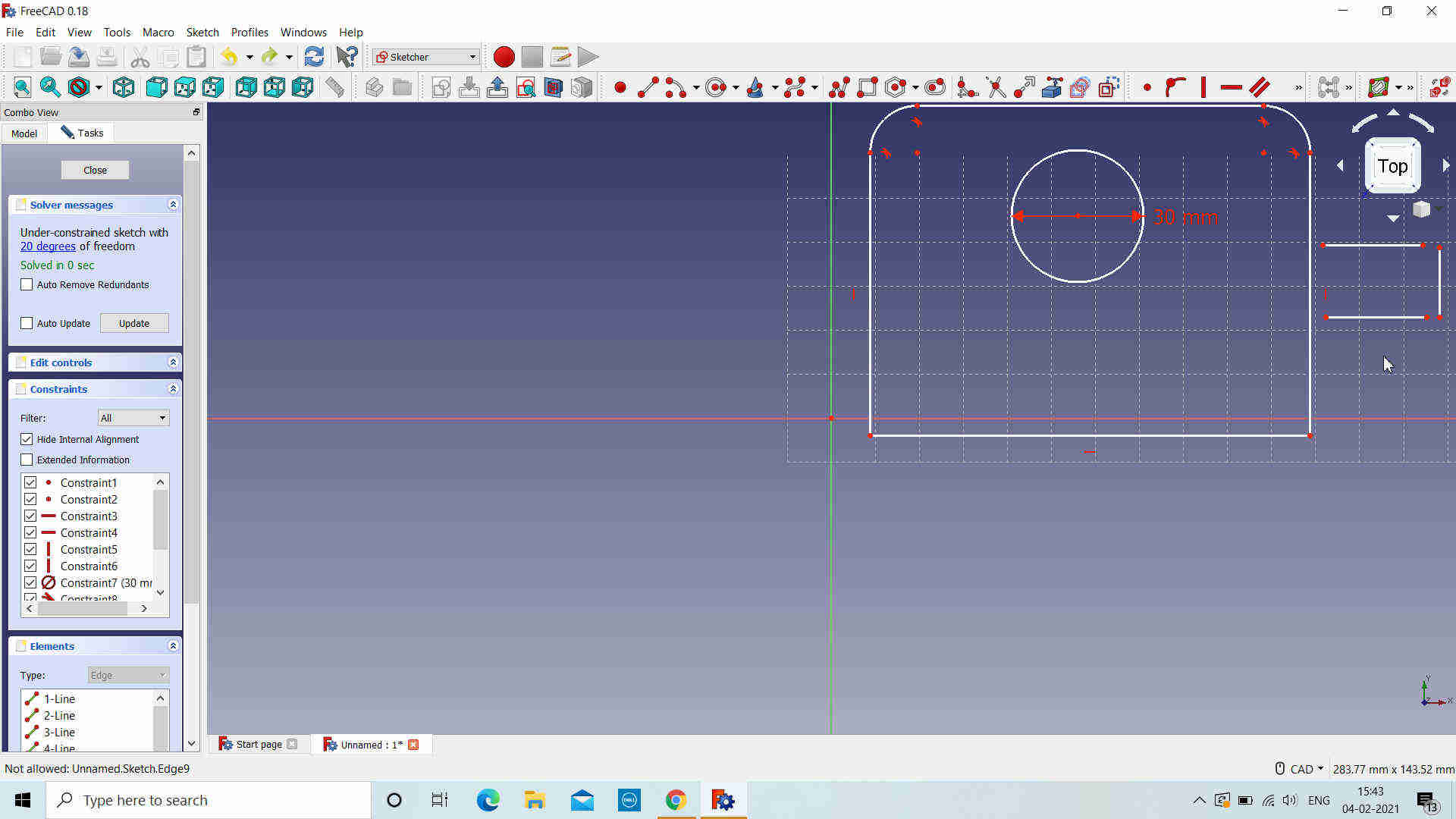
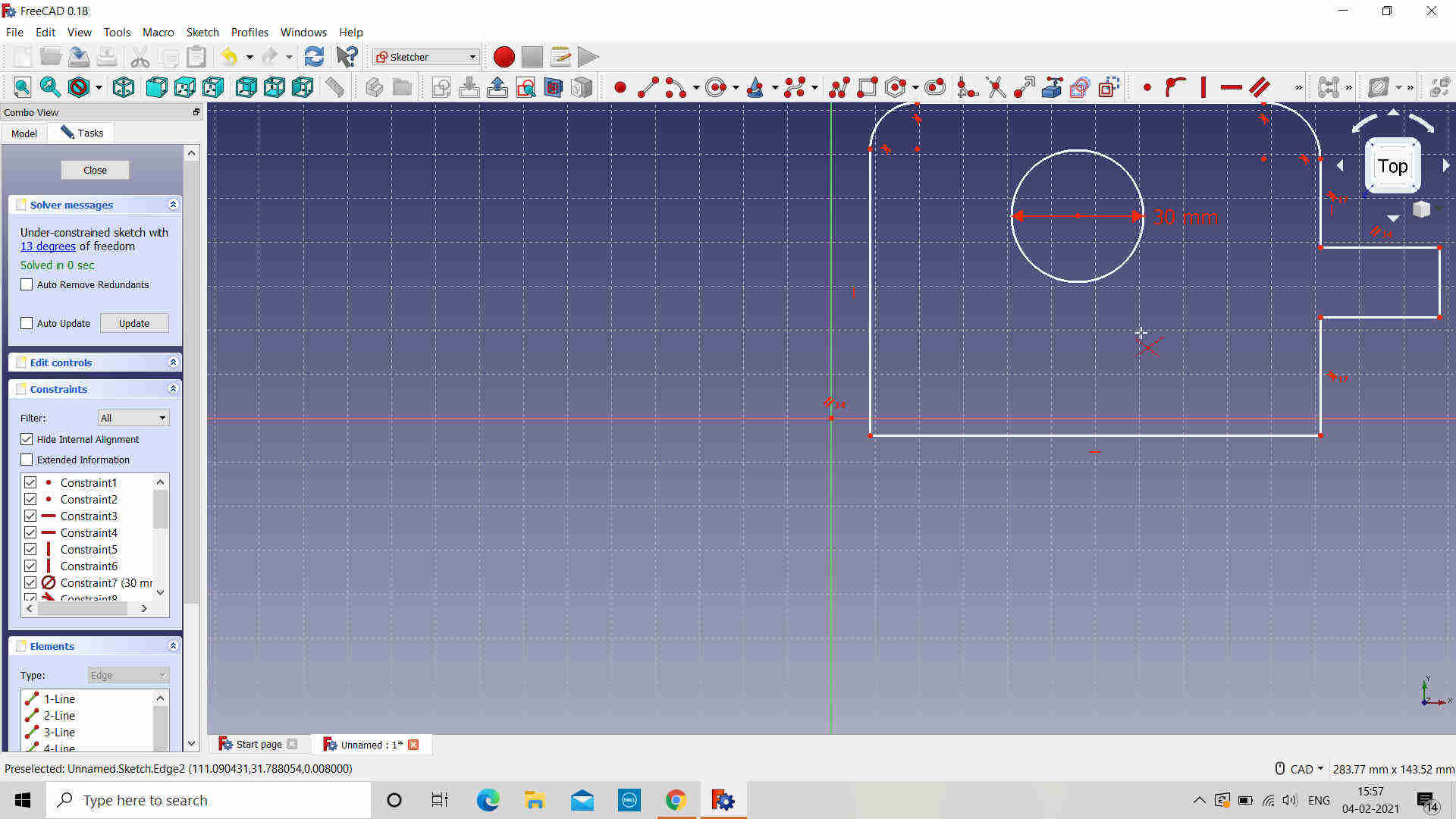
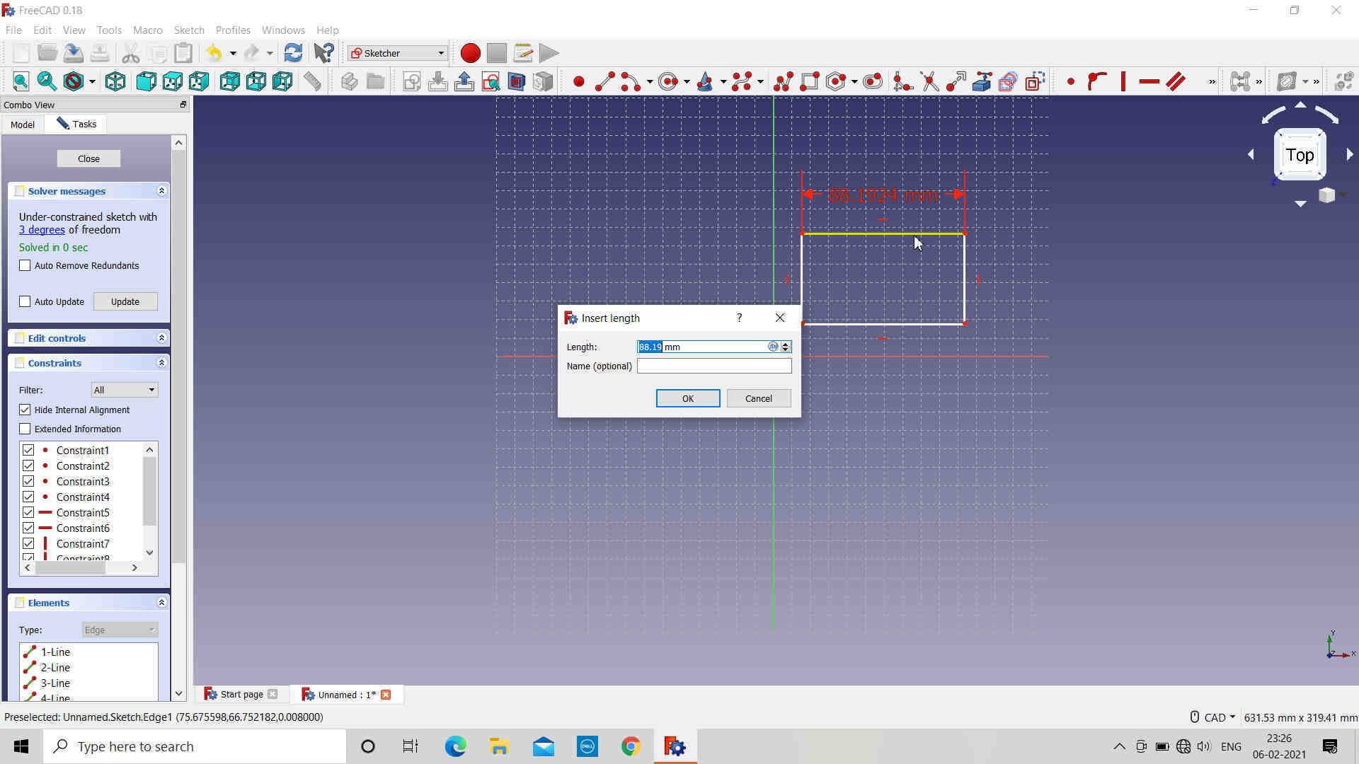
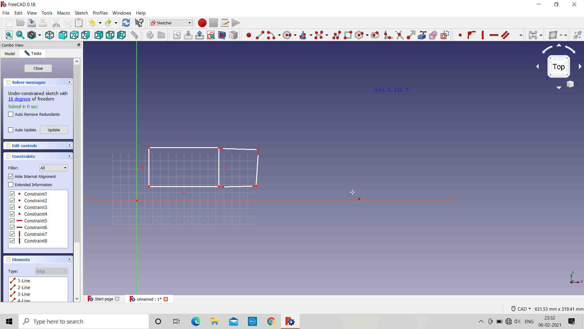
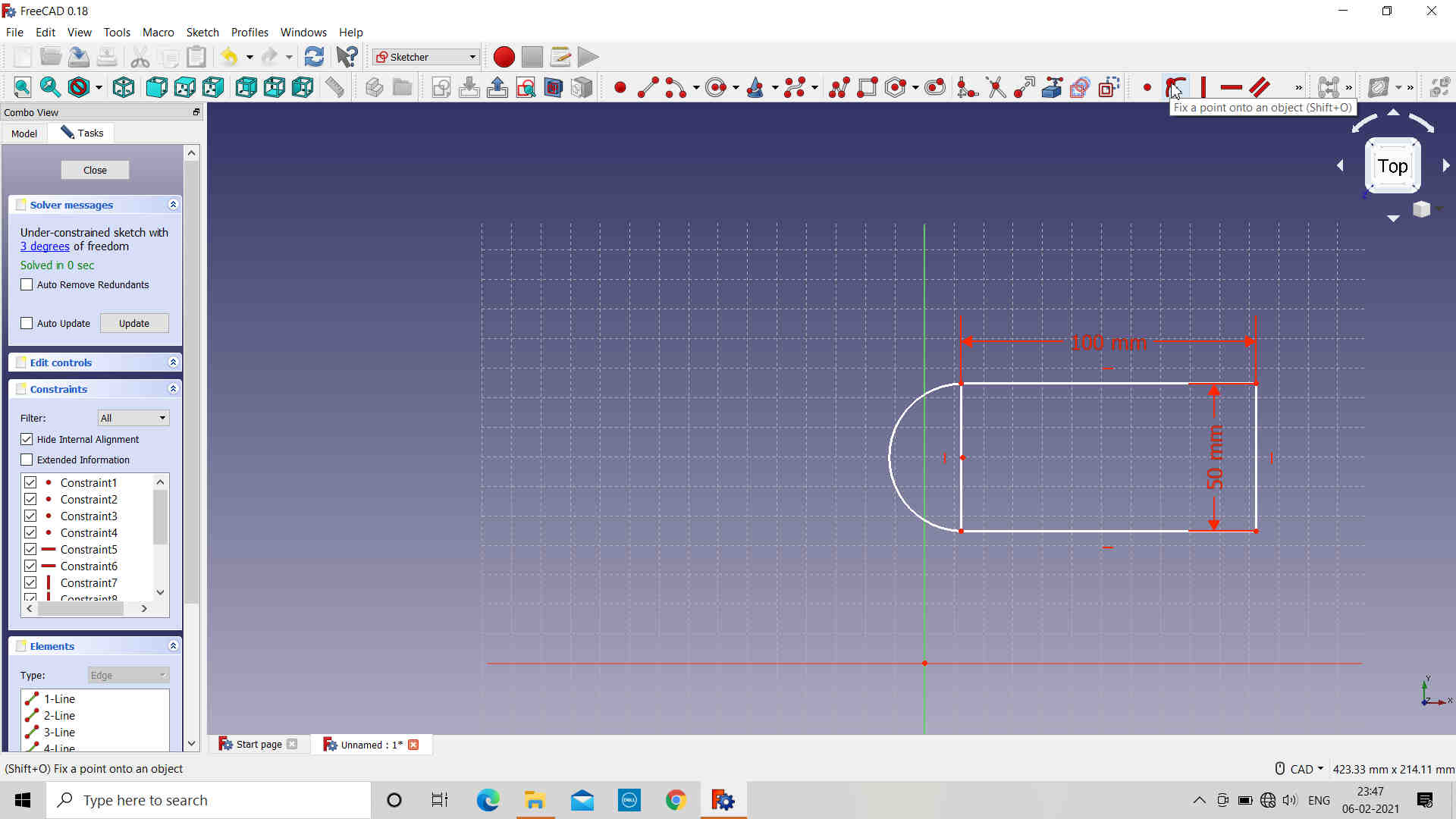
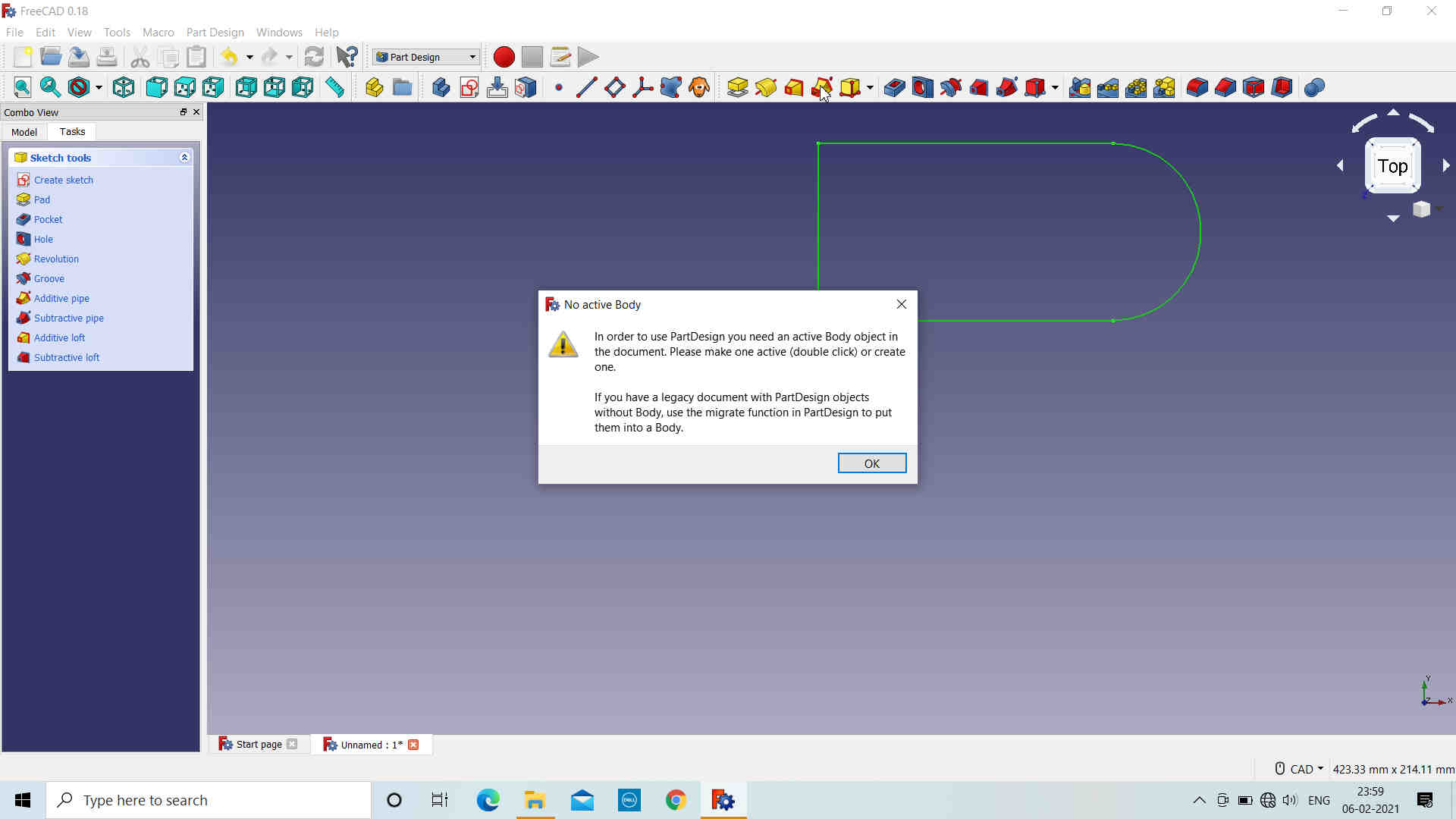
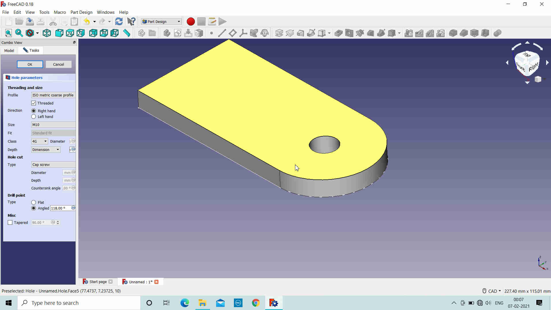
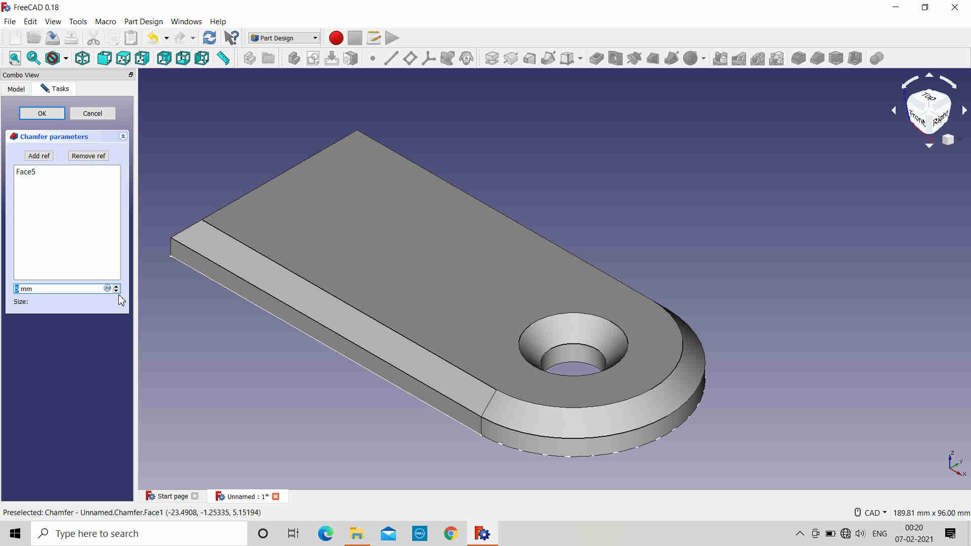
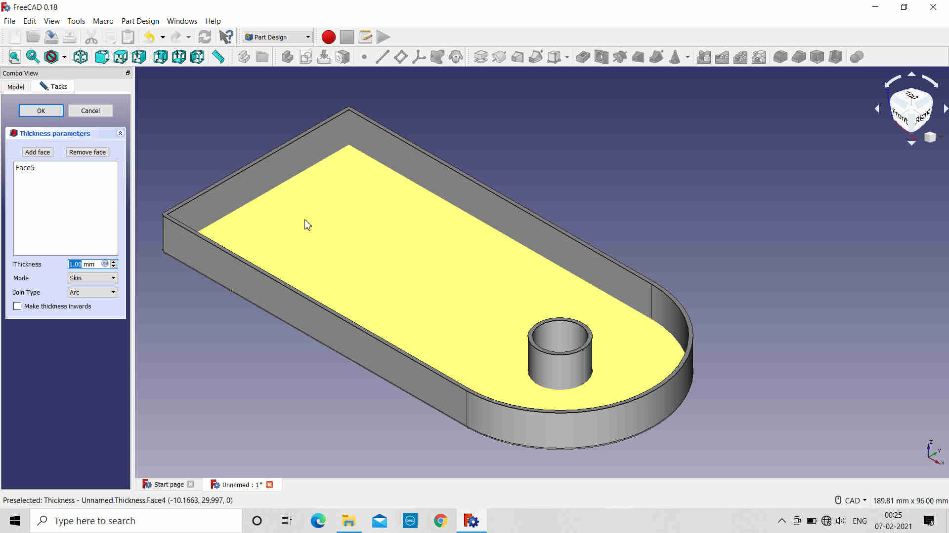
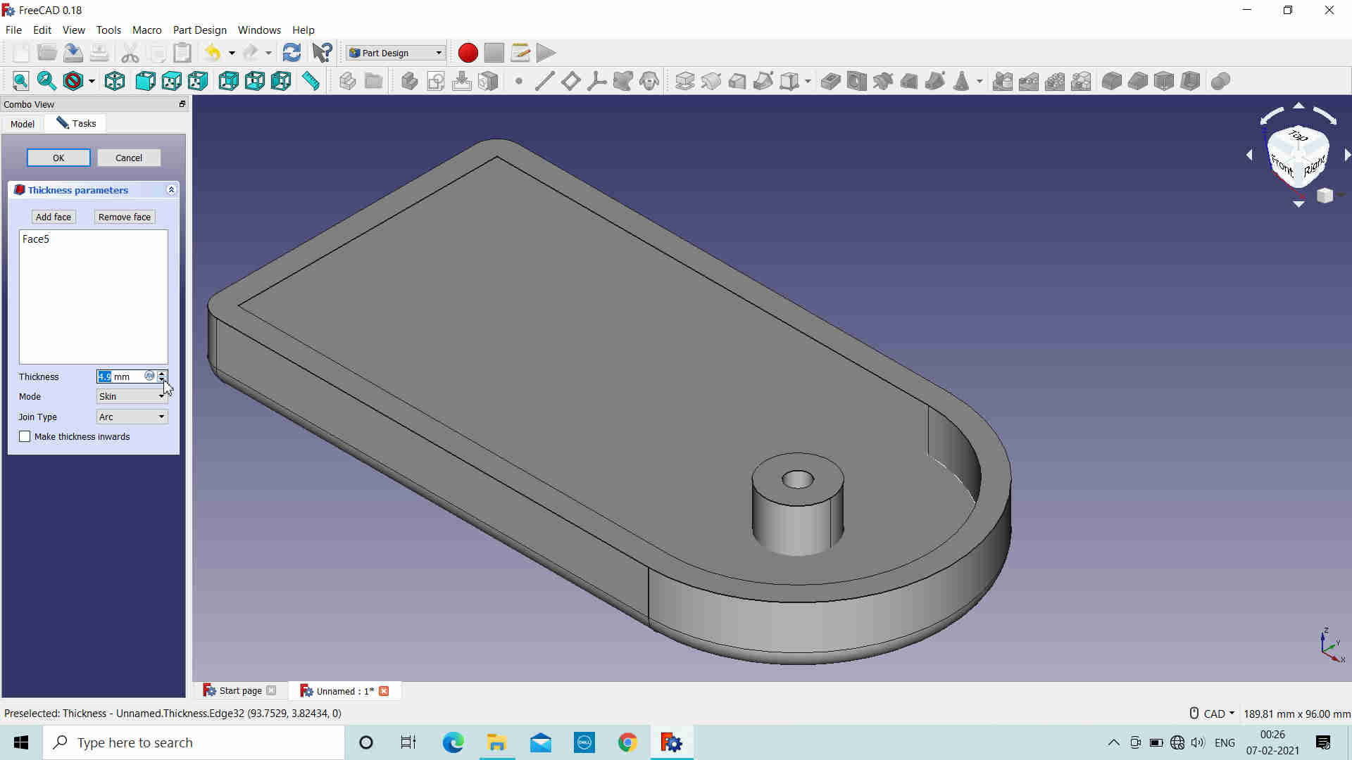
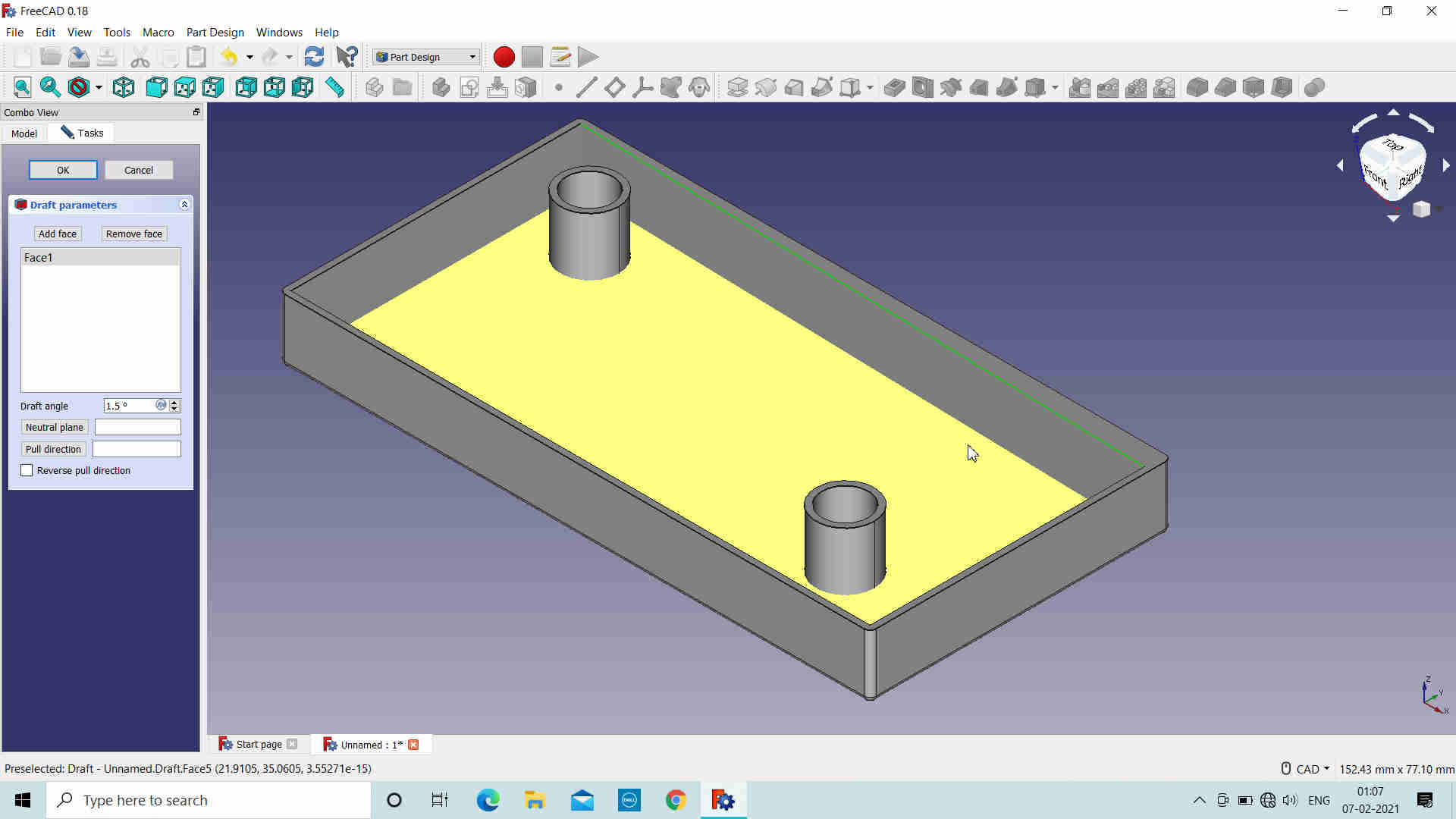
Free CAD:
It is open source 3D design software which is highly recommended by Dr. Neil. I downloaded and tried exploring it.


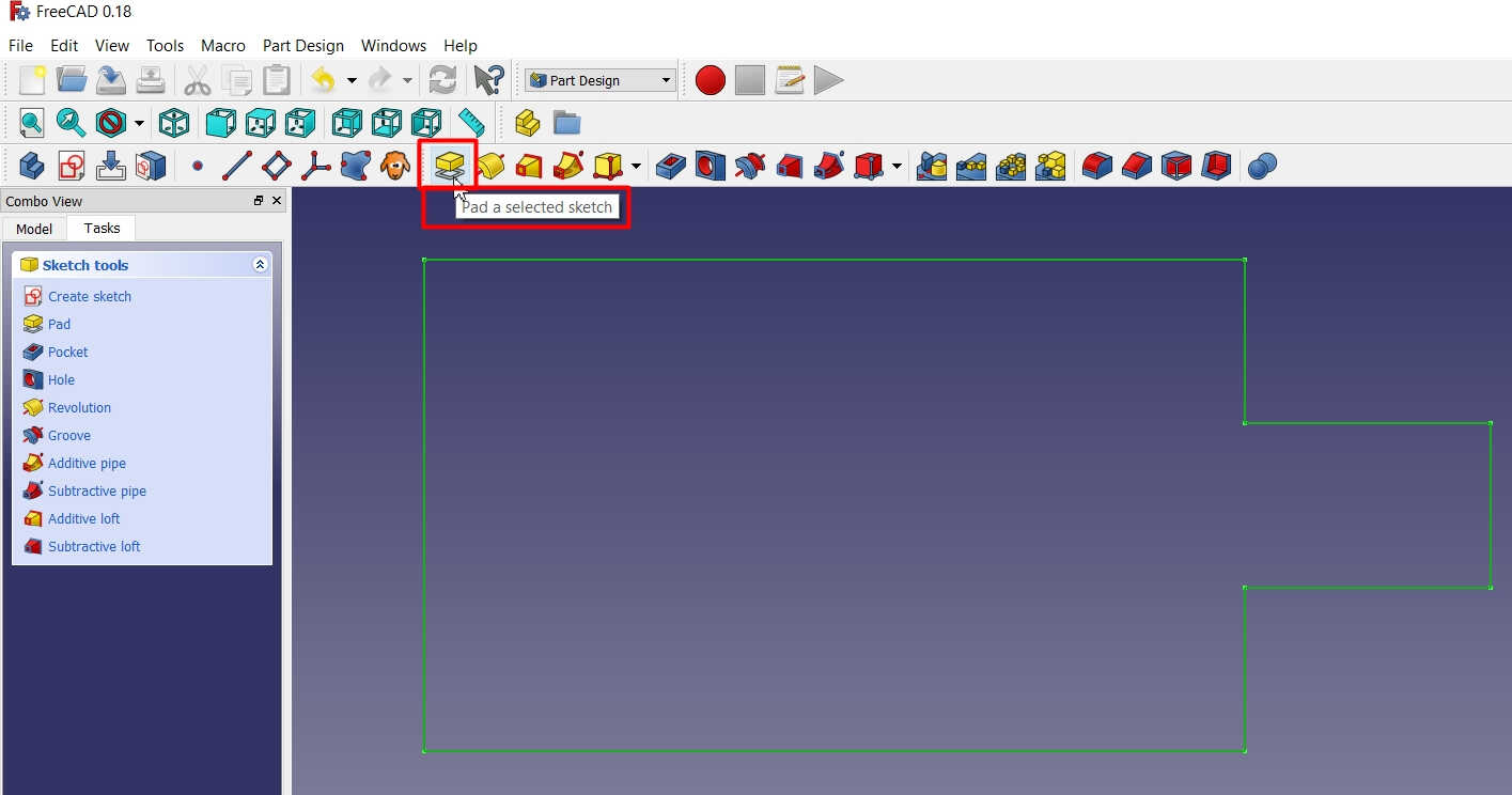
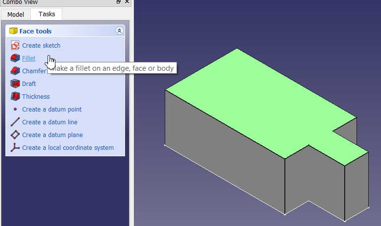
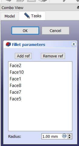
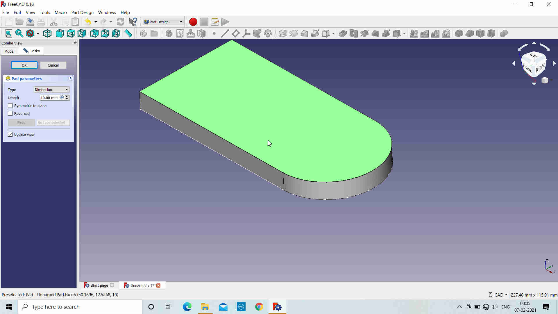
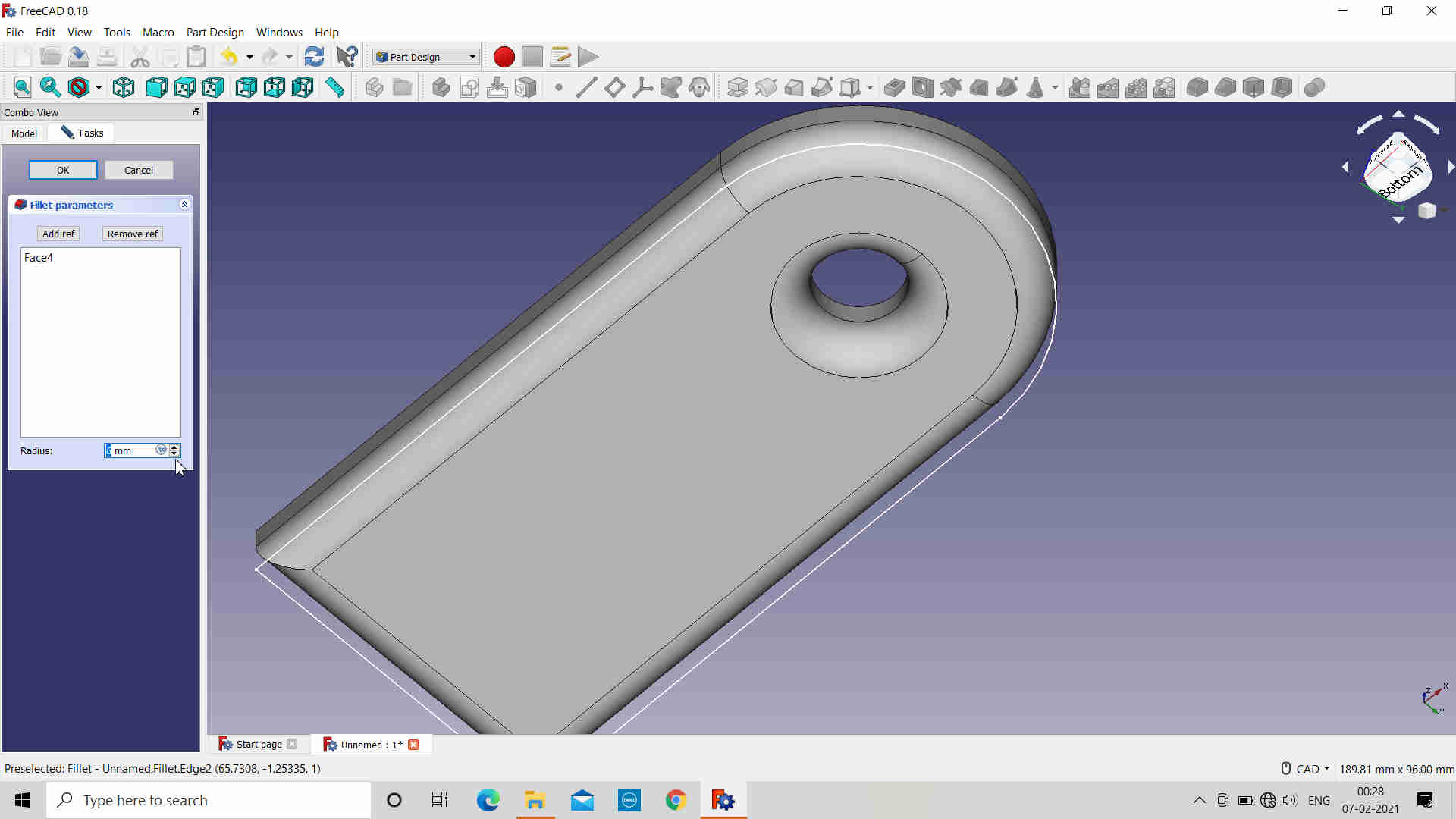
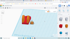
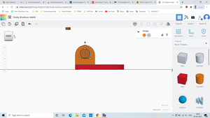
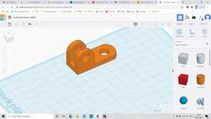
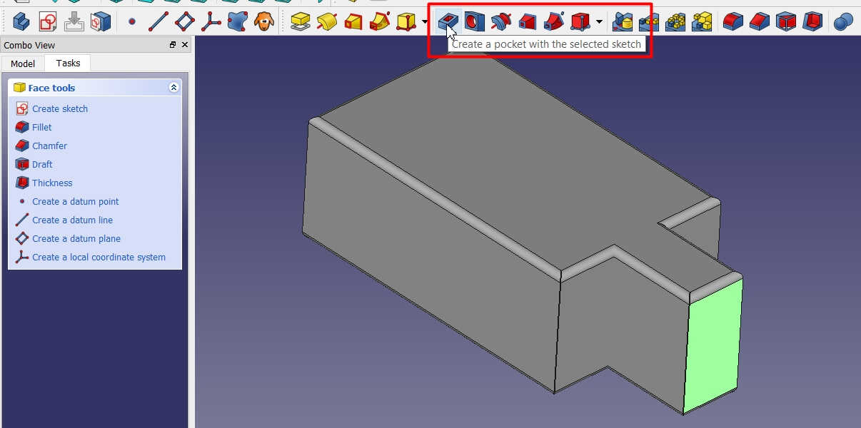 Object with Fillets
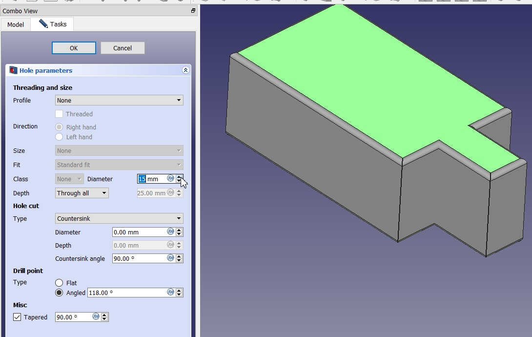 Tried creating the Hole in the Object but couldnt as the diamter of the Hole was very small as per the parameters. So, left it as it is.
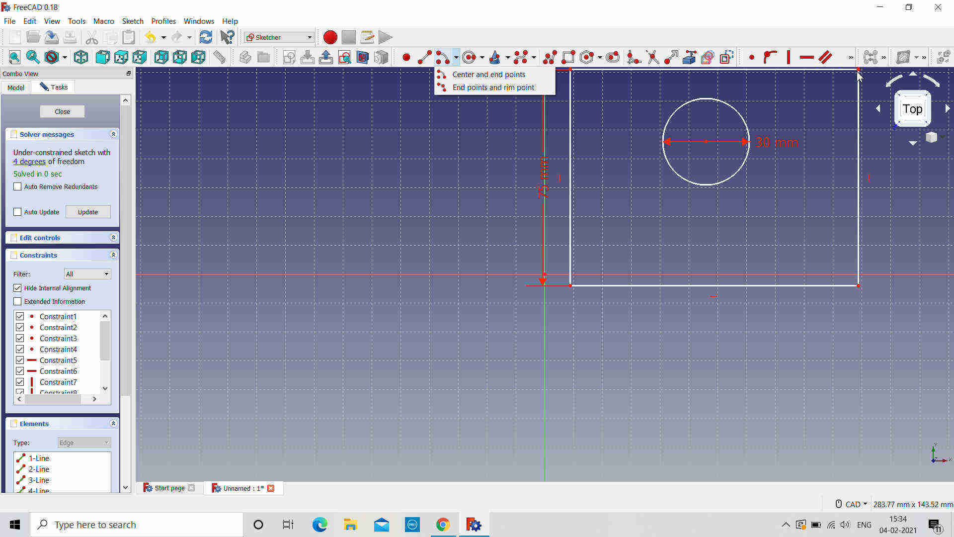

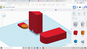
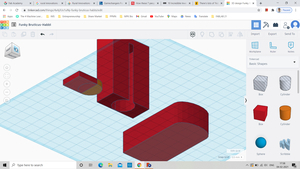
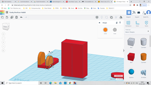
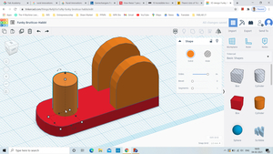
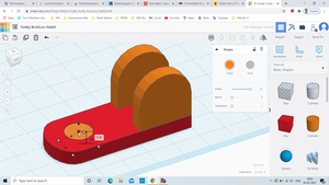
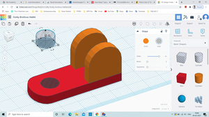
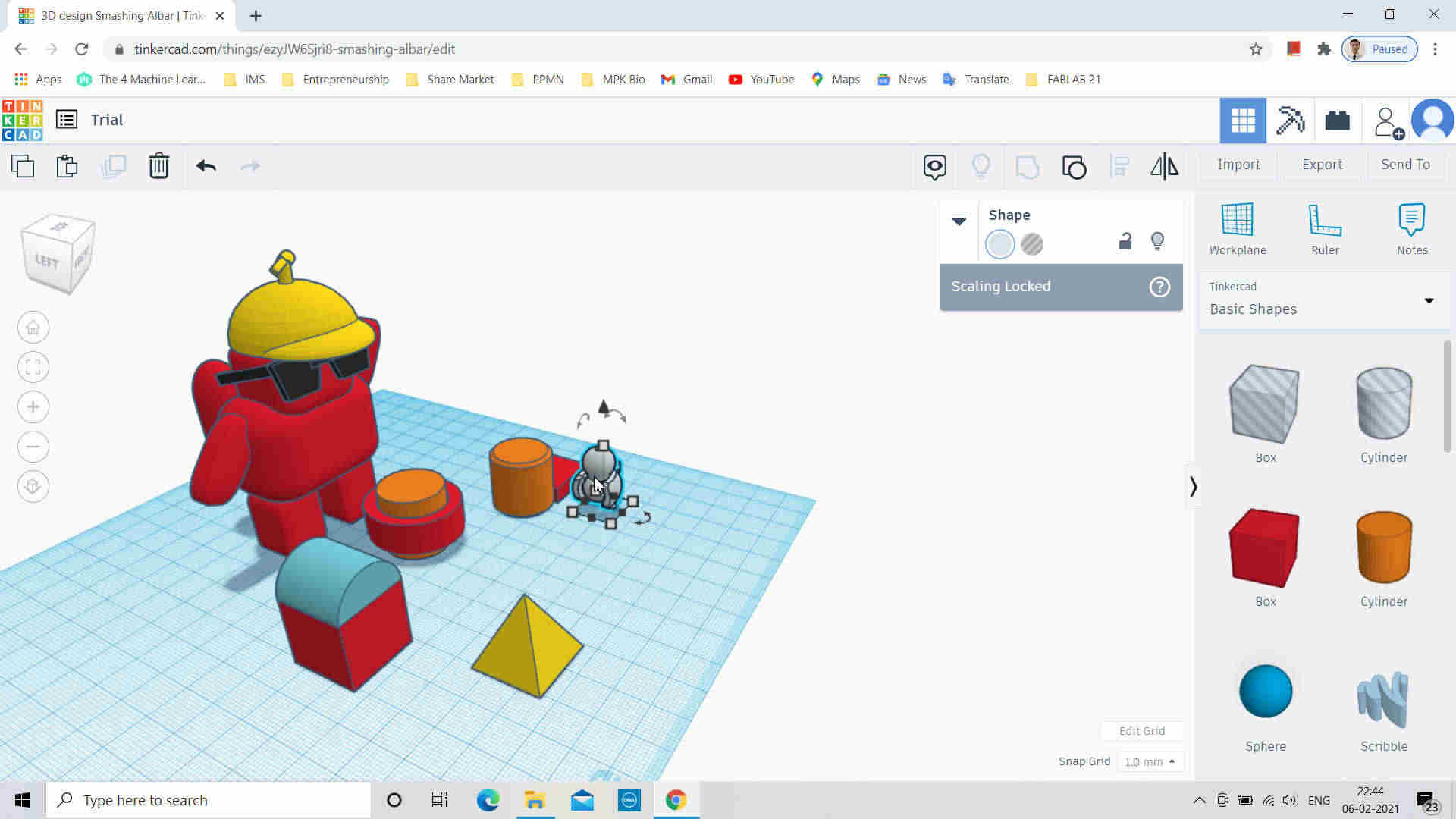
Tinker CAD:
Considered as the Design Software for the Beginners and Kids. It also has feature to design Electronic Circuits. Forgot to take Screenshots from the beginning.
- Open TinkerCad in the Browser
- Sign Up or Log In if already created an Account
- Click on Create New Design
- Select the Shapes to draw from the Right Side. Drag them on the WorkPlace
- Select the Object and assign the dimensions to it.
Rhino6:
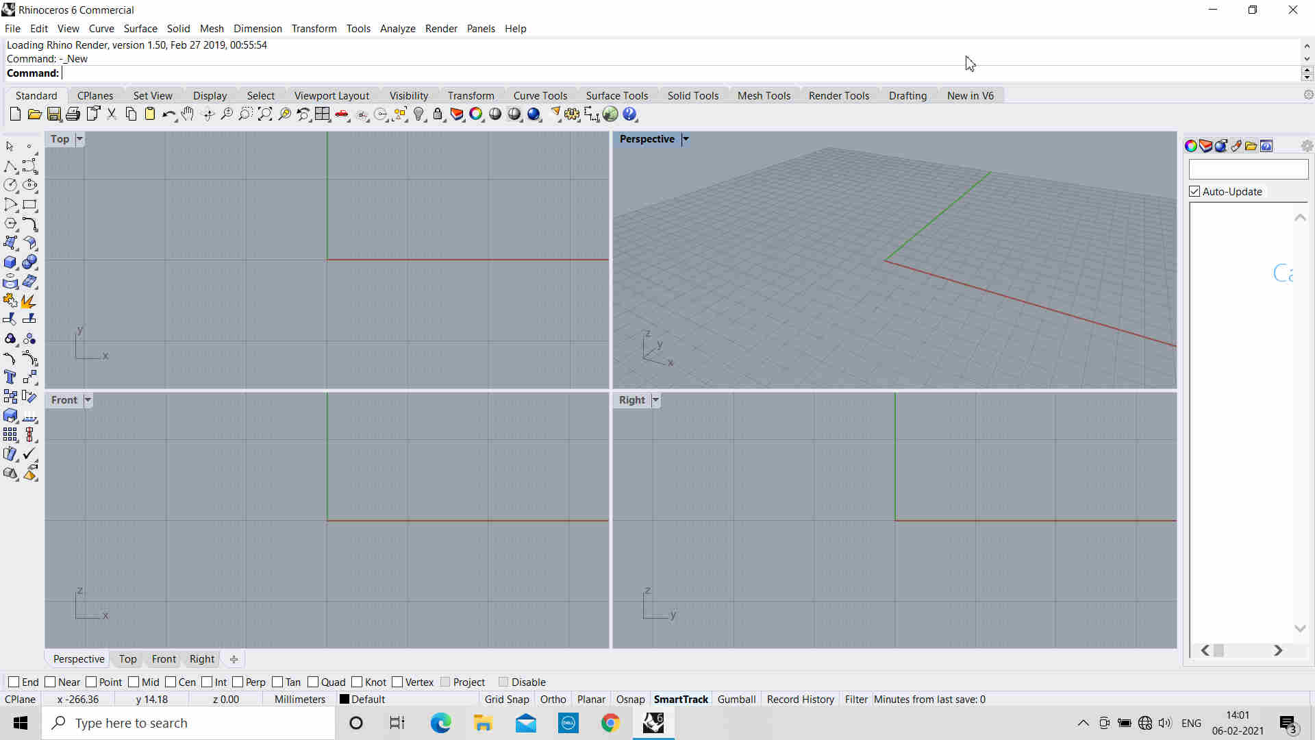
Four Views after opening the Rhino-6 Software
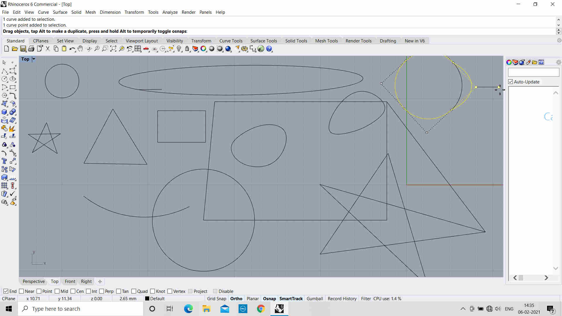
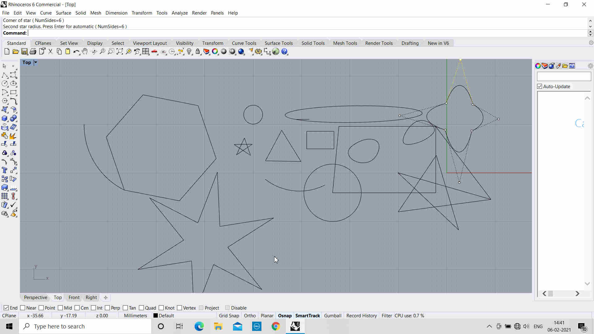
Tried drawing few 2D shapes
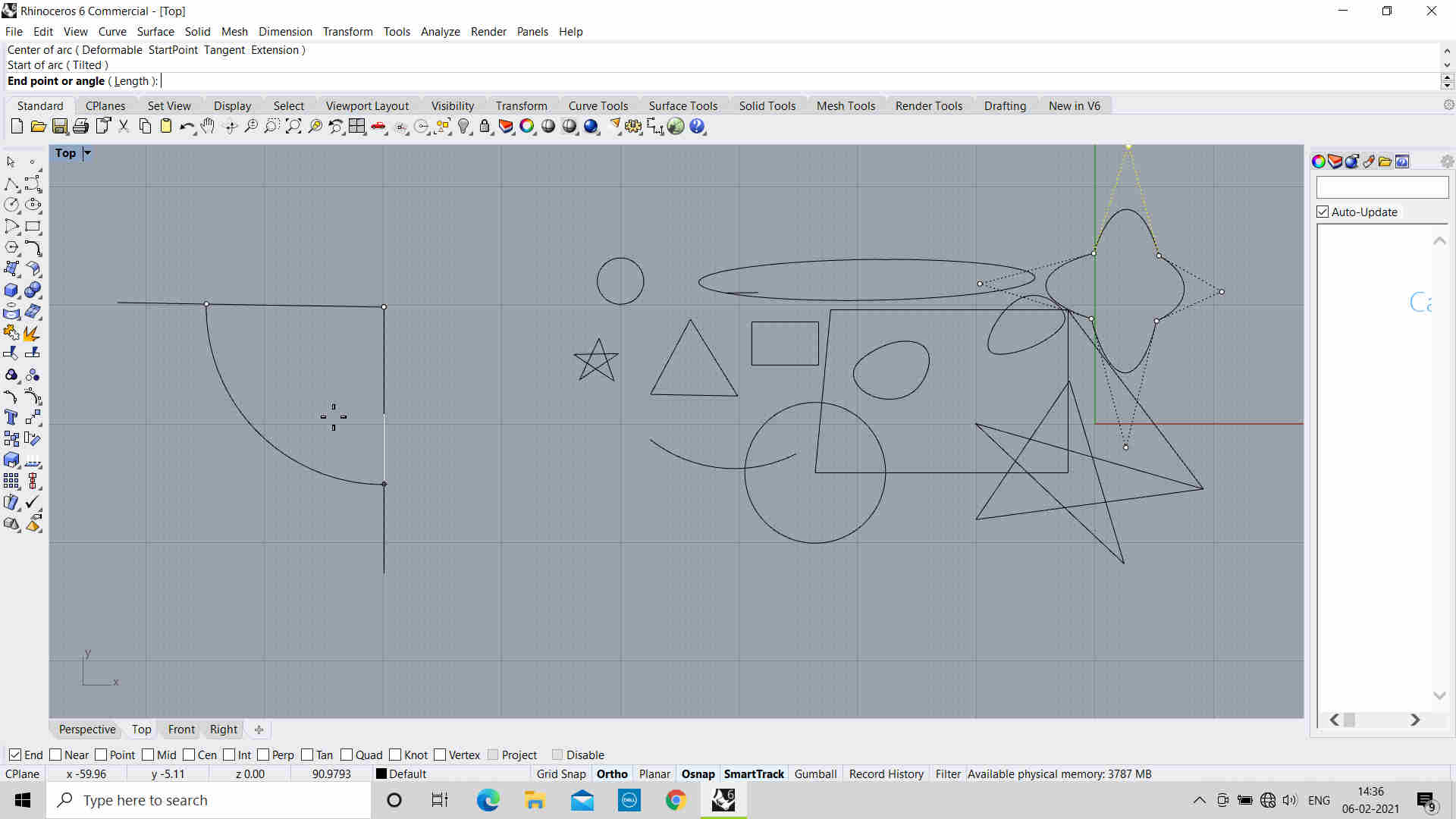
Tried an Arc
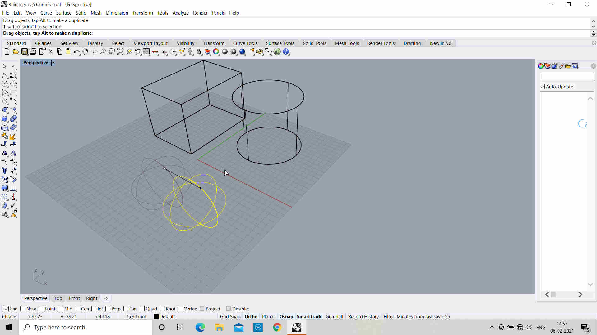
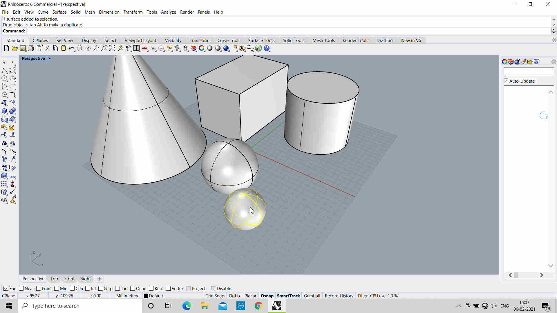
Tried editing Shape of Sphere with Editing lines
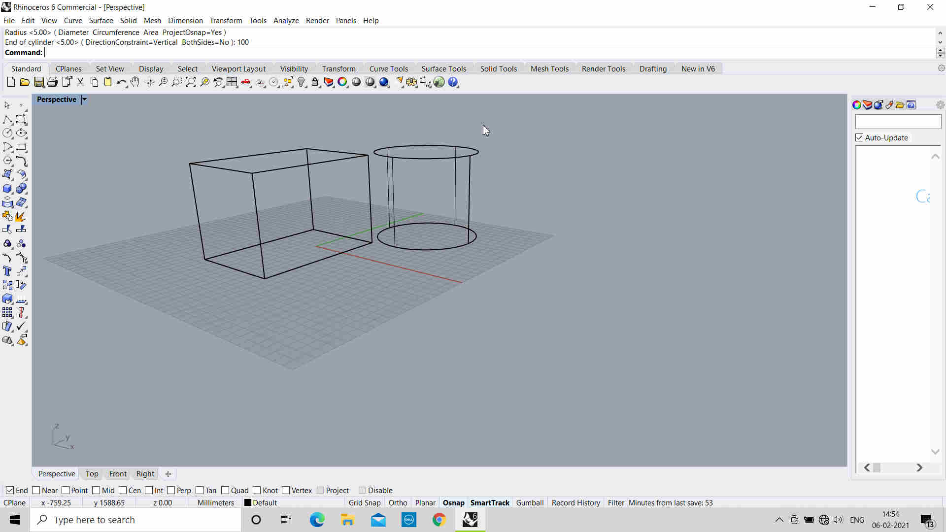
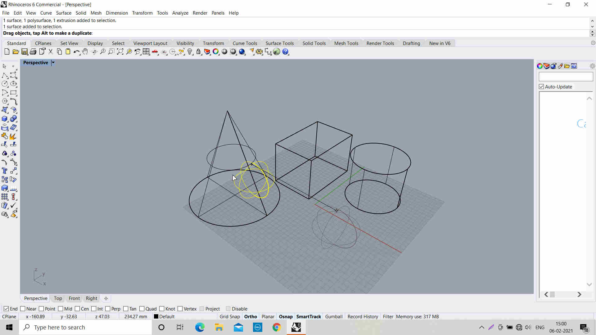
Tried drawing 3D shaped by defining dimensions
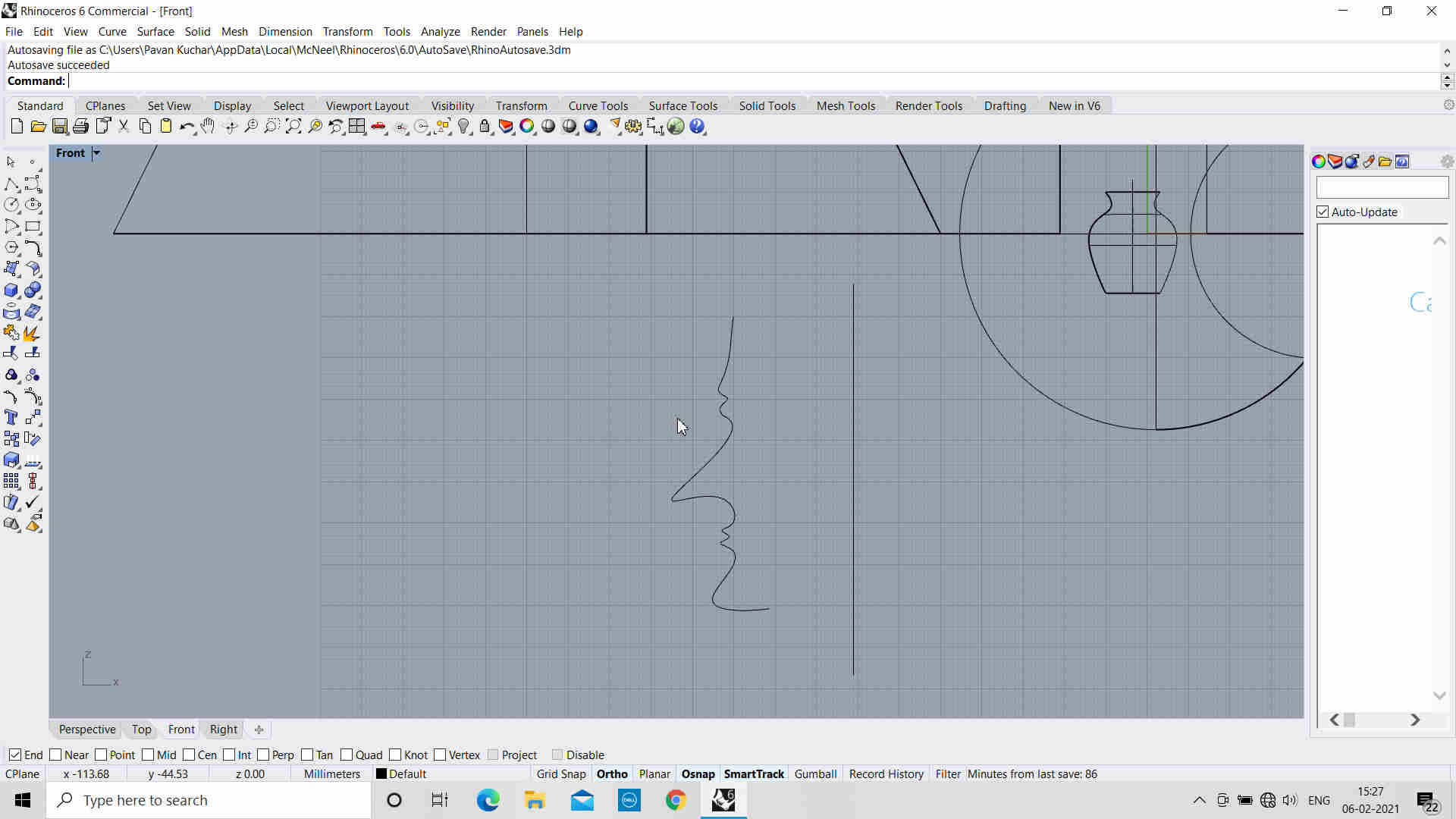
Tried the Revolve function to create a Vase by rotating along one axis by 360 degrees
Tried the Solid view of the Objects
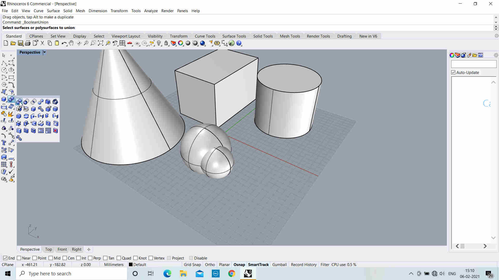
Tried Boolean Union of two spheres
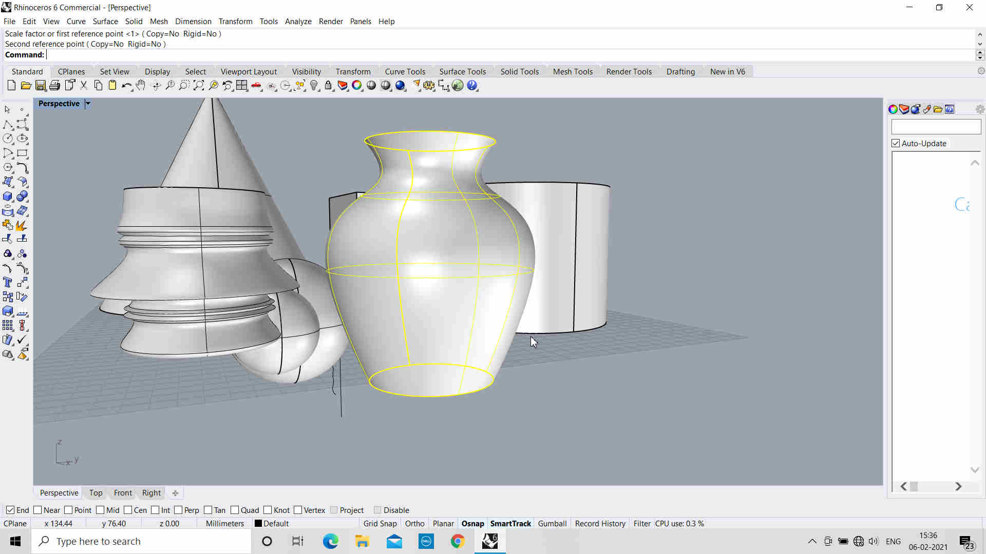
created a Vase by revolve function
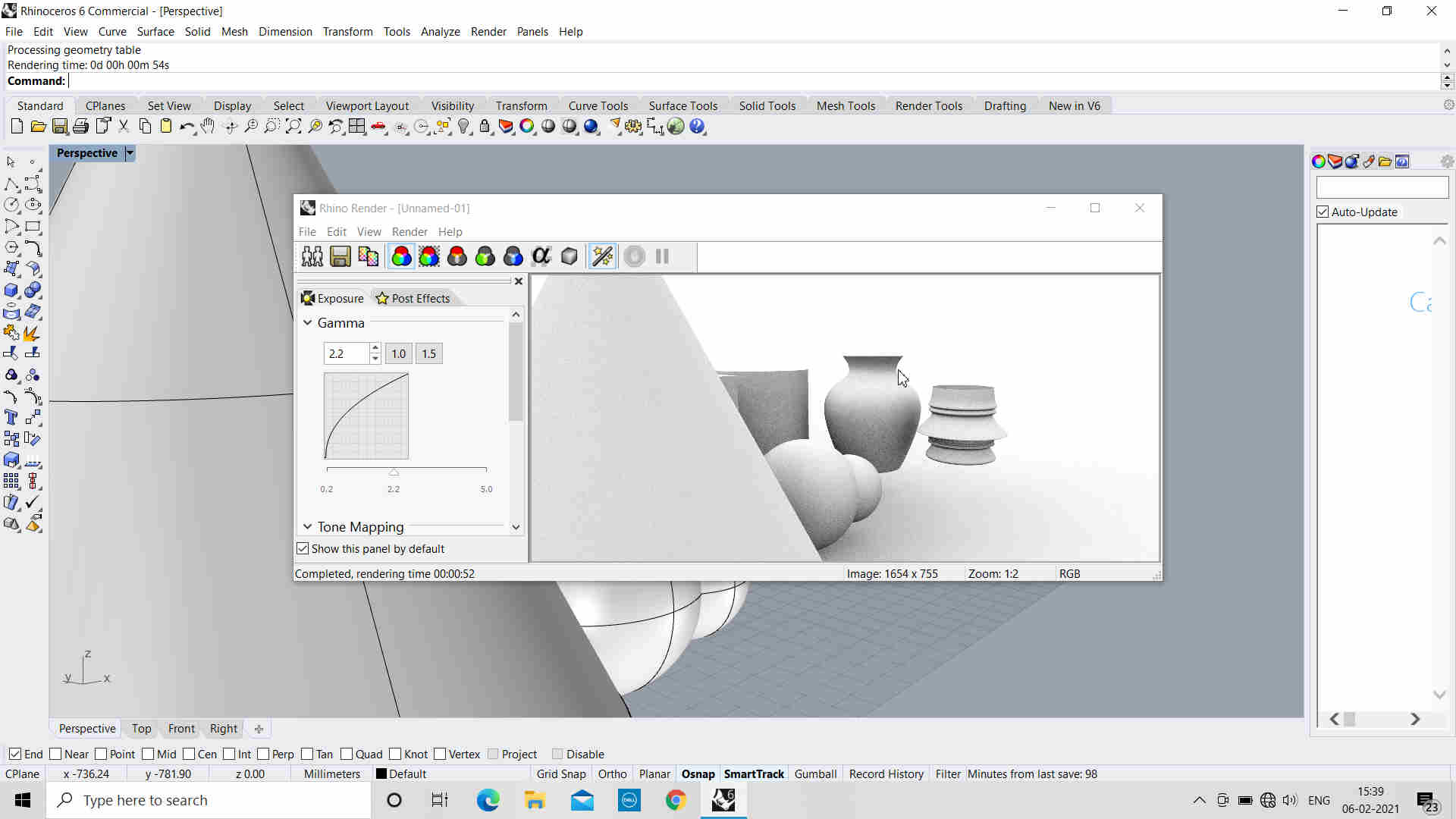
Tried Rendering
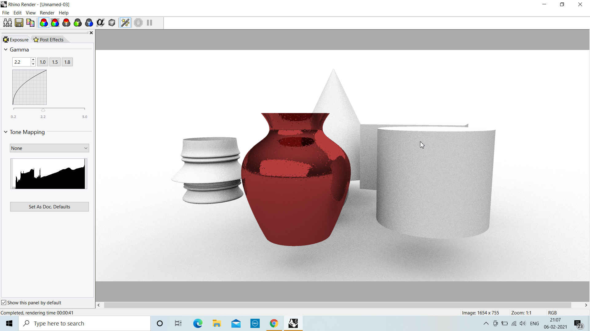
Change the Material properties and rendered it
For Designing a Vase in Rhino-6, I followed the following Steps:
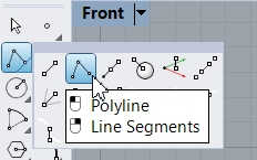 Selected Lines for Drawing Straight Lines | 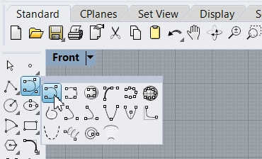 Selected PolyLines to Draw Curves of the Vase | 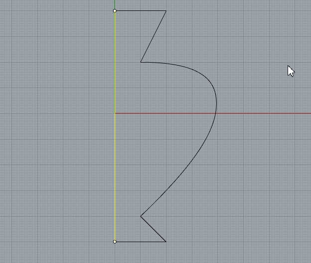 Drew the Shape of the Vase along a Straight Line in Center |
|---|
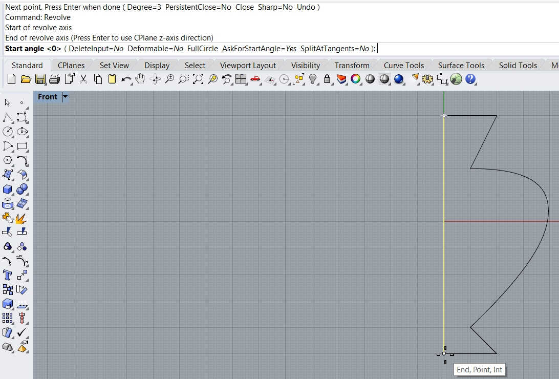
Drew the Shape of the Vase along a Straight Line in Center
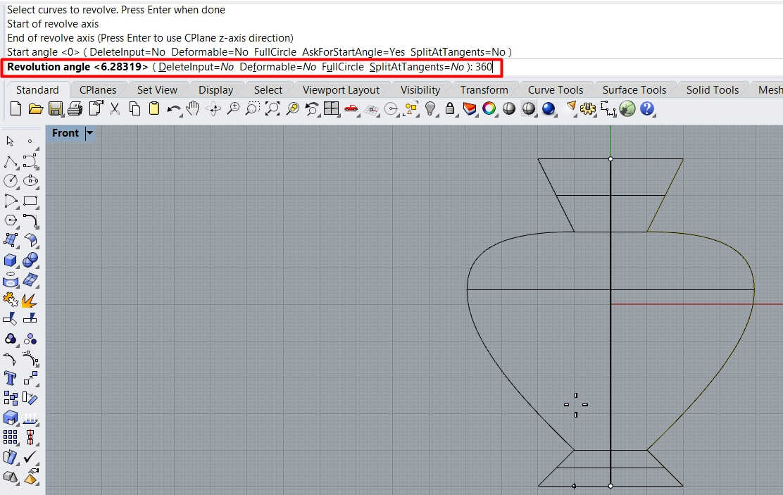
Used Revolve Command; Defined the Start and End Angles of Revolution and Axis
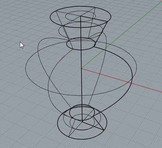 Object in Wireframe View | 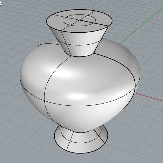 Object in Shaded Viewport View |
|---|
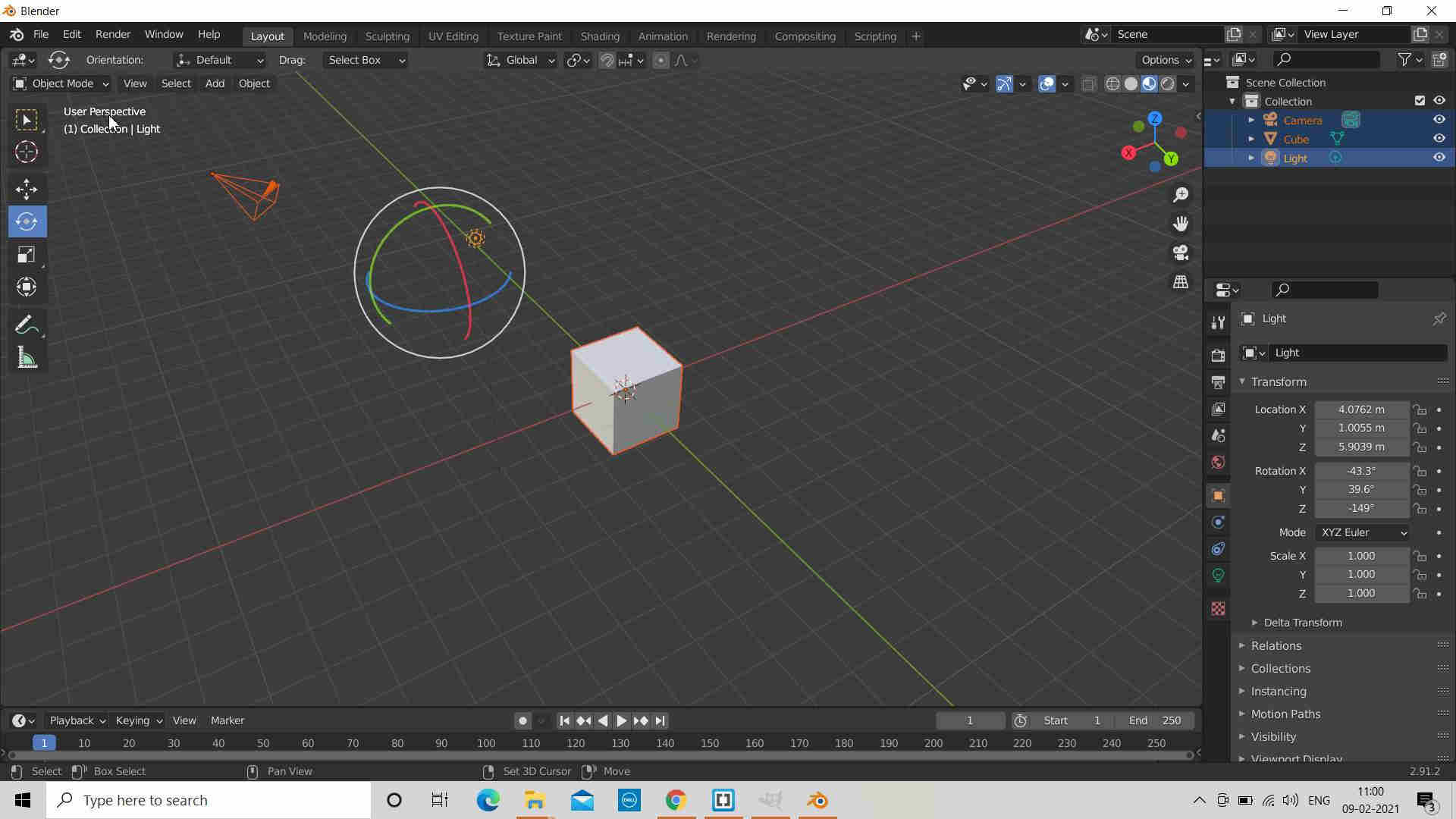
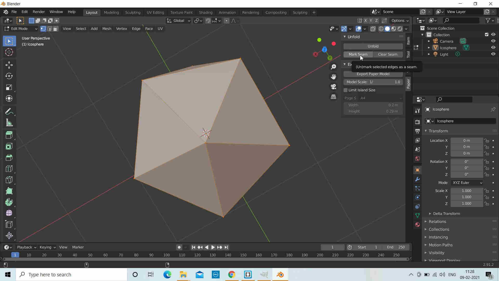
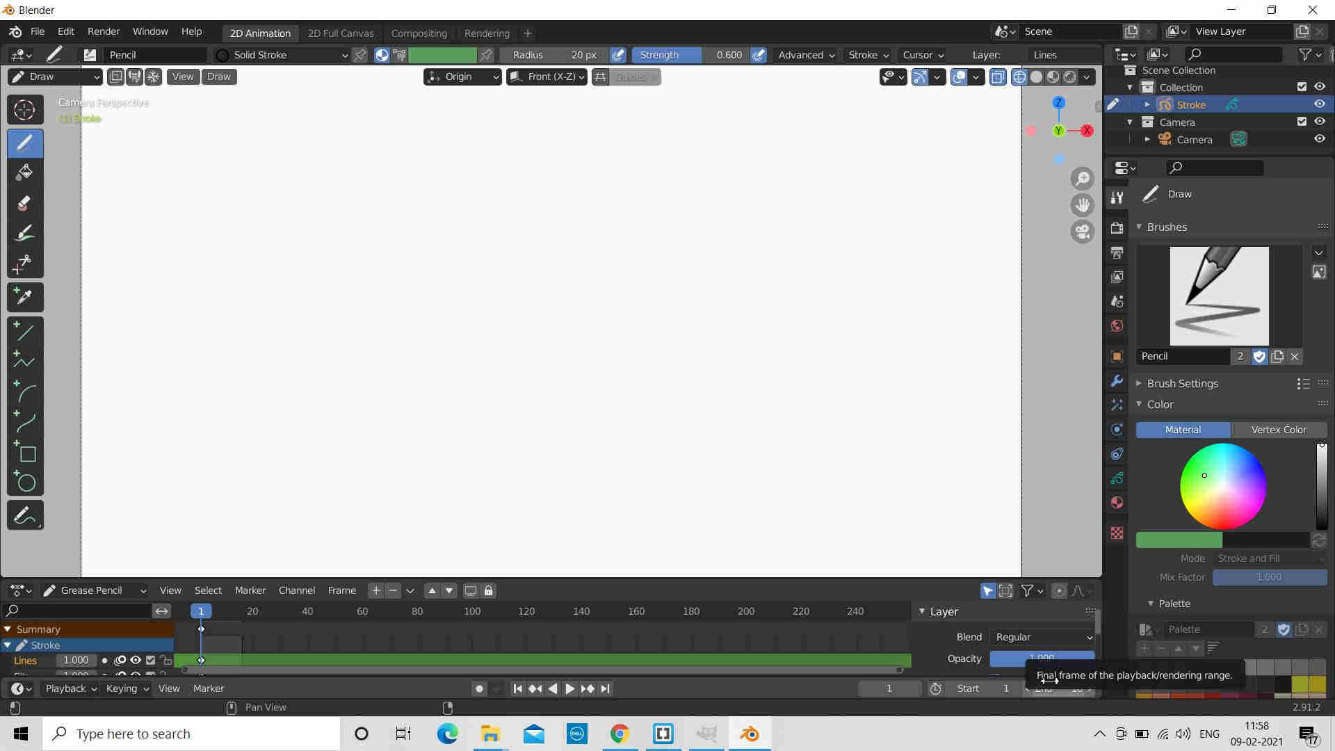
blender
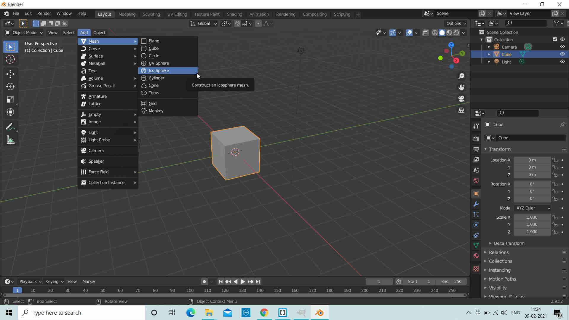
Rahul Kanojia took our hands on tutorial about blender which is very easy to handle, has many functionalities and features, open source software, light weight.Working Notes: for blender:
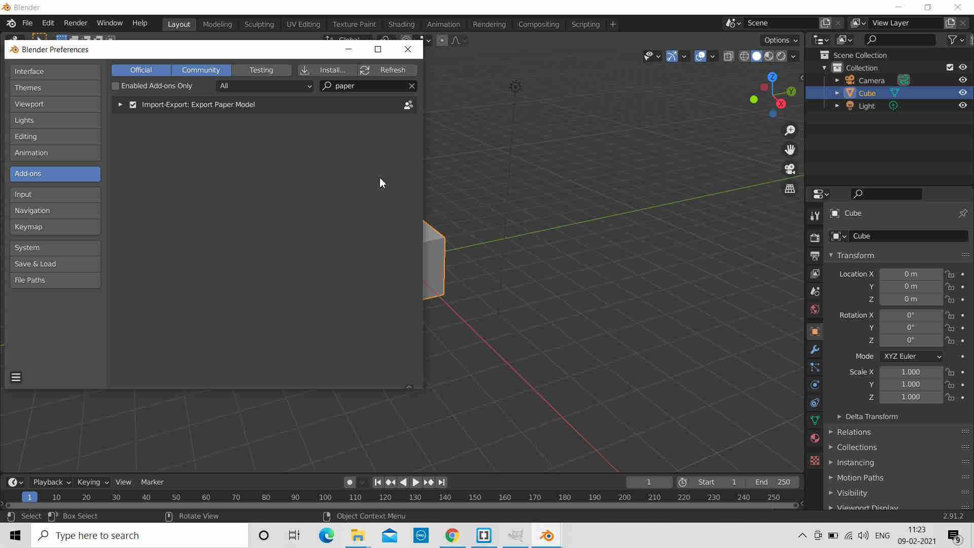
You can also get the shortcut keys used in blender.
Go to the edit menu select Blender Preference and go to the Keymap
Some of keys are:
0 for camera mode
1 for front view
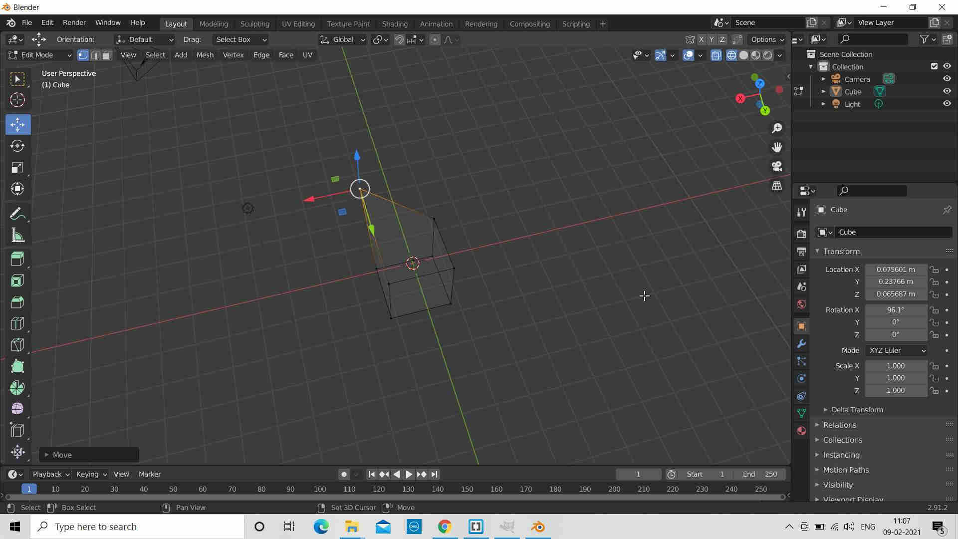
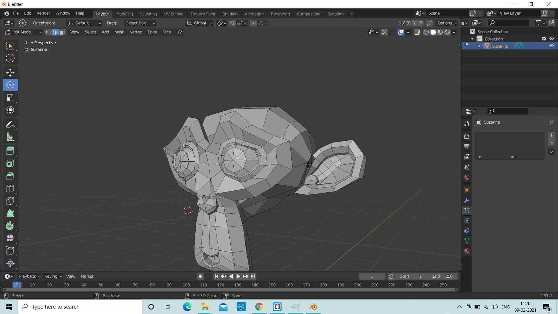
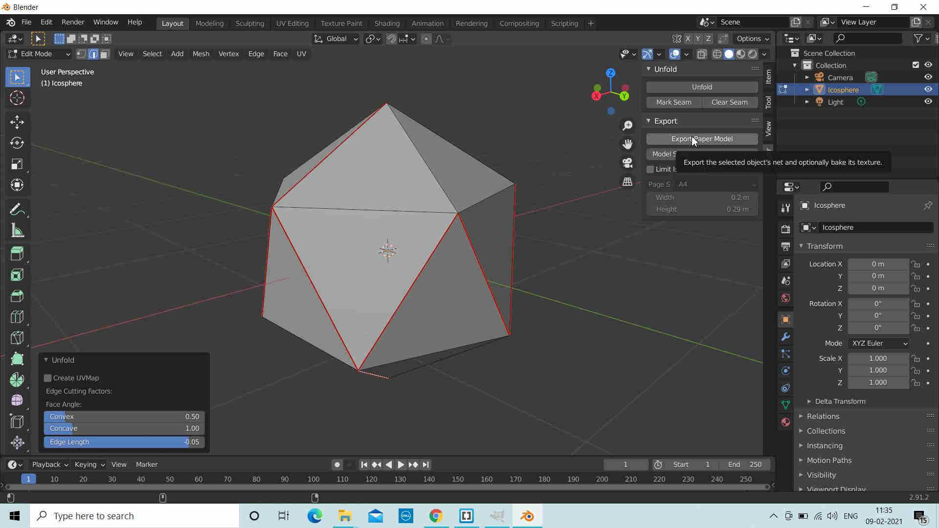
For editing given object, Select given object and Go to the Tab and change the object mode to edit mode.
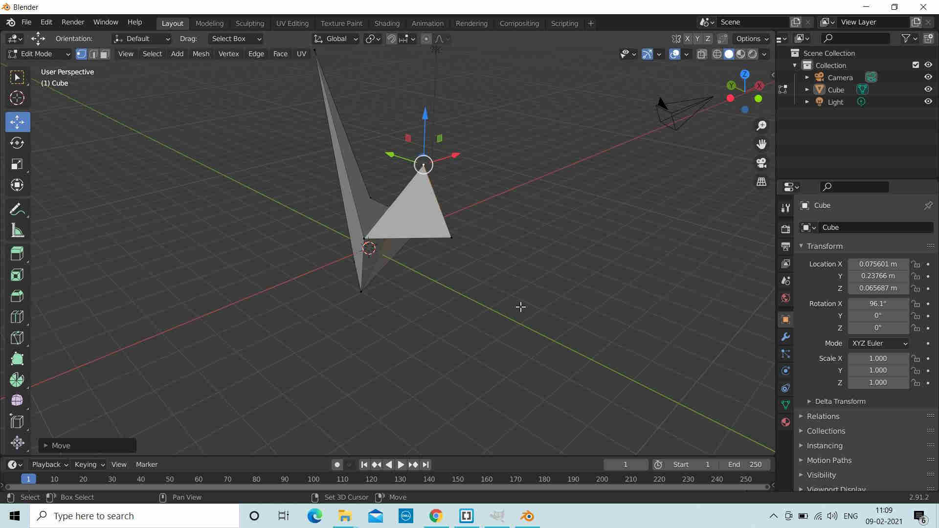
You can change the object according to Vertex
Select vertex point,press G and move it along X axis.
For Pan: Prell Shift + Scroll button on mouse
For Tilt: Press and Move the Scroll button
For
Zoom: Scroll in and out by the Scroll button of mouse.
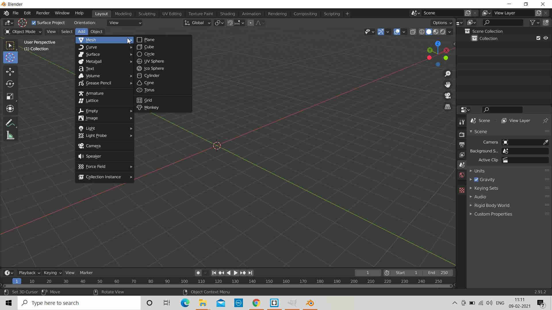
You may explore and change the shortcut keys from the File --> Preferences --> Add ons. Numpad key 5 can be used to switch from Perspective view to Ortho view.
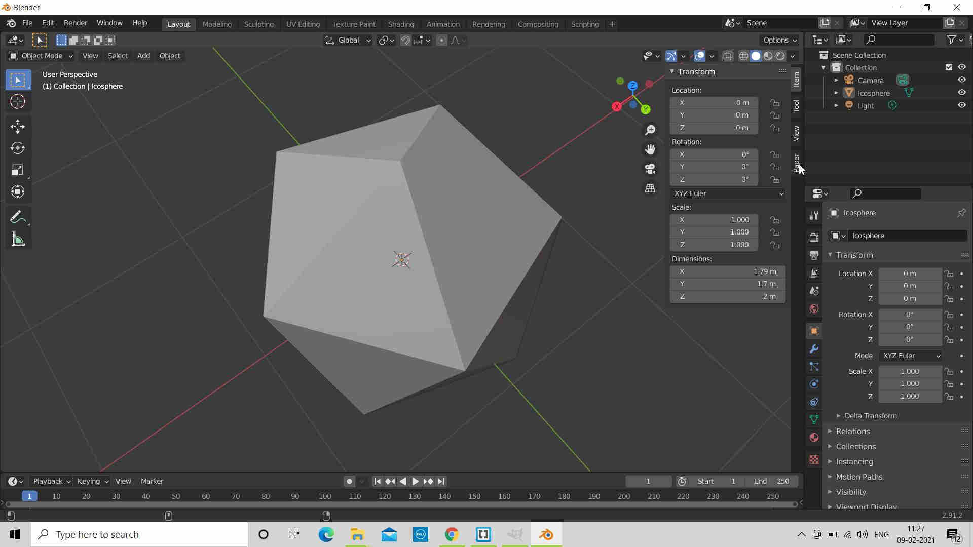
Pressing G and then X will make the selected object to move only along the X axis. Same could be done for the other Y and Z axes as well.
Press R and the Y will make the selected object to rotate only along the Y axis. Same could be done for the other X and Z axes as well.