Objective of Group Assignment:
In group assignment We have to test equipment in our lab to observe the operation of a microcontroller circuit board (in minimum, check operating voltage on the board with multimeter or voltmeter and use oscilloscope to check noise of operating voltage and interpret a data signal)
And Document your work (in a group or individually)
Individual Assignment:
Redraw one of the echo hello-world boards or something equivalent, add (at least) a button and LED (with current-limiting resistor) or equivalent input and output, check the design rules, make it, test it.
Learning outcomes
1) Select and use software for circuit board design 2) Demonstrate workflows used in circuit board design
About Group Assignment:
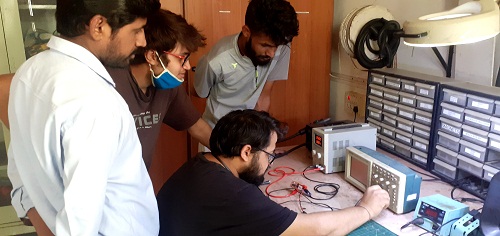
In this week of group assignment we have tested the electrinics equipment like Multimeter,DSO(Digital Storage Oscilloscope.
So we have tested the above devices one by one and Observe the characterstics available in our fablab at vigyan ashram
and observed the operation of Microcontrooler Circuit board
Equipment need to be tested
1) Multimeter
2) Power Supply
3) Digital Storage Oscilloscope
Multimeter
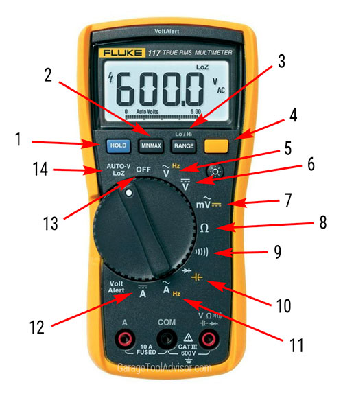
As we know the multimeter is common equipment which is generally used to measure the various parameter eletrcial parameter like resistance, voltage, current , capacitance etc.
The basic stucture of multimeter as shown below
In our FABLAB magger make multimeter available for testing the various values and test.
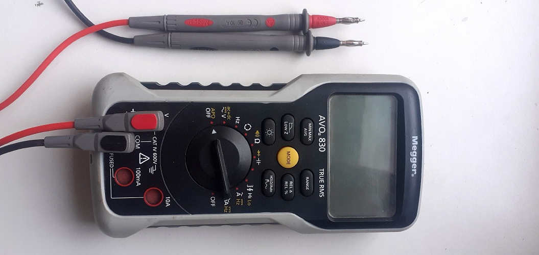
first We have perform the continuity test:
This test is generally used for determining the damaged components or broken conductors in a circuit. It can also help in determining if the soldering is good, if the resistance is too high for flow of current or if the electrical wire is broken between two points.
We have measured the AC/DC Voltage ,values of various resitances which is used in PCB board,values capacitance.
So above parameter we have checked for testing the PCB board.
Power Supply:(DC Rgulated Power Supply )
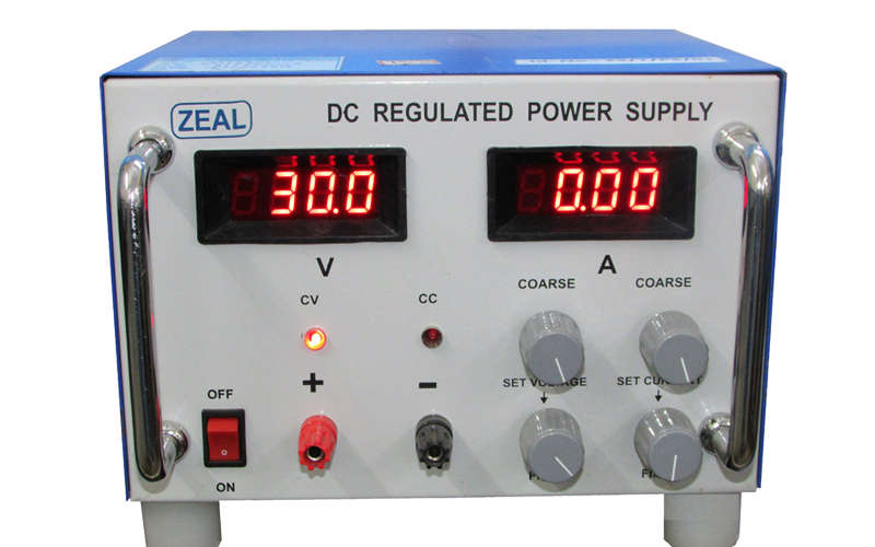
A DC regulated power Supply convert the Unregulated AC voltage to a constance DC voltage.
A regulated power supply is used to ensure that the output remains constant even if the input changes.
In our fablab METRAVI make model NO. -RSP3005 available.
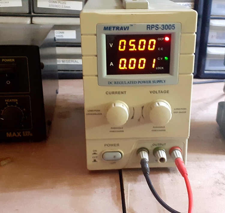
So We have tested this by applying the voltage to any electrical Device will get the current requied or the value of current flowing through wire is depends on the applied voltage.
The regulated power supply will accept an AC input and give a constant DC output. The figure below shows the block diagram of a typical regulated DC power supply.

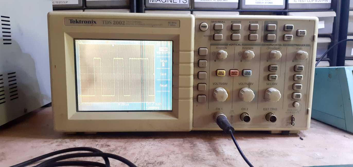
Digital Storage Oscilloscope
The digital storage oscilloscope is an instrument which gives the storage of a digital waveform or the digital copy of the waveform. It allows us to store the signal or the waveform in the digital format, and in the digital memory also it allows us to do the digital signal processing techniques over that signal. The maximum frequency measured on the digital signal oscilloscope depends upon two things they are: sampling rate of the scope and the nature of the converter. The traces in DSO are bright, highly defined, and displayed within seconds.
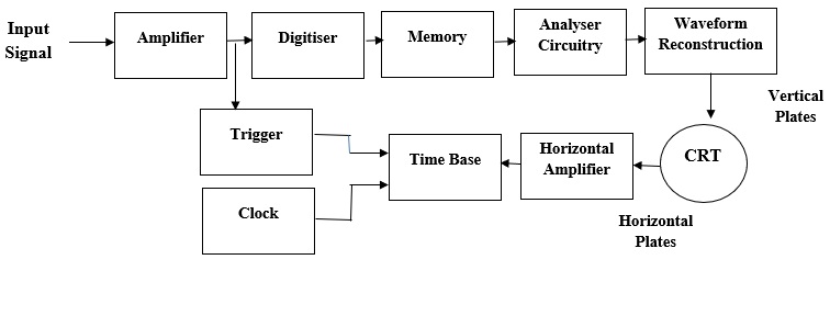
Block Diagram of Digital Storage Oscilloscope
The block diagram of the digital storage oscilloscope consists of an amplifier, digitizer, memory, analyzer circuitry. Waveform reconstruction, vertical plates, horizontal plates, cathode ray tube (CRT), horizontal amplifier, time base circuitry, trigger, and clock. The block diagram of the digital storage oscilloscope is shown in the below figure.
Explanation
1. first digital storage oscilloscope digitizes the analog input signal.
2. then the analog input signal is amplified by amplifier if it has any weak signal.
3. After amplification, the signal is digitized by the digitizer and that digitized signal stores in memory.
The analyzer circuit process the digital signal after that the waveform is reconstructed
DSO Operational Modes
1. Roll Mode: In roll mode, very fast varying signals are displayed on the display screen.
2. Store Mode: In the store mode the signals stores in memory.
3. Hold or Save Mode: In hold or save mode, some part of the signal will hold for some time and then they will be stored in memory.
These are the three modes of digital storage oscilloscope operation.
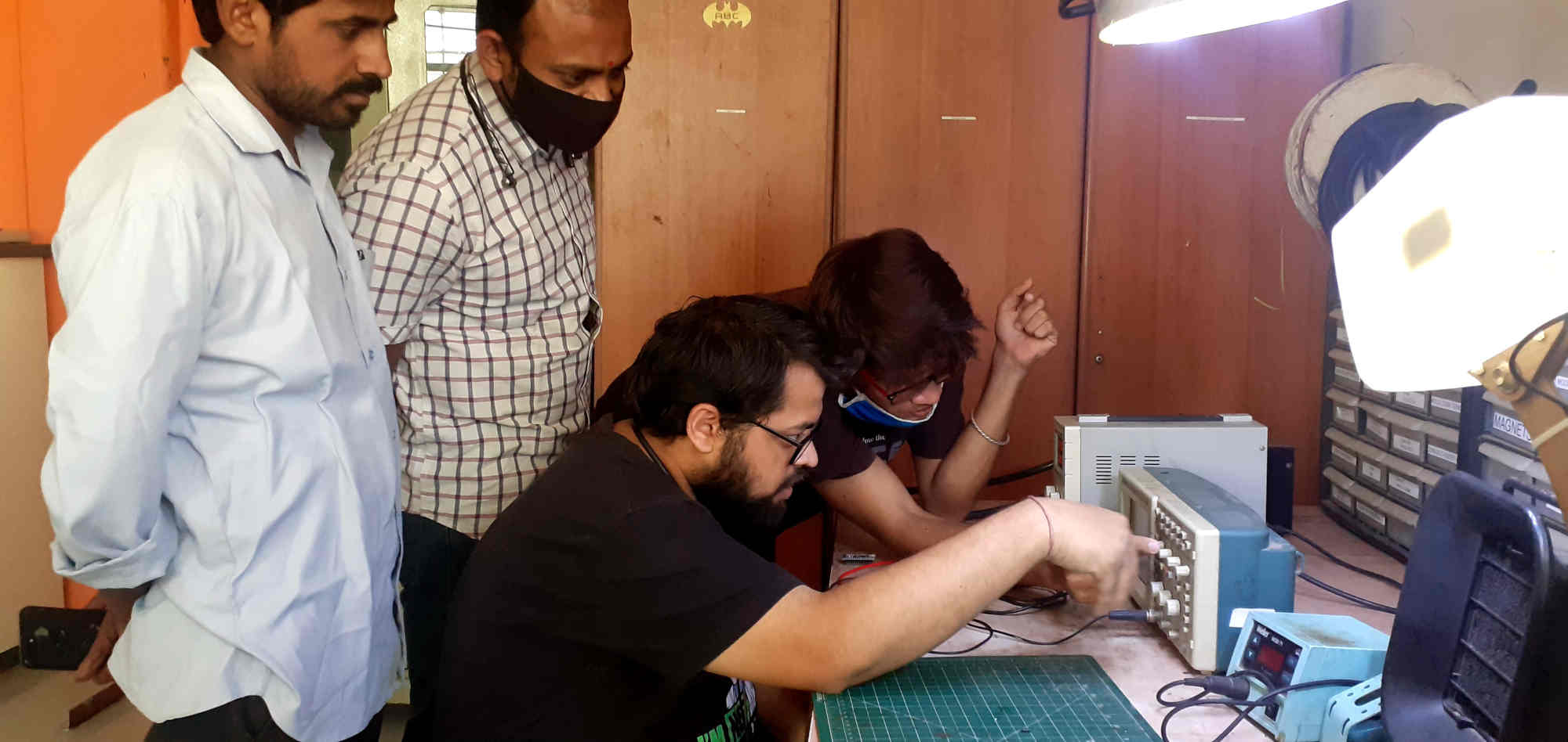
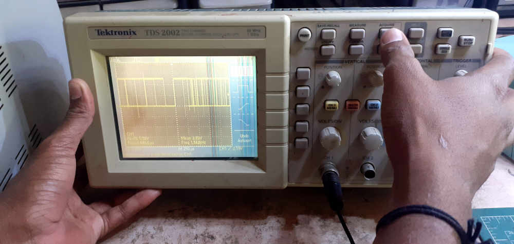
In Group we have test our PCB Hello World Board by applying +5 volt DC voltage to the circuit and analyze the signal through DSO

Our Group member, Mohit Ahuja Uploaded the program of Hello world in his Board, so we have also checked the waveform of this signal
Summary
In this way we have completed this week of group assignment by testing the various Electrical Equipment as well we have test our microcontroller board by appliying voltage, aslo measure it's values with the help of multimeter ,use oscilloscope to check noise of operating voltage and interpret a data signal.