15. Interface and application programming
THIS WEEK CHECKLIST:
- [✓] Linked to the group assignment page
- [✓] Documented your process
- [✓] Explained the UI that you made and how you did it
- [✓] Outlined problems and how you fixed them
- [✓] Included original code (or a screenshot of the app code if that’s not possible)
- [✓] Included a ‘hero shot/video’ of your application running with your board
Group assignment
This time, I work with my groupmates together to compare as many tool options as possible. CLICK HERE for the detailing of group assignment page.
Individual assignment
- Write an application that interfaces a user with an input and/or output device that you made
Once again, this week also is a tough week for me. I have no idea what should I do, so I deide to follow the tutorials to understand about Processing. You may download here.
I search one of the student (MAY EL-DARDIRY, grausted in 2017) in Fab Acadmey was control trun on and trun the LED light. I decide to follow her step to understand how Arduino IDE work with processing for making GUI.
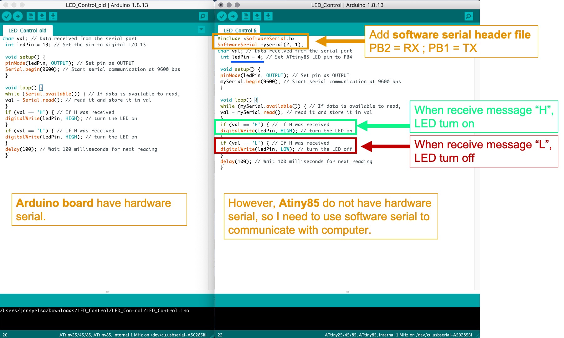
I download the Arduino file for my testing. I find out her Arduino is not work for me because she used Arduino board. However, ATtiny85 do not have hardware serial, so I need to use software serial to communicate with computer. I change PB4 as my LED pin. Also, I set when receive message “H”, LED turn on. On the other hand, when receive message “H”, LED turn on.
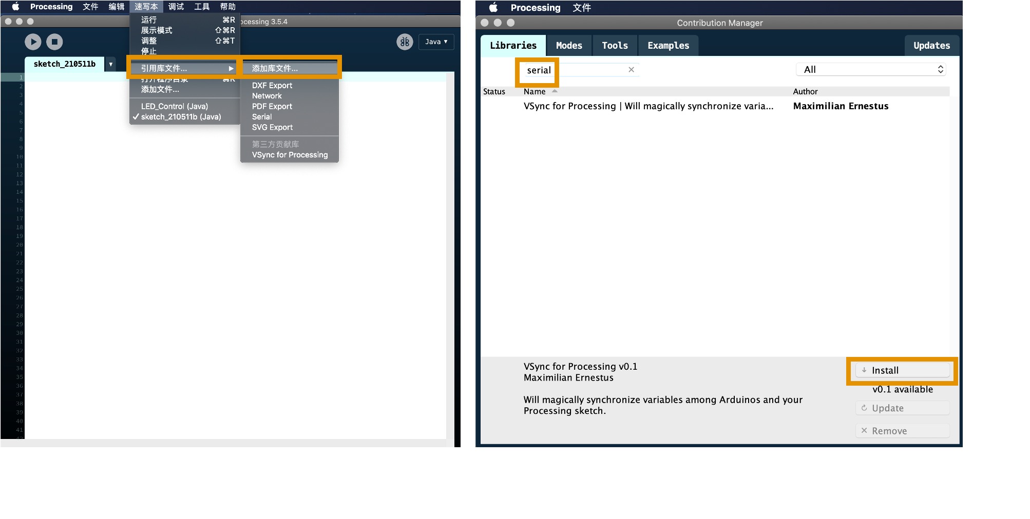
First thing first, I need to install serial for making computer to commuicate with the hardware.
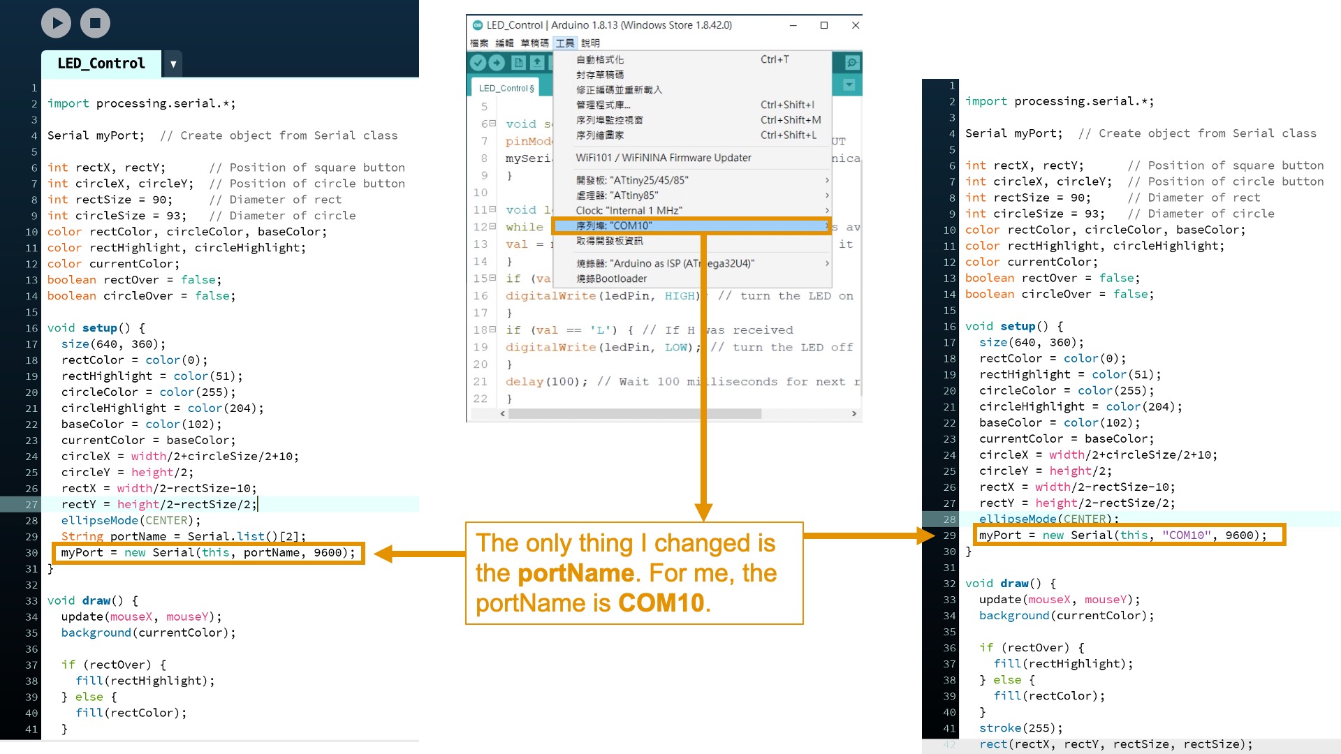
I download the Processing file from MAY EL-DARDIRY. The only thing I changed is the portName. For me, the portName is COM10.
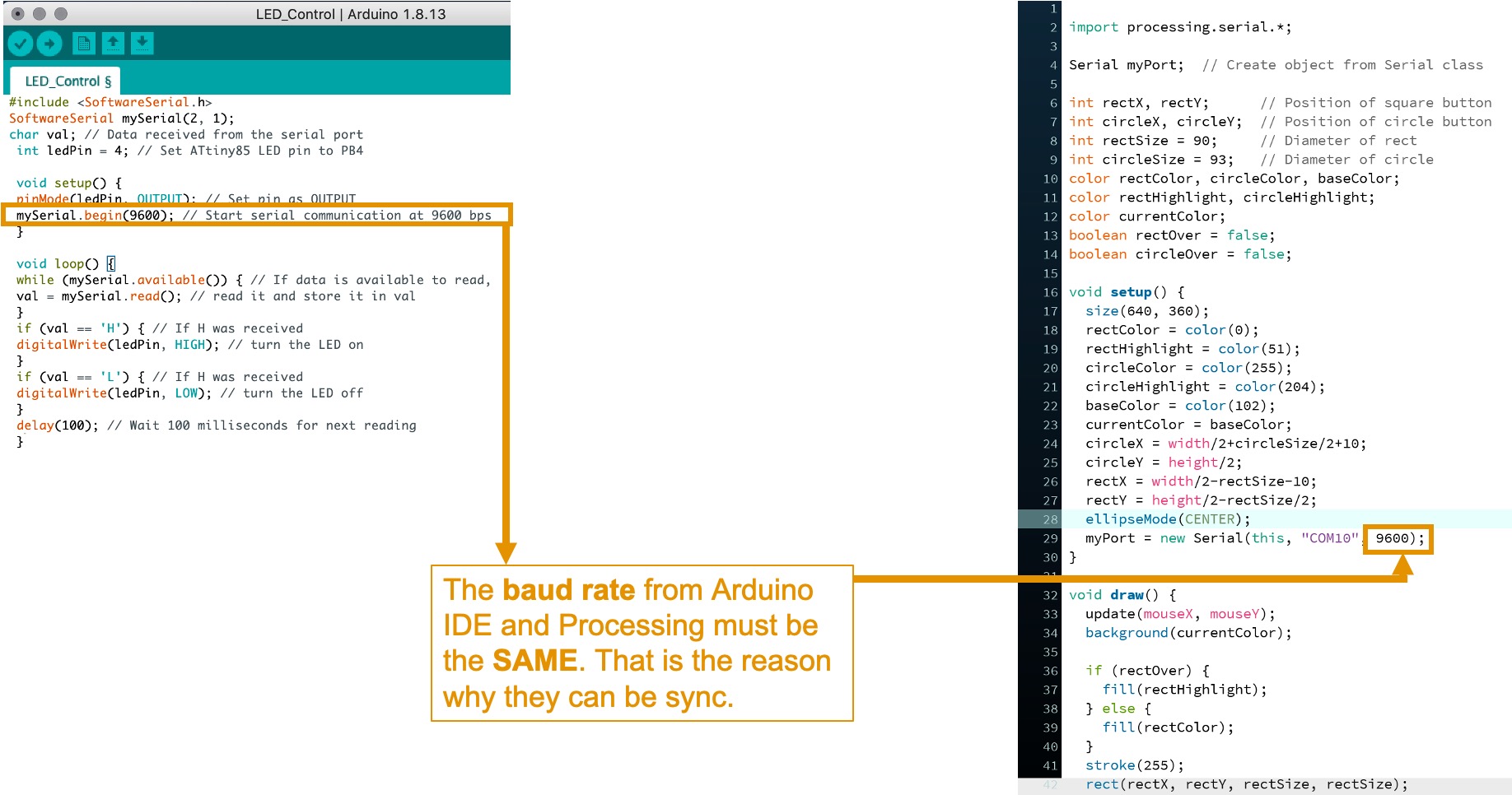
The baud rate from Arduino IDE and Processing must be the SAME. That is the reason why they can be sync.
As you see the video, when I click the square, Processing sending the message “H” though the portname and baud rate (“COM10”, 9600) to my board. Therefore, the Arduino IDE is available to receive message and read message. When the message “H” is match with Processing and Arduino IDE, the LED can be turn on.
On the other hand, when I click the circle, Processing sending the message “L” to ATtiny85. When the message “L” is match with Processing and Arduino IDE, the LED can be turn off.
After adpoting a programm of Arduino IDE to Processing from MAY EL-DARDIRY to make GUI to turn on and turn off LED. I decide use potentiometer in week11 for rotating to control the speed of the crushing cans in my final project. Finally, my board sends the PWM signal let ESC to control the DC motor to crushing the can.
I use the Arduino IDE to rotate the potentiometer the in week11. For the Processing, I draw a circle. The position of the circle base on the x,y coordinate. x changes because the rotation of potentiometer. y just remain unchanged. When the PB3, the pin of potentiometer, receive the data value means the potentiometer have been rotated. The value send to Processing in x vaule, so the the ellipse of x vaule will be change. Finally, the circle move on the x axis from 200 to 455. Last but not least, the baud rate and portName from Arduino IDE and Processing must be the SAME.
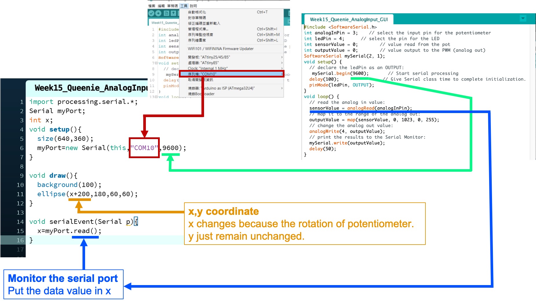
As you see the video, when I rotate the potentiometer, the circle in Processing is moving on the x axis.
That’s all I can do it. Really want to cry!!!!!!!!!!!
Sorce code of Processing
import processing.serial.*;
Serial myPort;
int x;
void setup(){
  size(640,360);
  myPort=new Serial(this,"COM10",9600);
}

void draw(){
  background(100);
  ellipse(x+200,180,60,60);
}

void serialEvent(Serial p){
  x=myPort.read();
}
Sorce code of Arduino IDE
#include <SoftwareSerial.h>
int analogInPin = 3;    // select the input pin for the potentiometer
int ledPin = 4;      // select the pin for the LED
int sensorValue = 0;        // value read from the pot
int outputValue = 0;        // value output to the PWM (analog out)
SoftwareSerial mySerial(2, 1);
void setup() {
  // declare the ledPin as an OUTPUT:
   mySerial.begin(9600);       // Start serial processing
  delay(100);                // Give Serial class time to complete initialization.
  pinMode(ledPin, OUTPUT);
}
void loop() {
  // read the analog in value:
  sensorValue = analogRead(analogInPin);
  // map it to the range of the analog out:
  outputValue = map(sensorValue, 0, 1023, 0, 255);
  // change the analog out value:
  analogWrite(4, outputValue);
  // print the results to the Serial Monitor:
  mySerial.write(outputValue);
  delay(50);
}