9. Embedded programming
THIS WEEK CHECKLIST
- [✓] Linked to the group assignment page
- [✓] Documented what you learned from reading a microcontroller datasheet.
- [✓] Programmed your board
- [✓] escribed the programming process/es you used
- [✓] Included your source code
- [✓] Included a short ‘hero video’ of your board
Group assignment
This time, I work with my groupmates together to compare the performance and development workflows for different microcontroller families. CLICK HERE for the detailing of group assignment page.
Individual assignment
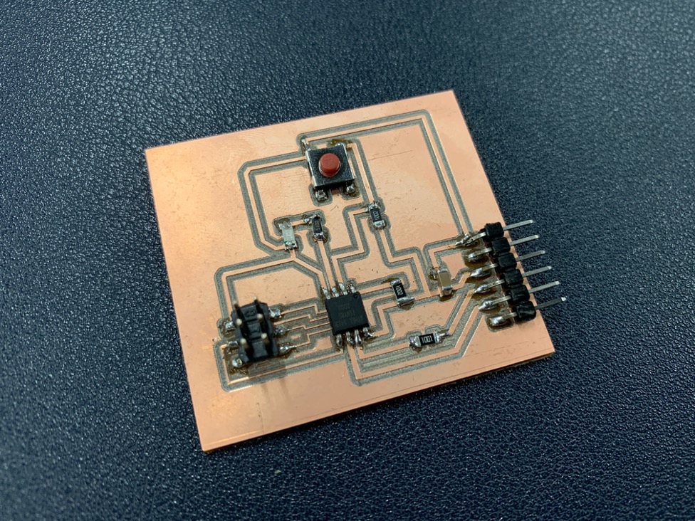
Read the datasheet for the microcontroller you are programming. In week07, I made a board with ATtiny85.
Here is the useful website of ATtiny85.
Datasheet
Summary
Arduino Quick Reference Sheet
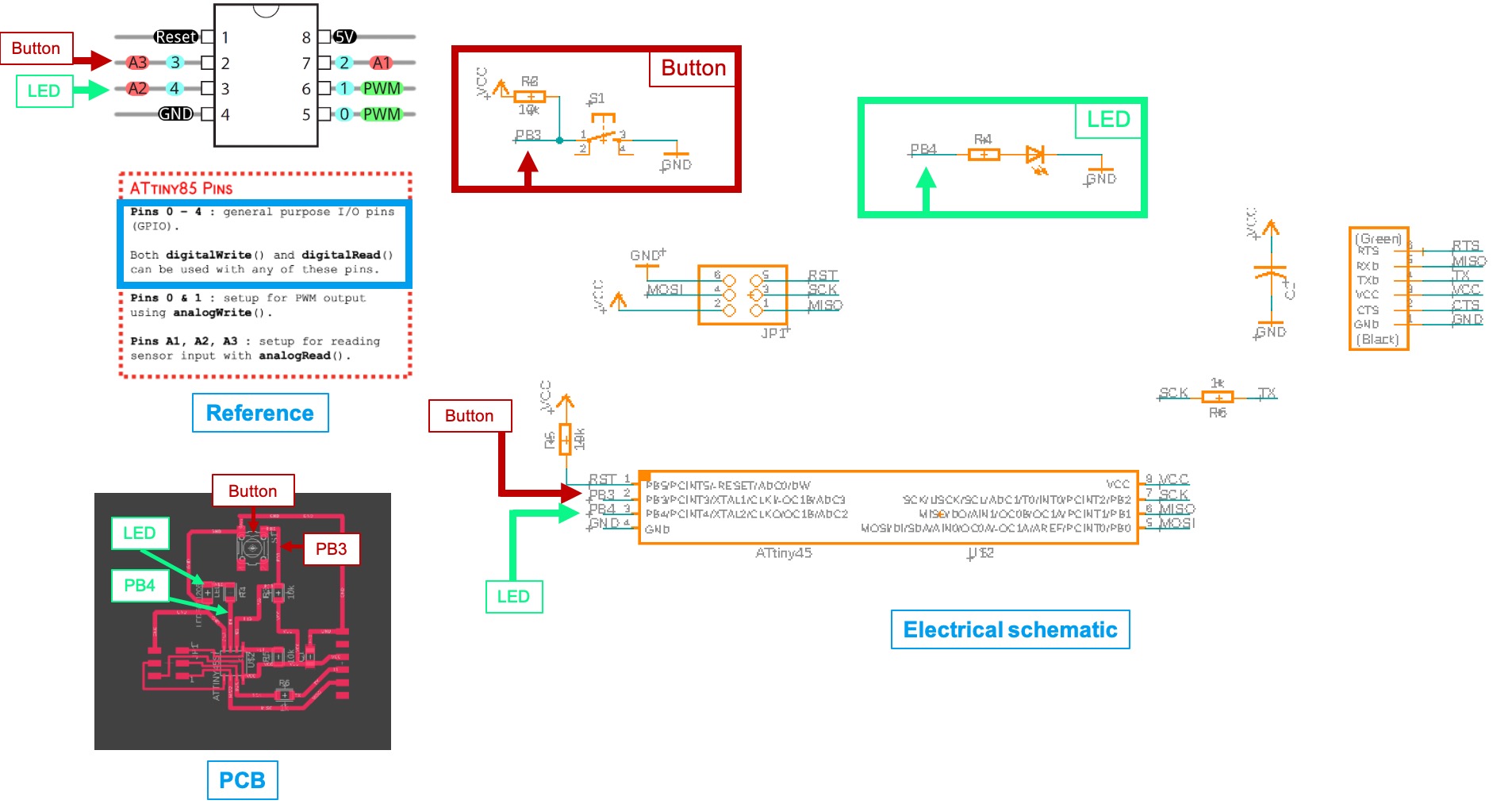
This is the detail of ATtiny85 Pinout Diagram.
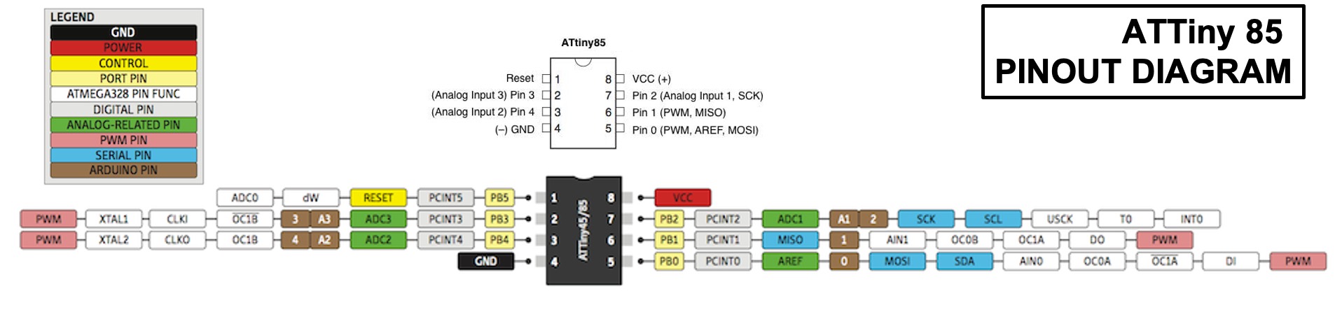
When I design the electrical schematic, I named pin3 as a PB4. I use PB4 connet with LED Light. When you see the the PCB design, you can see PB4 wiil connect with a resistor and LED. After I check with a reference (Arduino Quick Reference Sheet), PB4 is able to digitalWrite() and digitalRead().
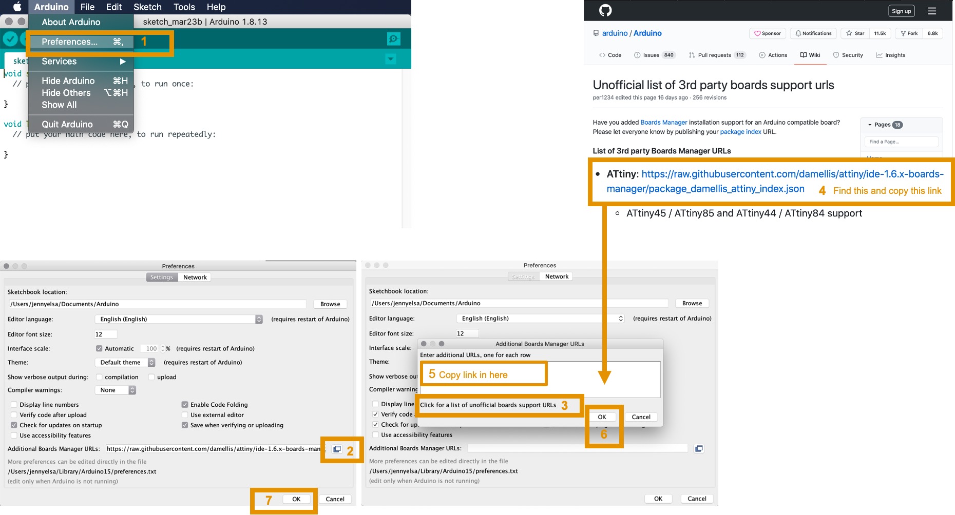
First, going to download Arduino IDE.
For the begining to use Arduino, it don’t install any ATtiny chips. Therefore, it need to download from unofficial list of 3rd party board –> search ATtiny and copy the link into the Additional Boards Manager URLs.
https://raw.githubusercontent.com/damellis/attiny/ide-1.6.x-boards-manager/package_damellis_attiny_index.json
Here is the step.
After that, going to Tool –> Board:”Arduino Uno” –> Boards Manager –> search ATtiny –> click install.

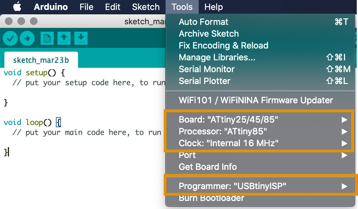
After the installation, select the correct Board, Processor, Clock and Programmer that you use. For me, I select:
Board: ATtiny25/45/85
Processor: ATtiny85
Clock: Internal 16MHz
Programmer: USBtinyISP
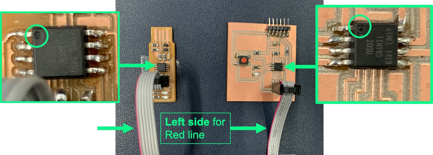
BE CAREFULL!!!
For pluging the cable
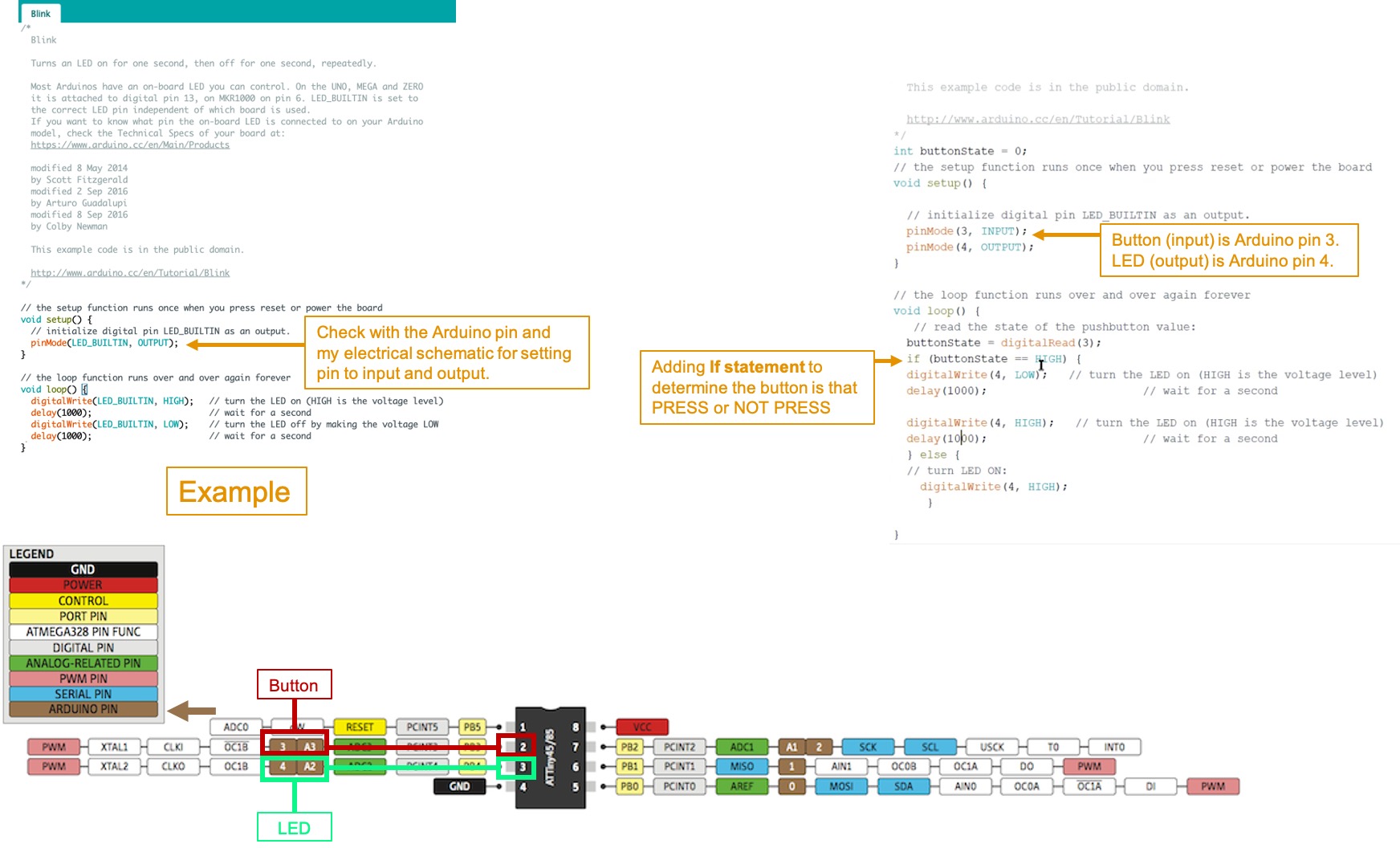
Here is the sorce code for my testing.
int buttonState = 0;
// the setup function runs once when you press reset or power the board
void setup() {

  // initialize digital pin LED_BUILTIN as an output.
  pinMode(3, INPUT);
  pinMode(4, OUTPUT);
}

// the loop function runs over and over again forever
void loop() {
   // read the state of the pushbutton value:
  buttonState = digitalRead(3);
  if (buttonState == HIGH) {
  digitalWrite(4, LOW);   // turn the LED on (HIGH is the voltage level)
  delay(200);                       // wait for a second

  digitalWrite(4, HIGH);   // turn the LED on (HIGH is the voltage level)
  delay(200);                       // wait for a second
  } else {
  // turn LED ON:
    digitalWrite(4, HIGH);
     }

}