14. Networking and communications
For this week, I have learnt on Networking and communications
The Networking and Communications area focuses on the design and performance evaluation of communication systems and data networks of all kinds, including wireless/cellular, optical, mobile, the Internet and so on.
During the evolution of technology, in the field of single-chip microcontrollers, one of the serial interfaces, I2C, have become very common.

The Characheristics of I2C are:
-
the synchronous transmission interface, which is mainly used between the CPU and peripheral chips.
-
to reduce the number of pins between the CPU and peripheral chips for the main purpose of I2C design .
-
only two wires which are necessary and obviously different from the dozens of wires commonly used in the early parallel bus.

The I2C bus wiring is very simple, with only two signal lines:
1. data line (SDA, Serial Data Line)
2. clock line (SCL, Serial Clock Line)
All I2C devices, whether master or slave, are connected with these two pins which are internal switches.
Case 1
When it is turned on, it is grounded logic low level (Low).
Case 2
When it is not turned on, it is like a broken wire floating.However, the I2C Bus must be added with a boost resistor Rp onto both SDA and SCL. Then floating The state changes to a high logic level (High).
For this week, I have worked on:
Group Assignment:
We have sent a message between two projects. If you have interest, you can CLICK HERE to know more about the details.
Individual Assignment:
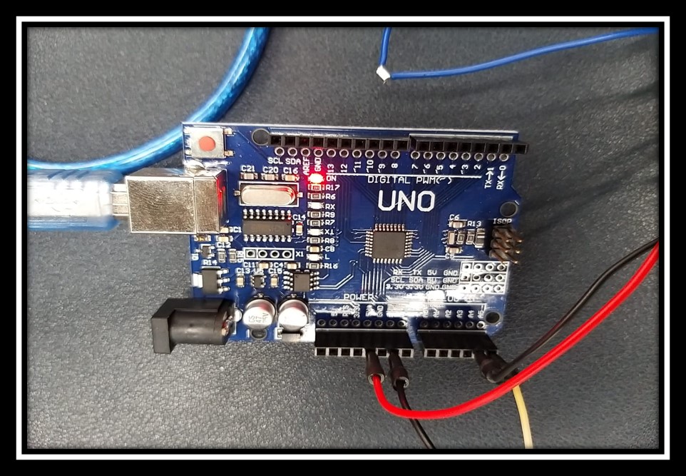
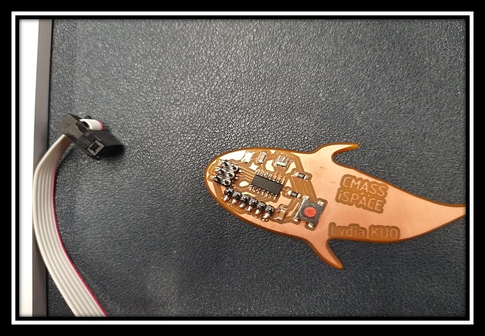
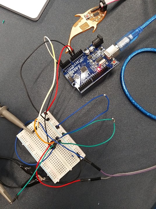
This is my prototype of connecting Arduino UNO as the Master with my previous PCB, ATtiny44 as the Slave for this week. I would like to send the signal for each second and the LED would follow the signal to blank

Arduino UNO as the I2C Master
ATtiny44 as the I2C Nodes
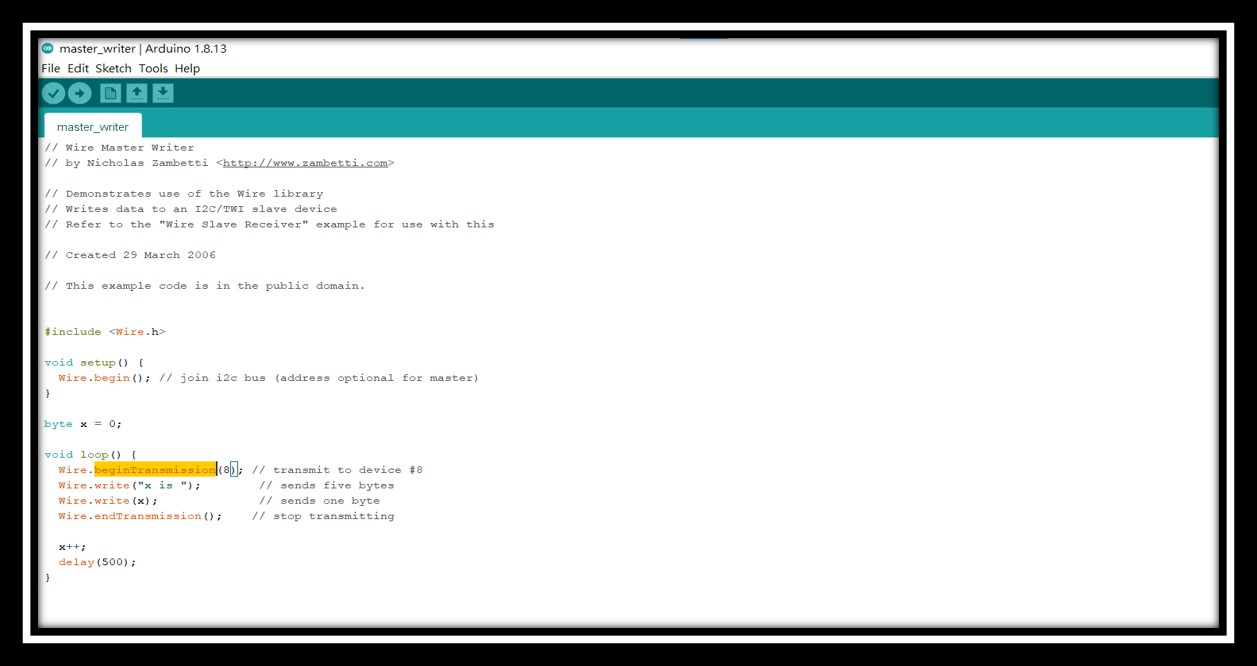
I have found the example from the Arduino library for the master_writer. The function of the master_writer sent simple message to one of the nodes.
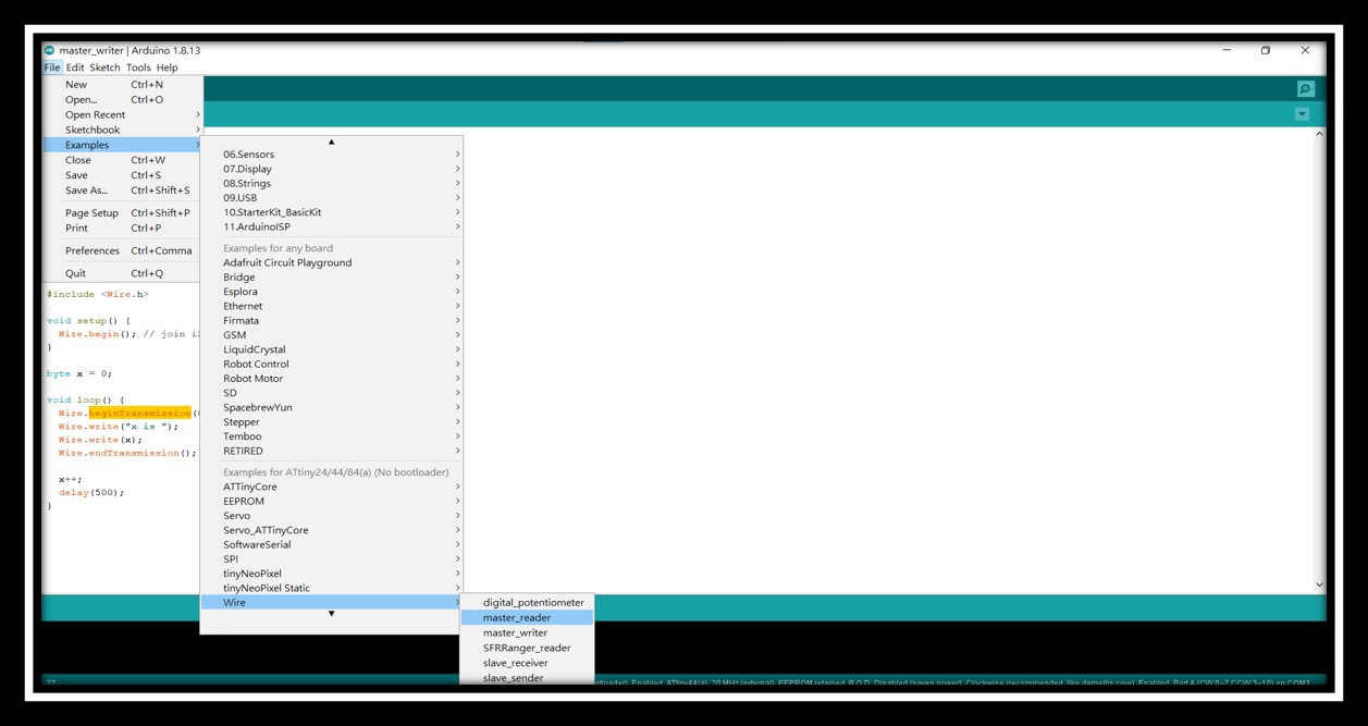
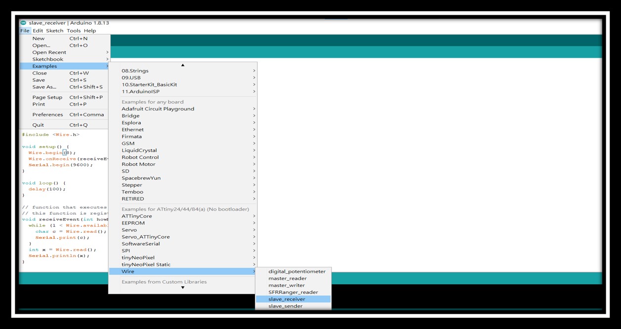
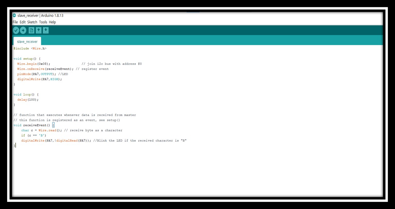
I have also found the example from the Arduino library for the node_receiver. The function of the node_receiver received one-byte message from the master node. If the received message was character B, then turn on the LED connected PA7.
Smart Scope is a a digitial oscilloscope for connecting between the devices and the computer. It used the computer as an interface to analyse the output waveform of the device.
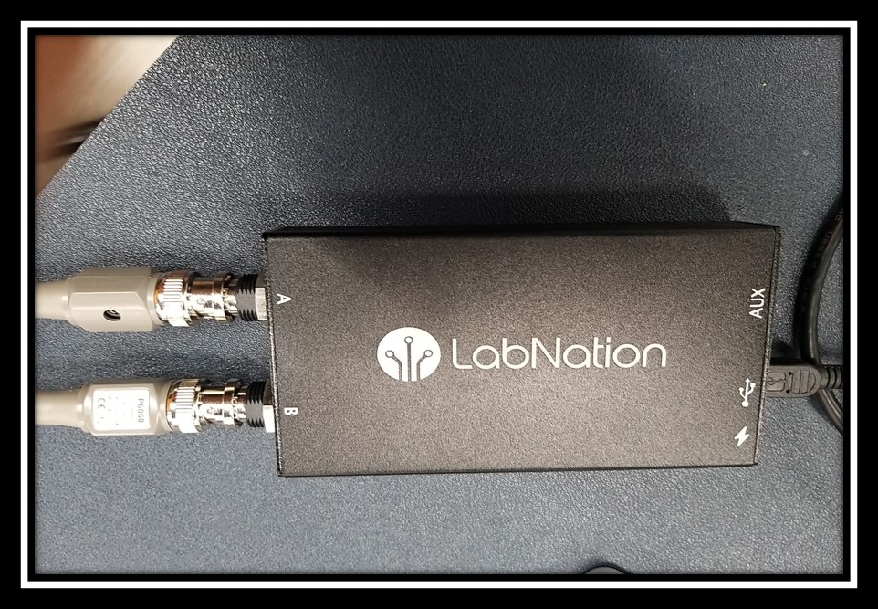
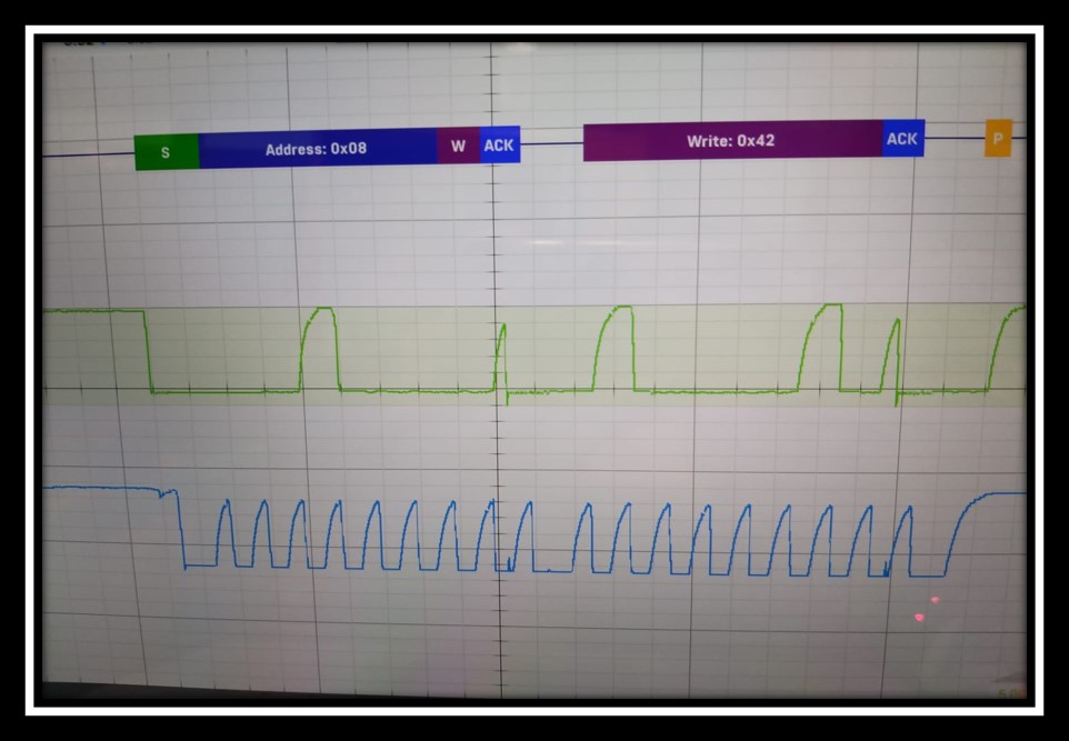
Oscilloscope recognized the I2C protocol and decoded the message on the bus.
The following video showed two boards are synchonized via I2C.
For this week, I had faced a connection problem was that signals were received unstable. I have tried an error long time to find that I forget to connect the pull up resistors. After connected two 120ohm resistors between the signal lines and VCC, the problem had been solved as below.
***Source File for main writer
***Source File for node receiver