11. Input devices
For this week, I have worked on:
Group Assignment:
We have probed, as the meaning of measured, oberserved or monitored signals with test probes, an input device’s analog and digital signals by a test probe which is a physical device. This device is used to connect electronic test equipment to a device under test (DUT).
If you have interest, you can CLICK HERE to know more about the details. Some main points are mentioned below.
Individual assignment:
For my final project, I would like to design an ideal device for aquaponic system, which can be placed anywhere, including appropriate growth environment for fishes and herbs. The following feature which is one of the view points in our school.

If we want to set up a healthy aquaponic environment for the growth of fishes, we should be aware of the presence of concentration of toxic chemicals, such as ammonia/ammonium ions. This is because these chemicals can damage the tissuesin the fishes’ gills. 10 Basic Fish Health Tips to Keep Aquarium Healthy can be found as follows:
Therefore, some sensors will be added in my final project for measurement of the presence of different chemicals. At this week, Add a Colour Sensor to the microcontroller board that I have designed in Week 7 and read it as following steps.
Measurement of Concentration of Ammonia or Ammonium ions in the Aquaponic System in our School
Step 1 Search for Related References
Our fishes may suffer permanent gill damage which could affect their respiration as well as their ability to expel excess ammonia from the body.

For traditional way, indicating ammonium ions in the solution is added with any alkaline to produce ammonia that shows the presence of this harm chemicals. However, this must be done in the fumecupboard in the laboratory and cannot be applied to the aquaponic system easily.
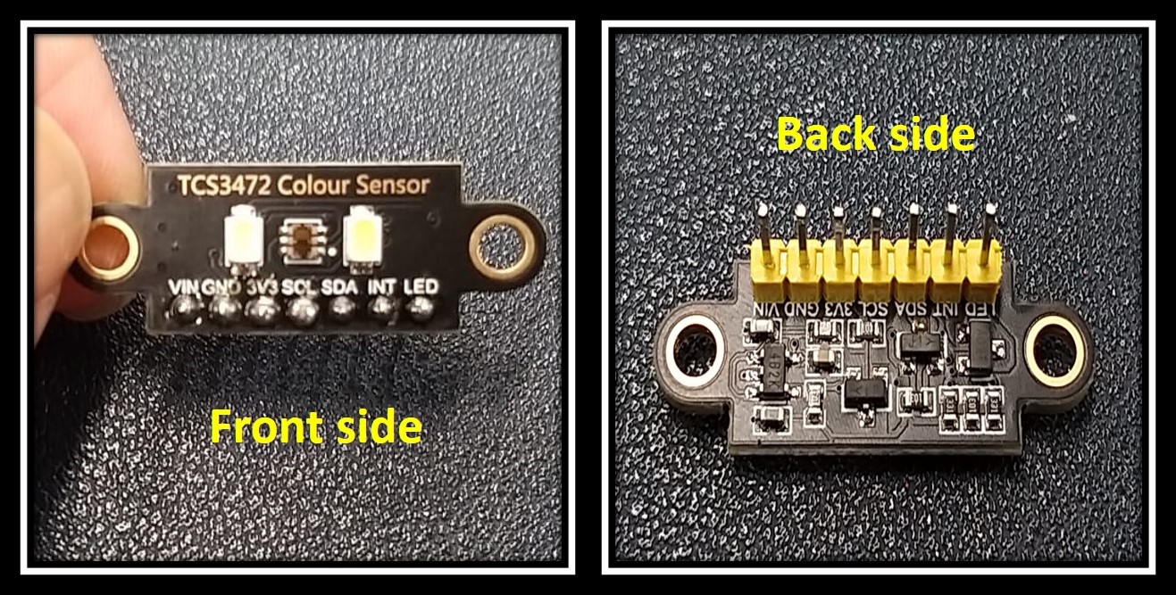
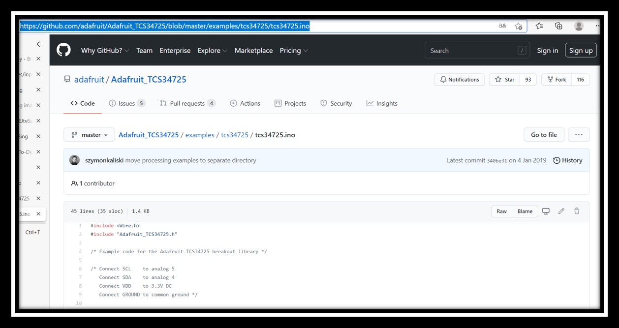
Step 2 Choose Colour Sensor TCS34725
Therefore, colour sensor TCS34725 is chosen for detecting the colour change of mixing the testing agents with the water sample and some known centration of ammonia water to indicate the safety for fishes’ living.
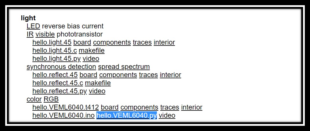
Python user interface was used from hello.VEML6040 as references and protocol to communicate with GUI.
At this time, TCS34725 Colour Sensor was used for Red, Blue, Green colour analysis and white brightness.
Arduino UNO was used to test for the functions of light sensor as following workflow.
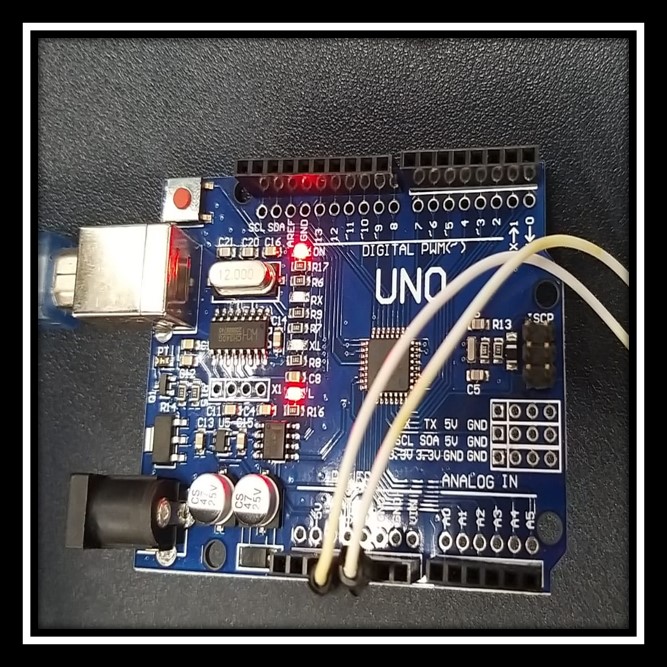
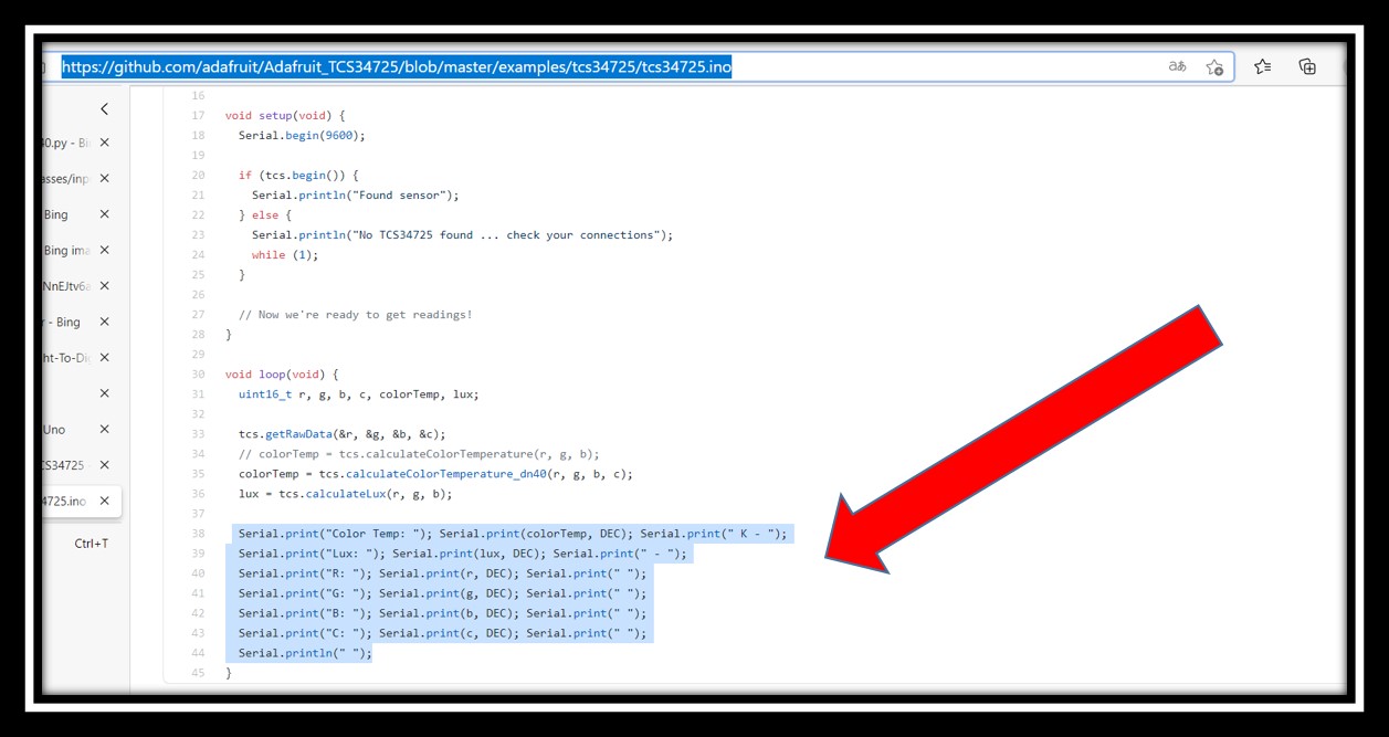
- Install Library Adafruit TCS34725
- Change serial output format
Adjust numbers and words to adapt the interface.

The interface was shown in the computer as follows:

-
Do the experiment for testing concentration of ammonia/ammonium solution
-
Prepare different testing solutions with 3 testing agents from the kit test for ammonia/ammonium solution. These solution were included 1M Ammonia water, 0.5M Ammonia water, Distilled Water and the Water Sample from our Aquaponic System. The procedures of mixing different testing agents were shown in he following video.

Result Data for 1M Ammonia Water

Result Data for 0.5M Ammonia Water

Test solution colour of the solution contained red, green, blue rays could be detected by color sensor separately. The length of the colour bar can be indicated the concentration of ammonia in the solution. The higher the ammonia concentration, the higher the colour intensity which was red, green or blue ray.
I have found that there were great errors for this measurement environment because :
-
Surrounding Light was affected the light receiving from light sensor.
-
The apparatus should be changed to another shape for the contact of the sensor.

Two more modifications should be done for getting more accurate results for measurement of ammonia/ammonium concentration by my target board, ATtiny44 PCB board which was made in week 7.
-
Code for arduino should be adapted to the target board. target.

-
The flask, which was easily shaked all inside solutions, should be replaced by another translucent and smaller bottle. Colour Sensor should be placed vertically and concentrated to detect the colour from the sample as much as it can.

- An extra test sample chamber should be designed and printed by 3D printing machine, for ensuring all colour change should be detected by light sensor without any interference from the environment.

At this time, 3D printing machine - RAISE3D was used for making test sample chamber.
Some special features for this 3D print design of sample test chamber:
- The whole chamber was divided into two parts and placed onto a tiny horizontal plane. Therefore, two parts can be printed altogether at once.
- There was some space between the inner and outer wall of the chamber. This made sure that the chamber could be kept in shape with less printing material used.
Colour Sensor TCS34725 was fixed onto the outer wall of the sample test chamber that the side of sensor was faced inside. The translucent bottle with testing sample was placed inside the chamber and covered with the upper part of the chamber. Since the sensor was placed inside the chamber and would not be influenced by any factor from the outside environment.
File download
***code download here tcs34725.ino