
Input Devices
Sensors: The senses of the microcontroller!
Can you imagine giving your ATtiny1614 board the ability to sense the world around it? That's what we'll do here. With a photoresistor, I'll teach it to detect light as if it had “eyes”, and with sound sensors, I'll make it “listen” and display its findings on the Arduino IDE serial monitor. It's like giving your microcontroller super senses so that it's not just sitting there doing boring calculations, but interacting with the environment like all action protagonist! 🎉
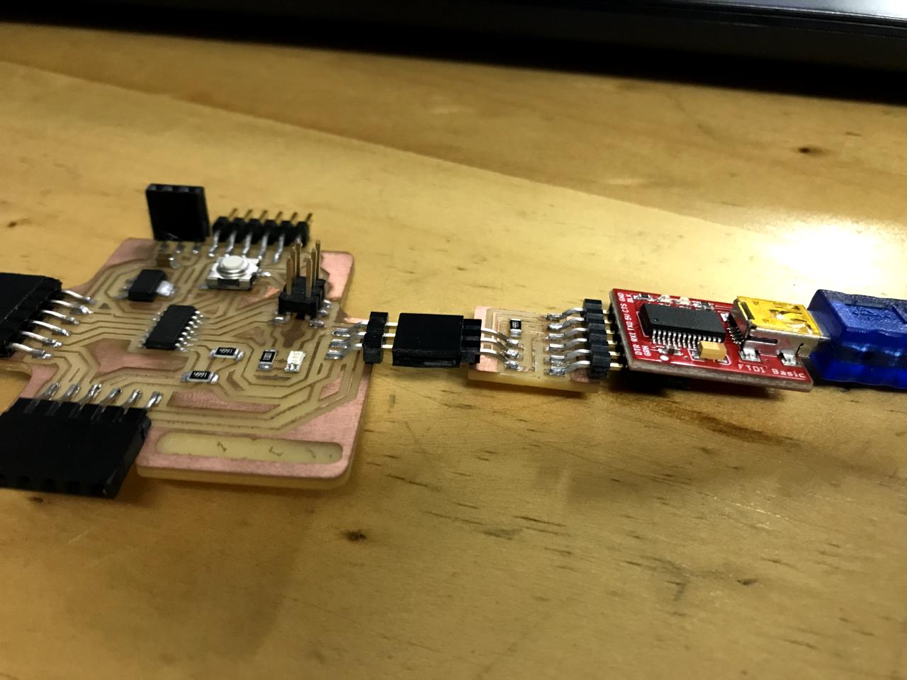
Let's work with my board again
Week 10 Assignment
GroupTask
Together with Mayra,we did the group exercise and the explorations, this week we first tested the input sensors with an Arduino Mega, to see how a signal can be read as data. In this case we practiced with an ultrasonic sensor.
Readingsignals
This system is a distance measurement project based on a HC-SR04 ultrasonic sensor and an Arduino Mega board, mounted on a breadboard.
Main components
- This is the “brain” of the system. The Arduino Mega receives the signals from the ultrasonic sensor, processes them and can display the results or use them to control other components.
- This sensor measures distance using ultrasonic waves. It has two “eyes”:
Trigger (emitter): Sends an ultrasonic pulse.
Echo (receiver): Receives the bounced pulse when it hits an object.
The time difference between sending and receiving the pulse allows the distance to the object to be calculated.
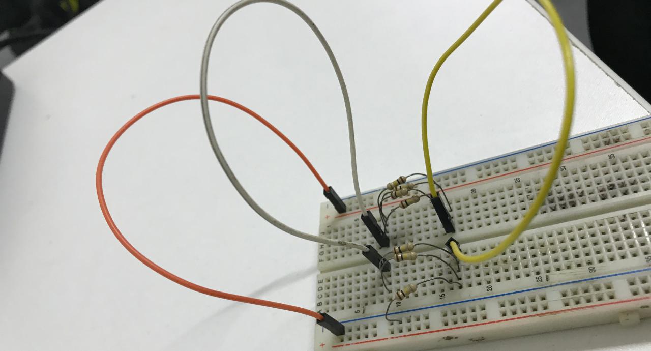
Connecting
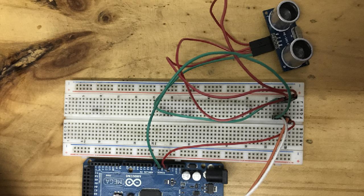
Ultrasonic sensor hc-sr04
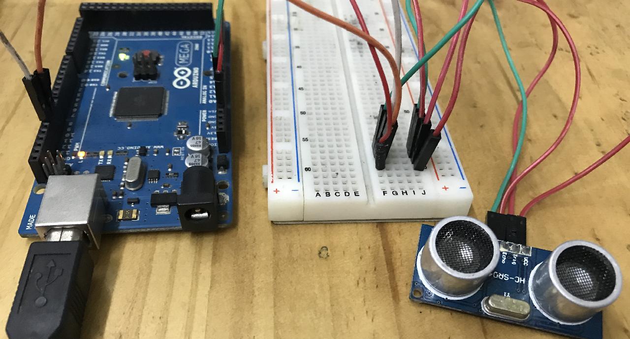
Practicing with Arduino Mega and ultrasonic sensor
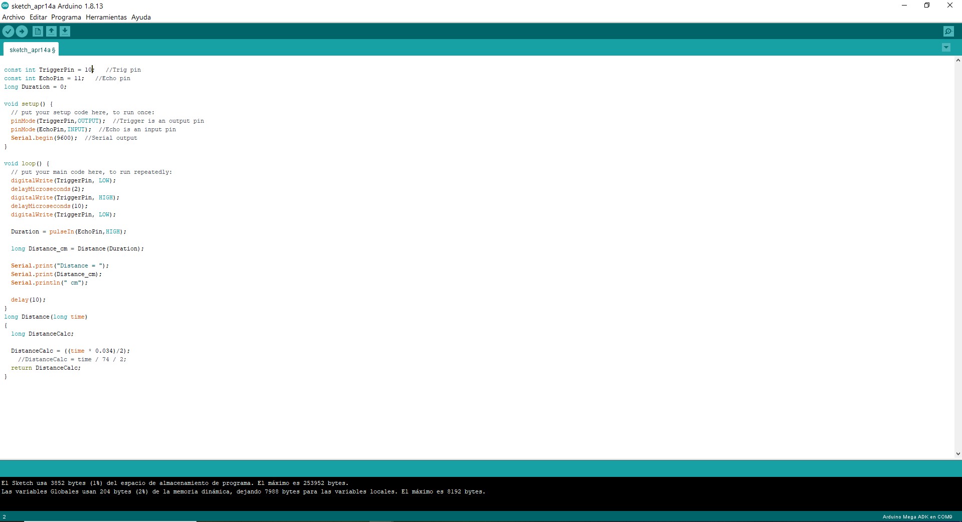
Code Arduino IDE
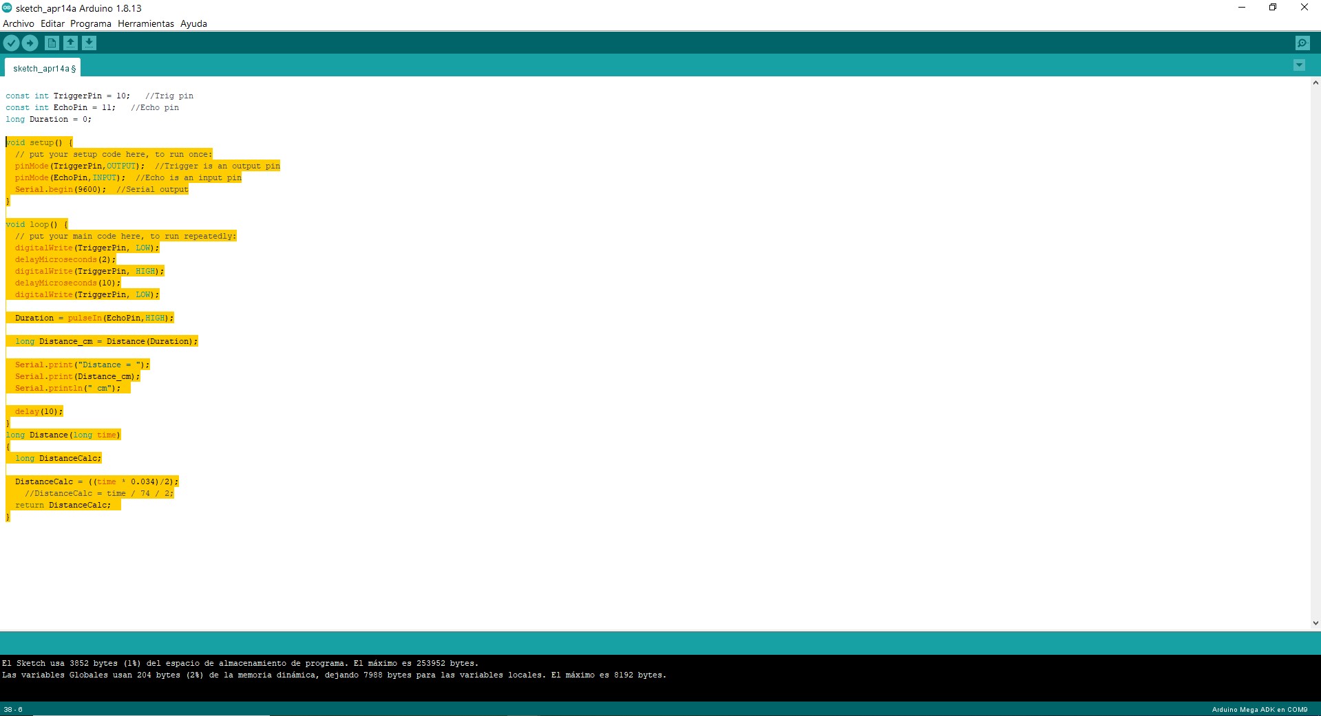
Code
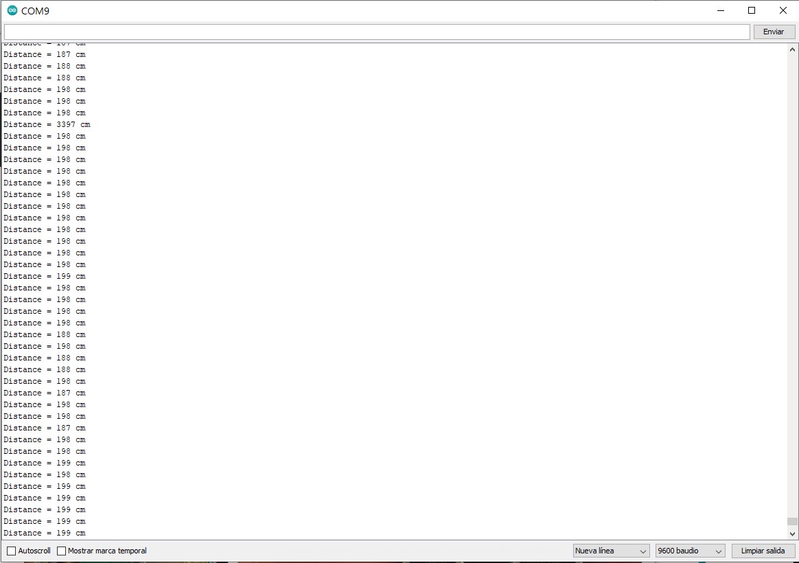
Serial monitor, reading the signal as distance
Reading the signal as distance
IndividualTask
Lorem ipsum dolor sit amet plantilla consectetur adipisicing elit. Debitis, reprehenderit dolores ad natus recusandae enim aut quod dolor facilis commodi ipsum sed corrupti deserunt quis earum perspiciatis rerum repellat sunt? plantilla link
First try 😅
My first exercise is to use a photoresistor as input. In this case, you will use the photoresistor to measure the light hitting it. What I did was to convert that reading into something visual, like turning on an LED if the light goes below a certain level (for example, a sort of “night alarm”). Fotorresistencia CDS 5 mm Resistencia: 100 ohm - 2 Mohm LDR 5516
Main components:
- Photoresistor (LDR) CDS 5 mm Resistor: 100 ohm connected to an analog pin of the ATtiny1614
- A 10K Ohms resistor 1/4w to complete the circuit.
- An integrated on-board LED to indicate the light level.
What happens:
- The photoresistor senses how much light there is.
- A 10K Ohms resistor 1/4w ohm resistor10k ohm resistor to complete the circuit.
- LED on or off (or displays the value on the Serial Monitor if you have a connection).
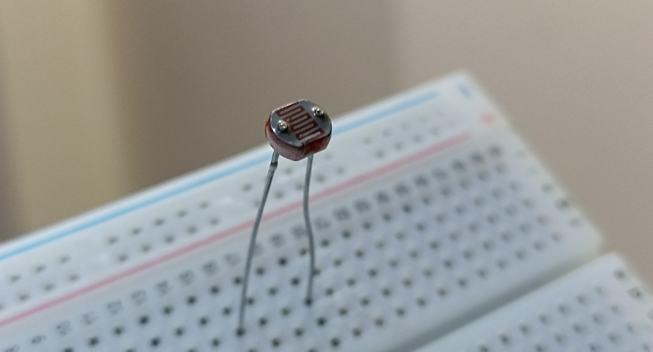
Photoresistor (LDR)
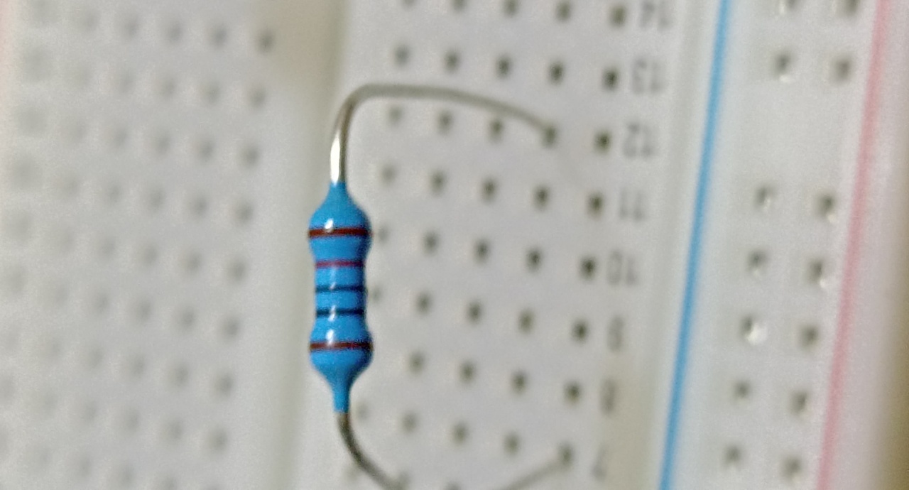
10K Ohms resistor 1/4w
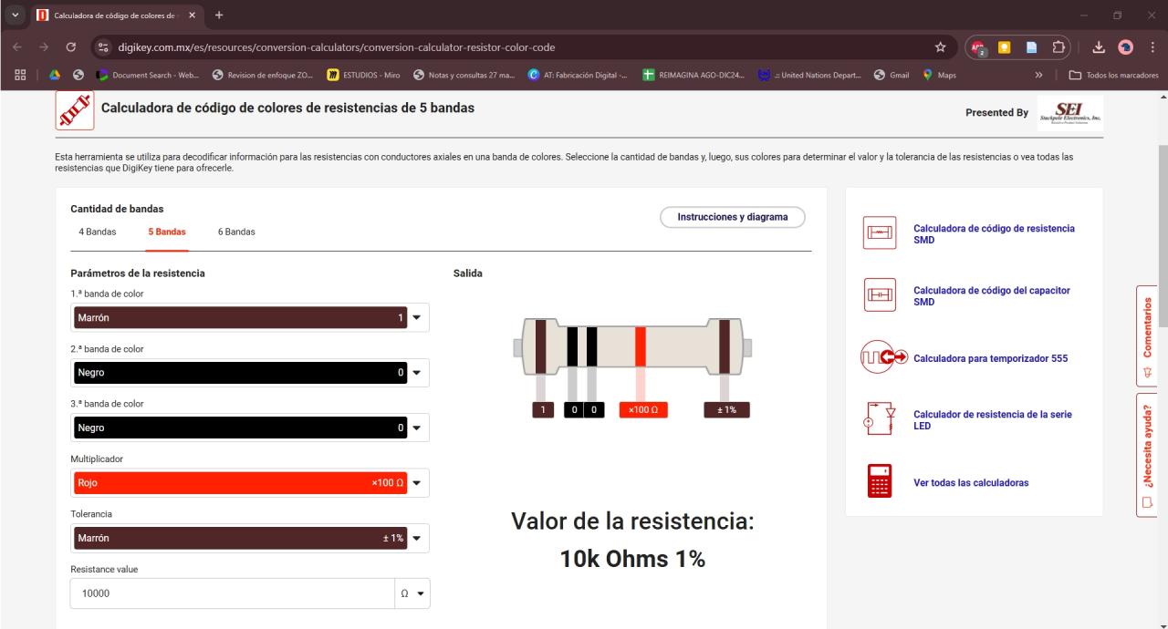
Reading the value of resistors by color
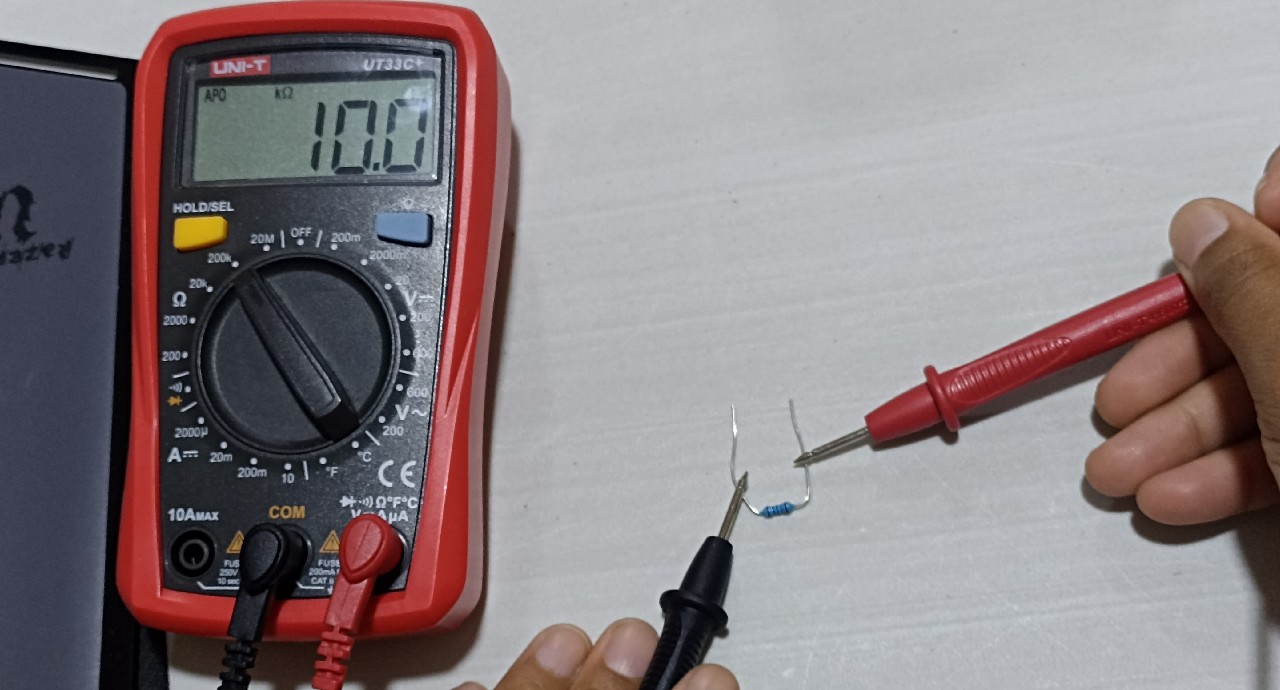
Measuring the value with the multimeter
In this “resistor color calculator” from Digikey you can put the colors of your resistor and it helps you to find the value is the maximum. I encourage you to try it.
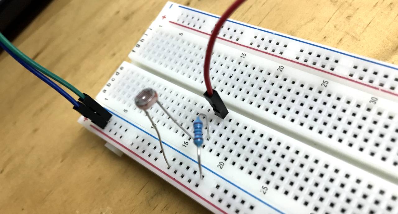
The photoresistor

The system
        const int LDR = 0;
        const int led = 8;

        int lightCal;
        int lightVal;


        void setup()
        {
            // We'll set up the LED pin to be an output.
            pinMode(led, OUTPUT);
            lightCal = analogRead(LDR);

        }


        void loop()
        {

            lightVal = analogRead(LDR);


            if (lightVal < lightCal - 50)
            {
            digitalWrite(8, HIGH);
            }

            else
            {
            digitalWrite(8, LOW);
            }

        }
Arduino IDE Code Photoresistor + Led
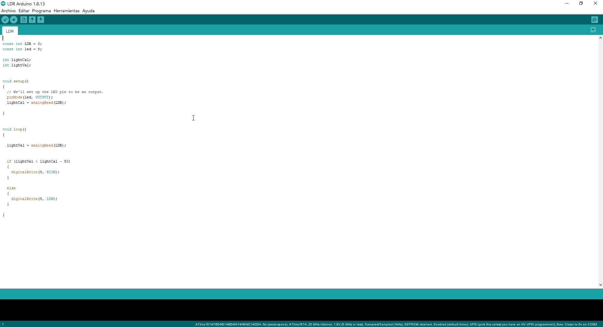
Photoresistor LDR Program
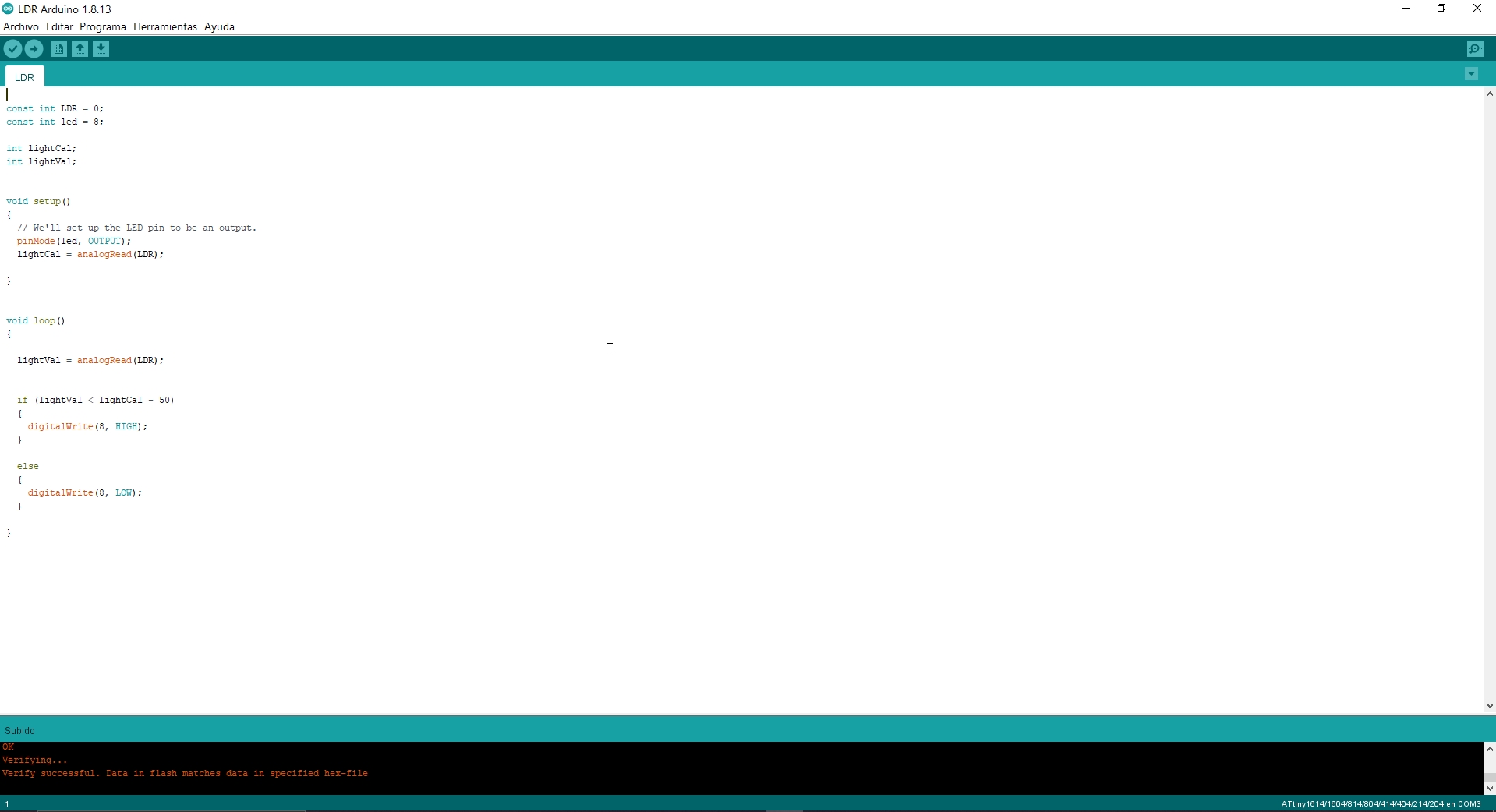
Photoresistor LDR Program uploaded.
Input ready!
Second try 😅
In this second exercise I will test the sound and LCD sensors, in my case before this assingment was solved much earlier than embedded programming. So this exercise was done first. Here I will use the sound sensors to pick up noise and display the detected decibel levels on the LCD. This exercise helps me understand how to handle more complex inputs and visualize them.
Main components:
- 1 Sound sensors KY-037 connected to analog pins of the ATtiny1614.
- My board
- The sensors detect the sound level (in the form of voltage).
- The microcontroller reads the highest (peak) value.
- That value is converted to dB and displayed on the Serial Monitor screen.
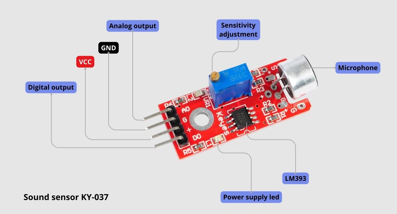
Sound sensor KY - 037
            /* Código para mostrar valor em dB */
            const int Sensor1AI = 0; //Sensor Analogo Interno, Entrada A0
            const int PinoDigital1 = 1;
            //#include
            //SoftwareSerial mySerial(2,5);

            //int Estado = 0;
            int ValorSensor1 = 0;
            int valorMayor1 = 0;
            float volt1 = 0;
            int dB1 = 0;


            int cont = 0;
            /*
            Board I2C / TWI pins
            Uno       =   A4 (SDA), A5 (SCL)
            */


            void setup() {

            Serial.begin(115200);

            }
            void loop()
            {


            while(cont < 10000)
            {
            ValorSensor1 = analogRead(Sensor1AI);
            if(ValorSensor1 > valorMayor1)
            {
            valorMayor1 = ValorSensor1;
            }

            cont++;
            }
            cont = 0;
            volt1 = valorMayor1/1023.0*4.53;
            dB1 = 87.1*volt1 - 75,4;
            if(dB1 < 0)
            {
            dB1 = 0;
            }

            Serial.print("DB: ");
            Serial.println(dB1);

            valorMayor1 = 0;

            delay(100);

            }
Arduino IDE Code Sound sensors KY-037
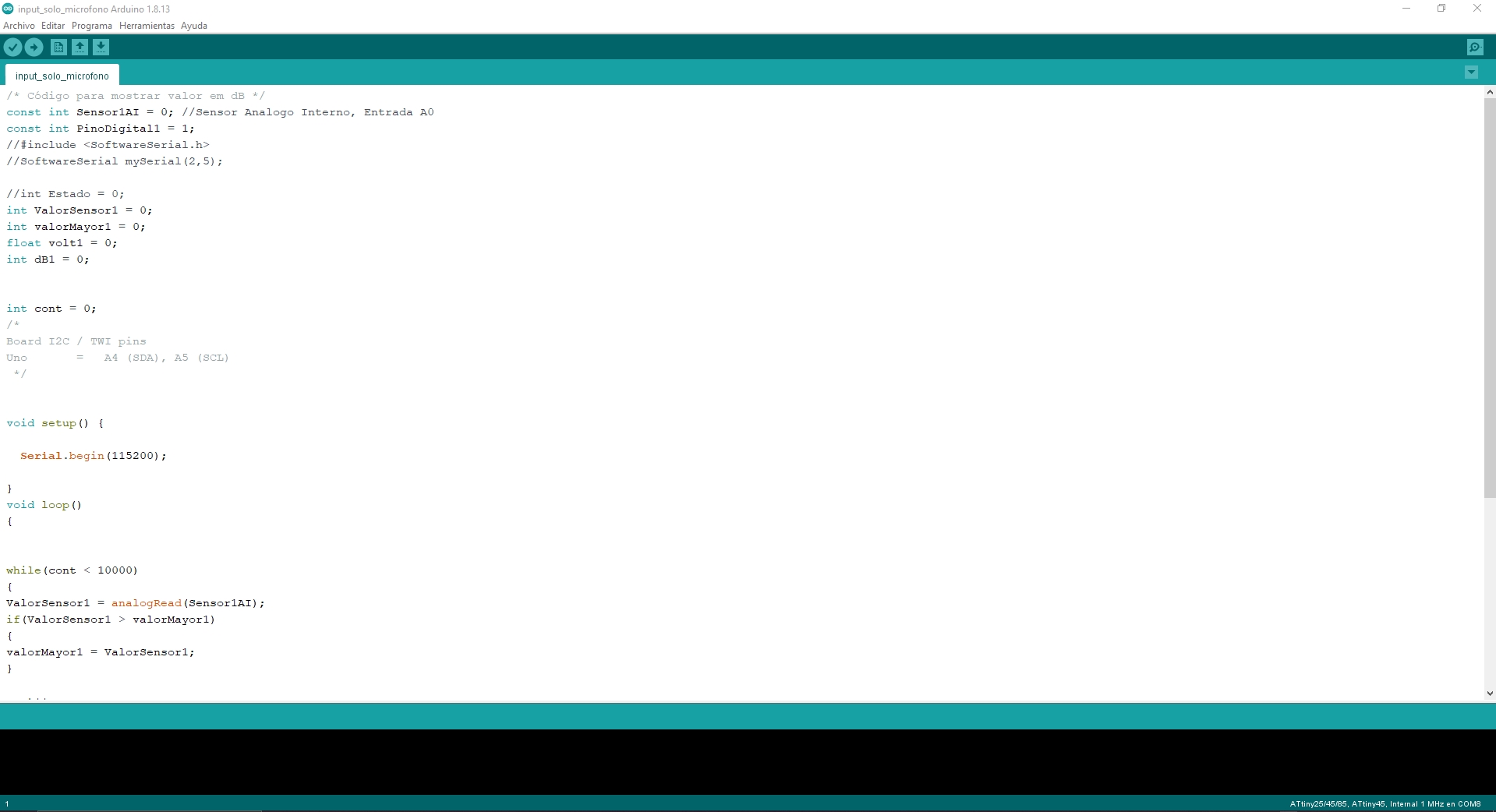
Arduino IDE Code
Sound sensor input ready!
AboutLearning
- I used a photoresistor to measure the amount of light. This small component changes its resistance depending on the light it receives. By connecting it to an analog pin, the microcontroller receives values (0-1023) that represent how much light there is. With a little bit of code, I was able to convert those values into an action, such as turning on an LED when the light gets low. I've already made a basic system that “sees” darkness!
- Then I moved on to the sound sensors, which detect noises and convert them into electrical signals. The microcontroller reads these signals as analog values (just as with the photoresistor). Using a formula to convert those values into decibels (dB), I was able to display on an Serial monitor screen how loud the sound was. It's like having a digital ear that tells me in real time how loud the environment is.
My Veredictfrom what I learned
- I learned that sensors are the key to connecting the physical world with the digital world. The microcontroller doesn't see or hear on its own, but with input sensors, it can pick up light, sound, temperature, motion... you name it. And the best part is that you can control it all with a few lines of code!
- This week I discovered that with sensors as input and microcontrollers as brains, I can build systems that sense the world and act accordingly. it's like giving super senses to my electronic projects! 🚀