7. Electronics design
This week we had to create our own designed PCB and of course manufacture it.
The idea
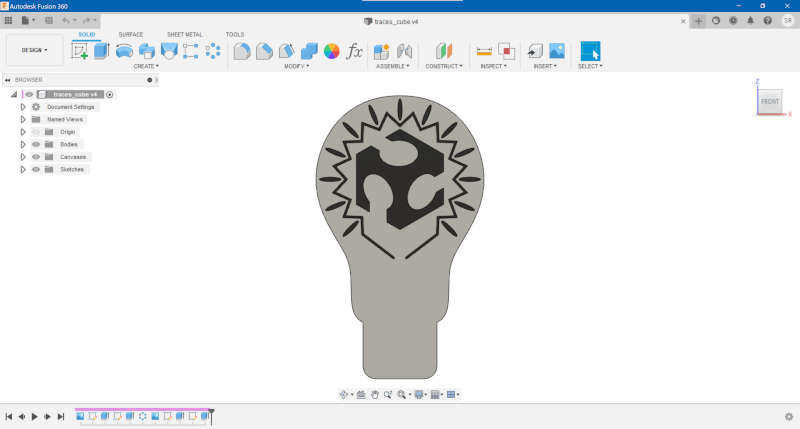
To begin, I need to think about what I will do. After some reflection, the idea is to do a mix between two symbols. The first one is of course the fablab’s symbol, that I will put in the center of the second one that expresses having a great idea, the eureka’s bulb. Because we have a lot of these great ideas in fablabs.
As for the board, I will connect a button and three LEDs to an Attiny412. I’ll also try to make the headers (UPDI and FTDI) look like the screw of the bulb.
The design
Being a full-fledged user of Fusion360, I wanted to experiment with its new electronics workspace.
So I begin to draw some sketches of my bulb hoping to be able to push it to the PCB design later.
My first idea was to put my three LEDs in series, at that time I wasn’t thinking with an electrical point of view and only wanted to draw something “pretty”. But then speaking with my colleague, he asked me if I checked if it was possible. So I did the math, 3 Leds which each need 3V will need 9V in total if put in series (really hard math). However the board will only have 5V, so I changed my first design and put the LEDs in parallel which should only need 3V. The picture below was my first idea that isn’t possible :

Then I went to the electronics workspace, before beginning the design of my PCB I checked the import possibilities but nothing is working with what I want to do. Apparently the only solution is to import a picture of my traces in BMP format. The only shape that can be pushed between 3D design and electronics is the outside dimensions of my board. And one more thing BMP imports is buggy and doesn’t work, so I’m back in Eagle.
The first thing to do is to add the necessary libraries to C:\Users\”your_name”\Documents\EAGLE\libraries :
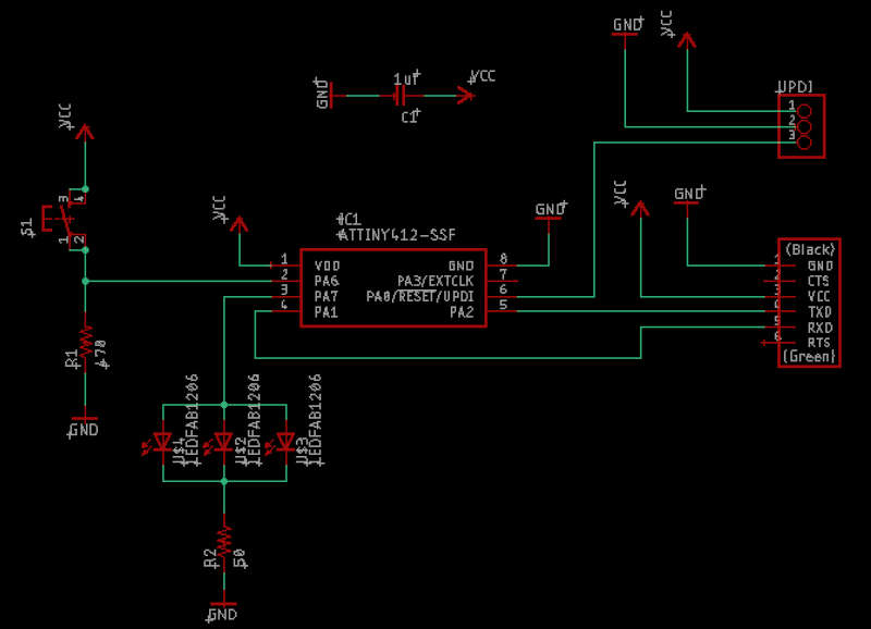
After that, we are ready to do the schematic. The components used in my board are :
-
Attiny412
-
LEDFAB1206
-
CONN_03SMD_RA_MALE
-
CONN_06_FTDI-SMD-HEADER
-
SW_SWITCH_TACTILE_6MM
-
R1206FAB
-
CAP_UNPOLARIZEDFAB
The next step is to connect everything together :
When you finish your schematic, then you can switch to board conception. At the beginning, I just approximately place my components in the basic rectangular shape board.
The interesting part is the following one. Eagle is a software which can be linked to Fusion360 and thanks to that we can easily change the design of our board. After pushing your board into Fusion360, then you can modify the sketch of the outside dimensions. In my case I copy paste the sketch of my bulb that I showed earlier and scale it. You can also move your components to adapt them to the new shape.
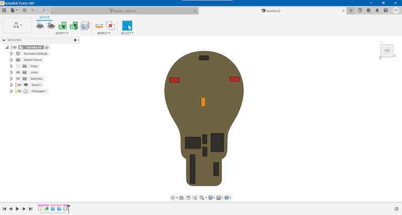
When you’re satisfied with your 3D model, save it, and then you can pull the modifications in Eagle.
In my case, I had one more step to do. I needed to import the design of my traces. Since I already draw them in Fusion I manage to reuse them but there are certainly shortcuts. The import in Eagle needed to be in a BMP format which cannot be exported by Fusion. So I first exported a PNG file and converted it to BMP thanks to a third software. In Windows, Paint can do the job.
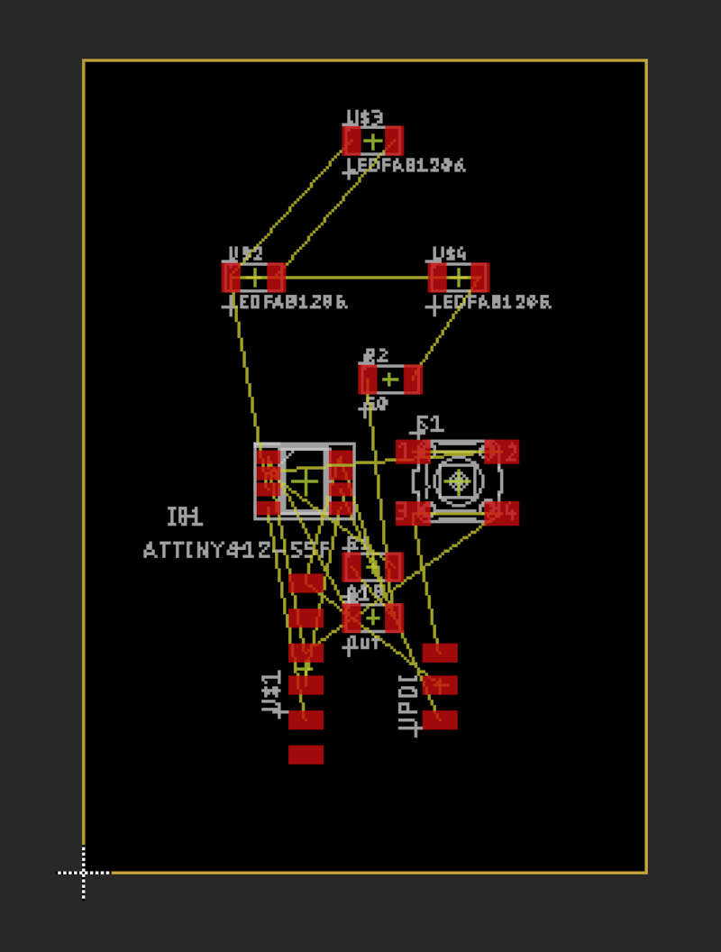
When you import your file you have to select in which layer it will appear. In our case, you have to choose the top copper layer. You also need to properly scale your picture. After it’s done, you need to move and place everything correctly one more time and normally you should obtain something like this.
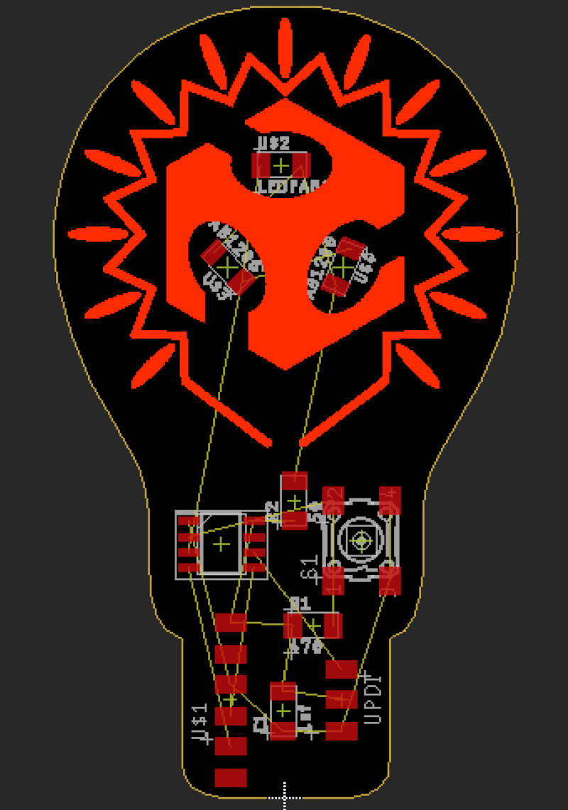
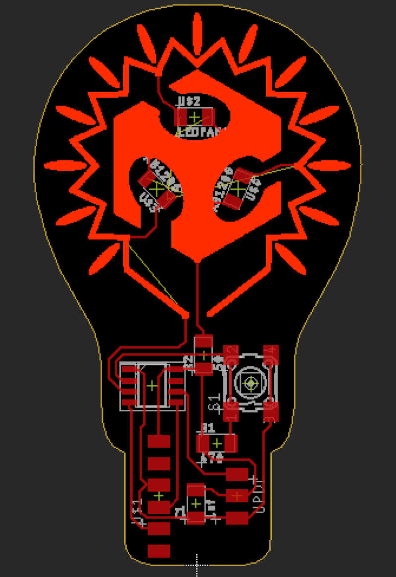
Now we only have to route the traces and the board will be finished. If necessary, you can move some components to make the routing easier. For example, look at the R2 resistor that connects the LED, it’s really helpful used as a bridge.
Milling
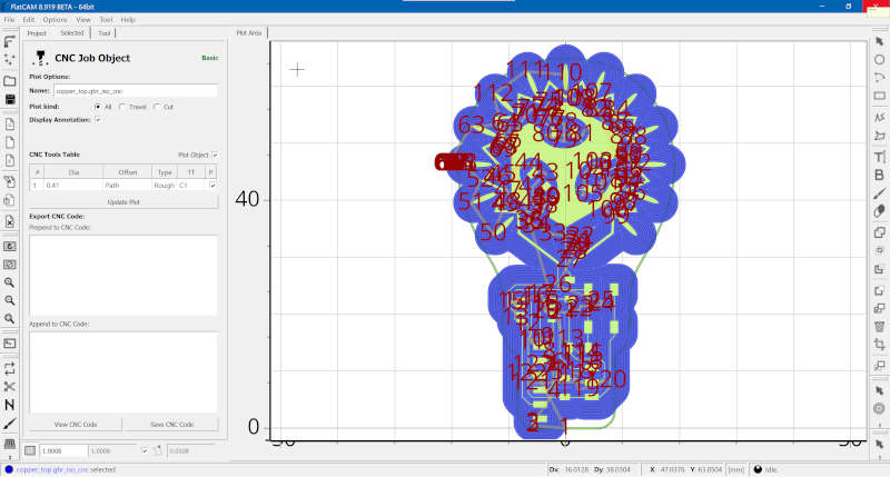
To manufacture this board, I could use Mods like two weeks ago but I decided to change and try Flatcam. For this software, it’s better to use Gerber format rather than PNG used in Mods.
Then I generated a gcode for a V-shaped mill with a diameter tip of 0.4mm, and asked it to make 10 passes.
To control the CNC, I used Grblcontrol, no need to change.
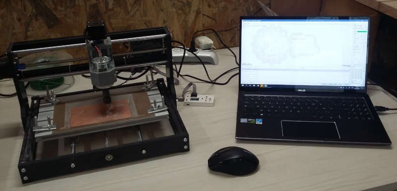
Since it takes some time, around one hour, don’t forget to check sometimes if everything goes correctly .
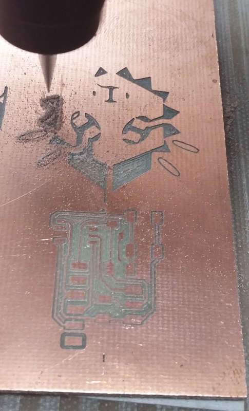
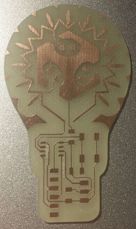
After manually clean it up this is the result :
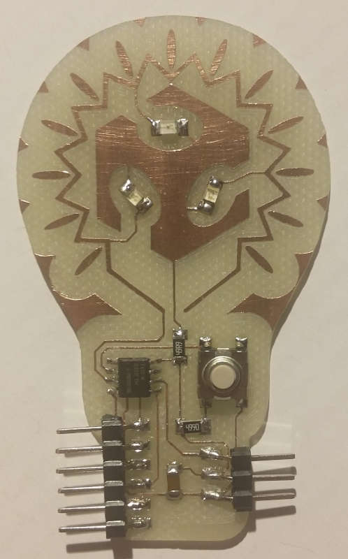
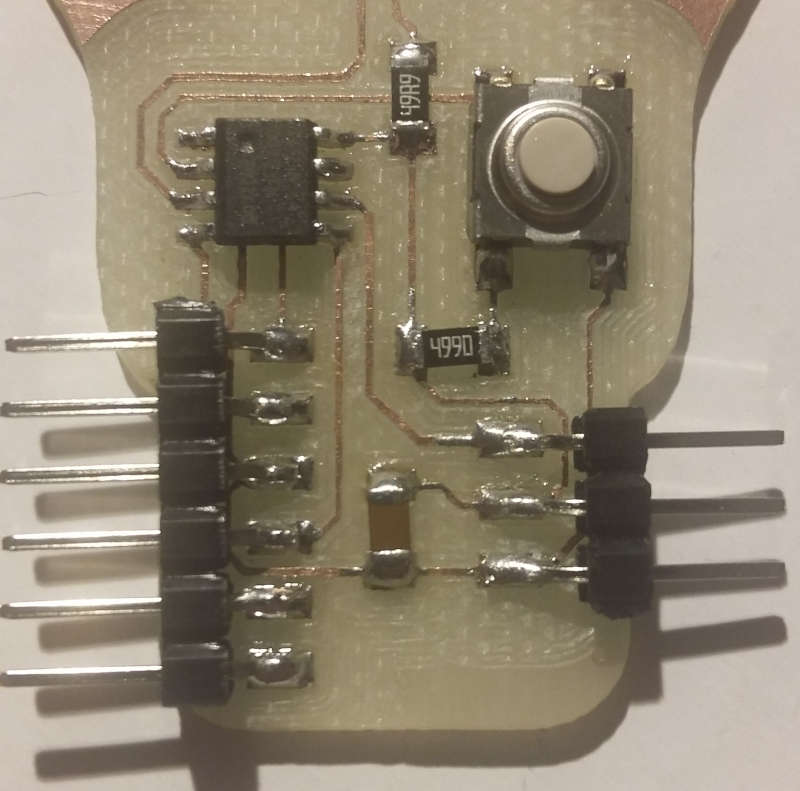
Soldering
Last but important if you want your board to do something, you need to solder your components.
Files
If you want to do the same, here are the files :
-
Eagle :
-
PNG :
-
Gerber :