5. Electronics production
This week, we learned how to manufacture a PCB with a CNC milling machine.
The CNC and accessories
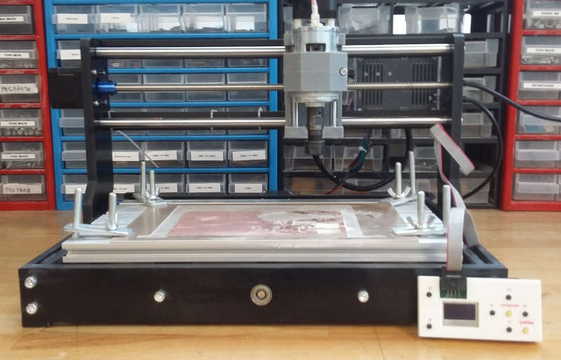
Our lab has a little 3018 SaintSmart, which was assembled by my colleague Jules Topart.
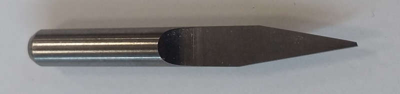
For the tools, we have two kind of mill at our disposal : - The V shape mill which has an angle of 20°. These are cheap mills but they are great to begin with to get it into our heads without risking breaking the dedicated and more expansive mill.
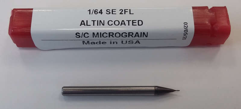
- Then we have a 1/64 mill which is perfect for PCB.
Flatness
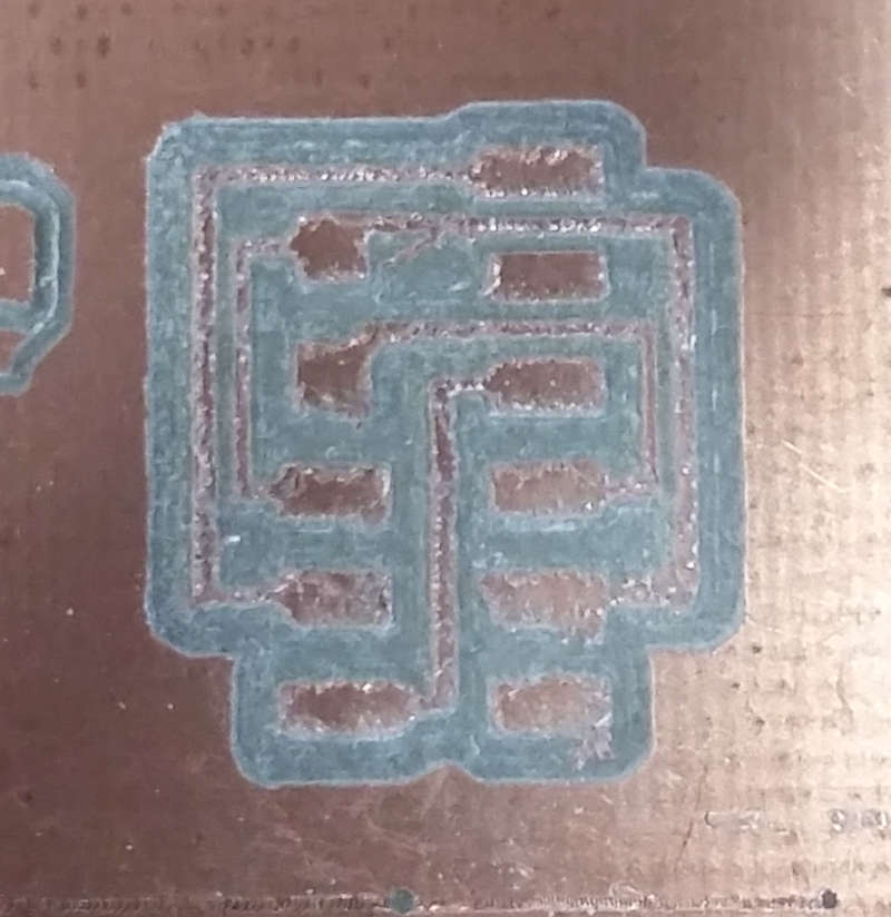
I already knew this was an issue but I wanted to demonstrate it. These machines aren’t perfect, X and Y axes aren’t necessarily aligned with the bed. However when we are manufacturing a PCB we need a perfect parallelism between the bed and the movements. If it isn’t the case traces can disappear or join themselves.
So like I said I made a first try with the machine as it is.
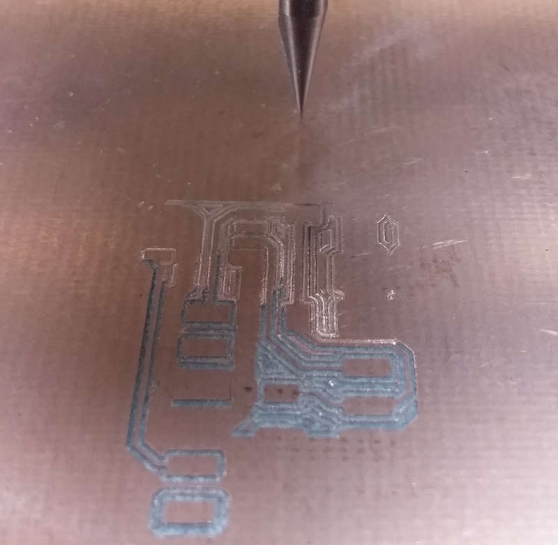
Of course, I wasn’t lucky and had the same problem as anyone else. So as you can see at the top of the picture, the traces are merging together as the bed is going down.
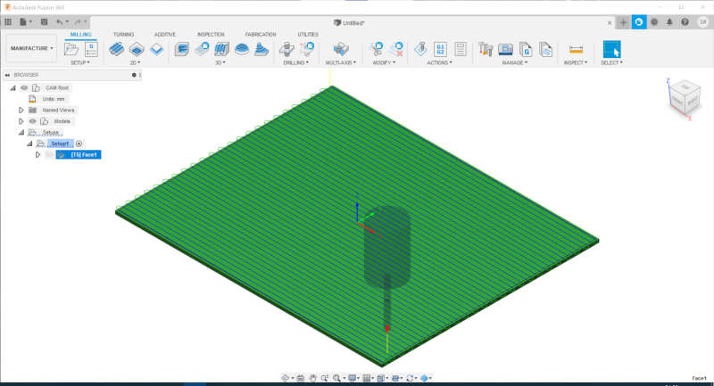
The solution to this is quite simple, we have to use a martyr and do a surfacing before placing our PCB.
To do this part, I chose a 3mm flat end mill and I used the CAM workspace of Fusion360 to make the path.
Then time to launch the machine (with Grblcontrol) but surprise a new problem but this time it was a real one.
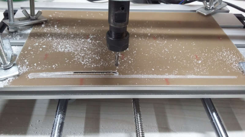
So what happened ? Even if my martyr was clamped to the bed it is thin enough to be able to bend. Then as the mill is doing its work, the helicoidal flute is forcing my plate upwards to the point where the mill is literally going through it.
Since the first line was correct I assumed everything was okay, I started to think about what I’ll do next, and wasn’t ready to stop the program immediately. This was an excellent reminder that we need to be really careful with these kinds of machines.
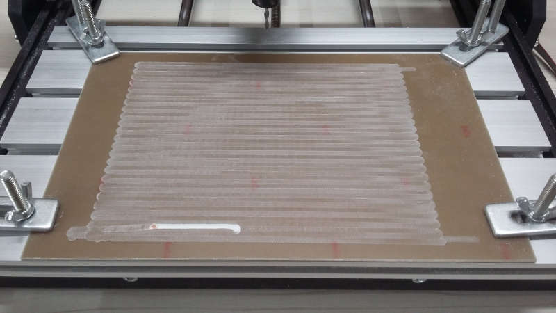
Nevertheless, the solution is quite simple, you just need to put double-sided tape under your martyr.
Line Test
Now let’s do the real task. The first thing to do is test your machine to know what it’s able to make. The test is a series of lines of different widths.

To generate the g-code, I used mods which is shared by MIT.
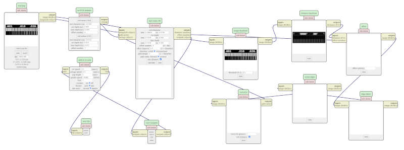
To control the machine I used Grblcontrol (Candle). The tool is a V-shape mill which has a diameter of 0.4mm.
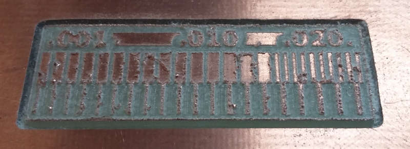
I am surprised by the result, I didn’t expect the V-shape mill to be able to make the thinnest trace but it did. For the opposite side the result was expected since it’s logical that the mill cannot etch a line smaller than its diameter.
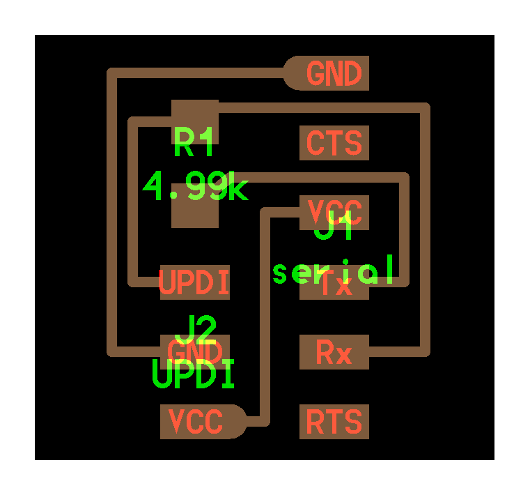
Serial-UPDI
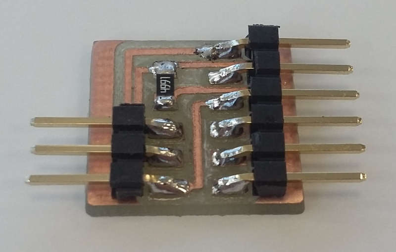
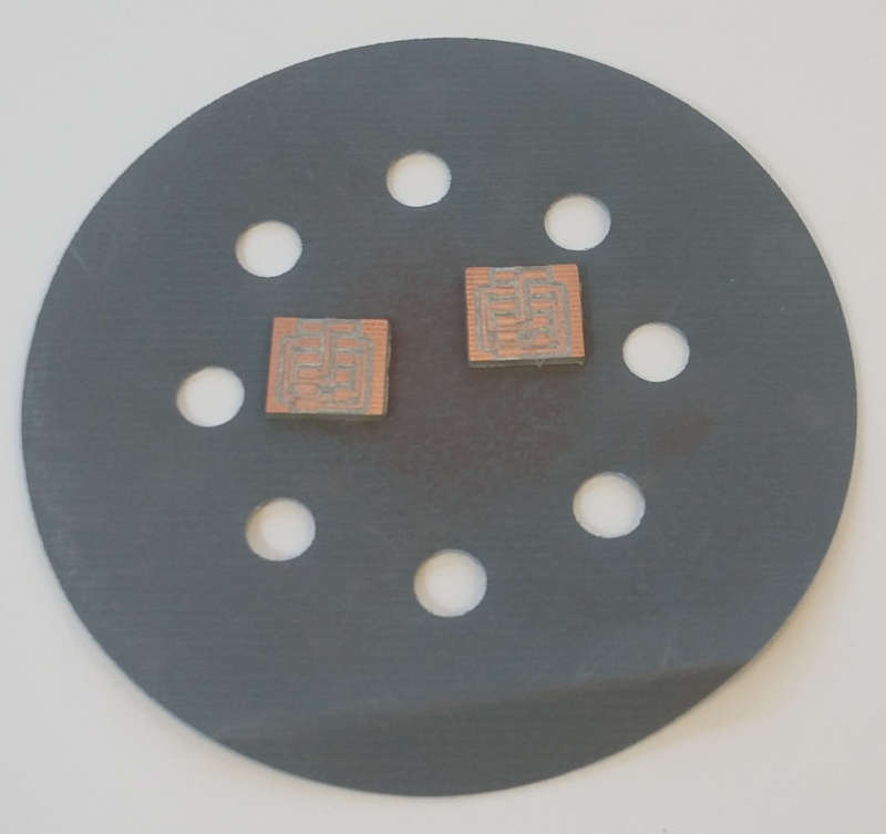
To finish we will do a real PCB and solder it. I chose to make a serial UPDI with a third pin for VCC that will be useful to communicate with the board we will create in a few weeks.
Again, I used mods to generate the g-code and still using a V-shape mill since I’m satisfied with the results and want to preserve the 1/64 mill.

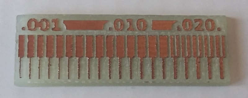
At first, the traces are really rough because the V mill doesn’t have a clean cut.
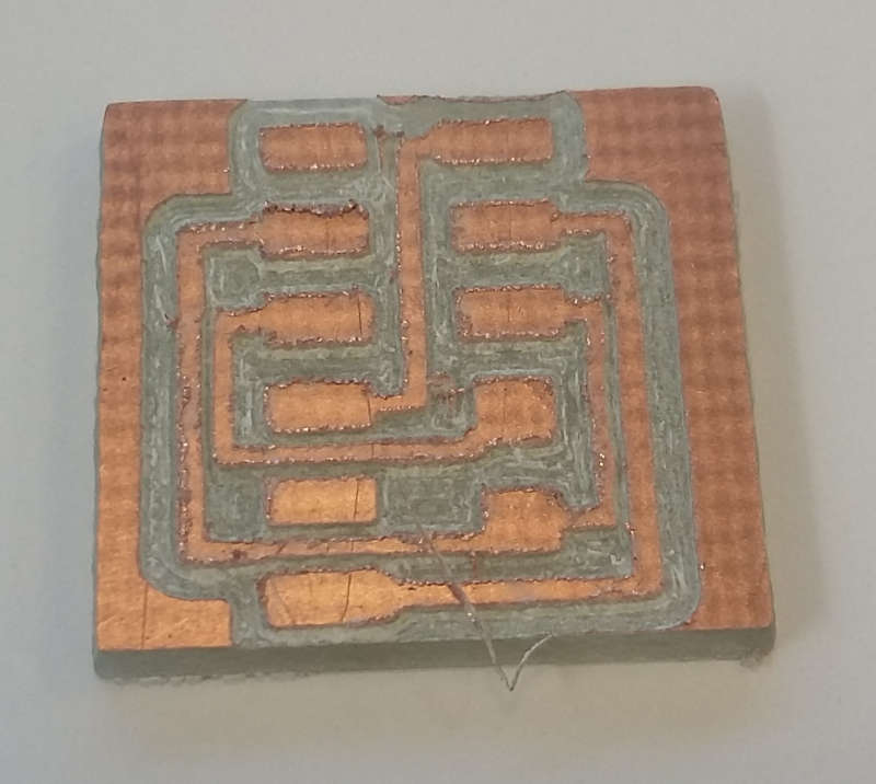
But then we sand it down.
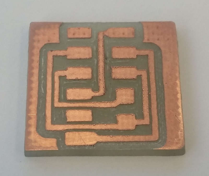
After that we only have to solder the components.