6. 3D Scanning and printing
This week was dedicated to 3D printing and scanning.
Testing the 3D printer
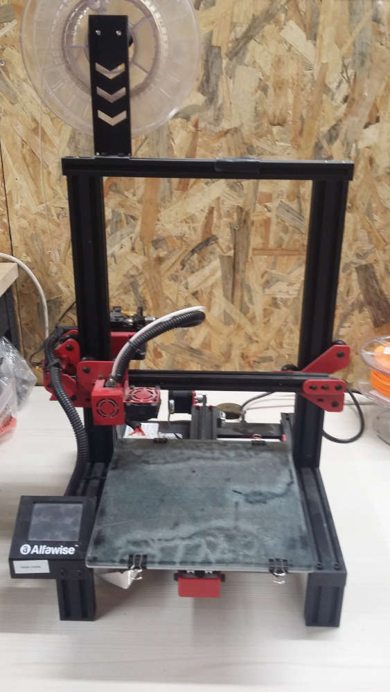
Our Fablab has a collection of Alfawise. We printed the tests on an Alfawise U30, its main characteristics are a build volume of 220x220x250mm, a 0.4mm nozzle and a heated bed.
But a printer cannot run alone, it needs to be paired with a slicer to create the g-code that will make it move. The lab mainly uses Cura which is one of the most popular slicers, however I am pretty used to Mattercontrol. So we worked with both of them.
For the plastic, we only have PLA so PLA it was. It was Esun’s PLA+, which need to be print around 210°C and if possible but not necessary on a bed heated at 60°C.
For the rest of the parameters, we used the defaults profiles from the slicers because we wanted to see what needed to be improved. But it was rather disappointing because they are already great and we don’t have to change anything important.
The main values, the ones that a beginner will see, for this standard printing profile are a layer height of 0.15mm, 2 perimeters, 10% infill and an average printing speed of 40mm/s.
Our first test was the angles test, to see how much a print can be inclined.
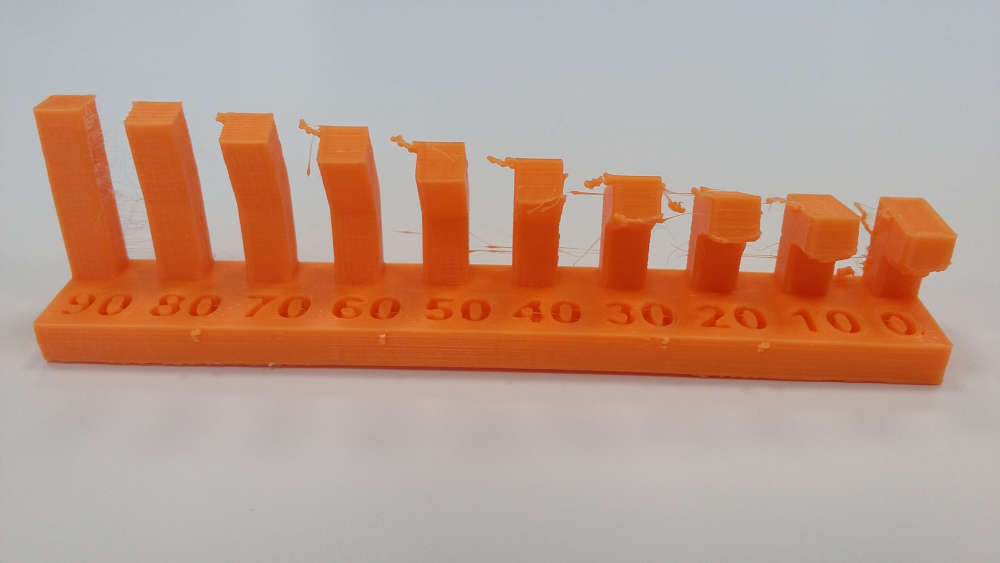
From 90° to 30° the angles are correctly printed but under these values we begin to see some visual imperfections. We can also note that the printer produces string between pillars, we can improve this default by increasing the retraction. But for now, we won’t change it since our goal was to test the profile given for beginners.
Then we wanted to print the bridges test. But you have to be wary if you are using Cura, because the bridge’s setting is not automatically enabled. To enable it you have to go in the “Experimental” section and check “Enable Bridge Settings”.
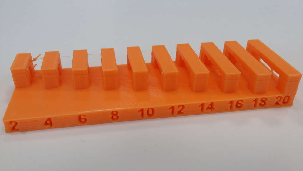
For this one, the imperfection begins when the bridges are longer than 14mm.
The following test was thickness. This time most of the job is done by the slicer which automatically removes anything smaller than the nozzle diameter. So you don’t have any risks.
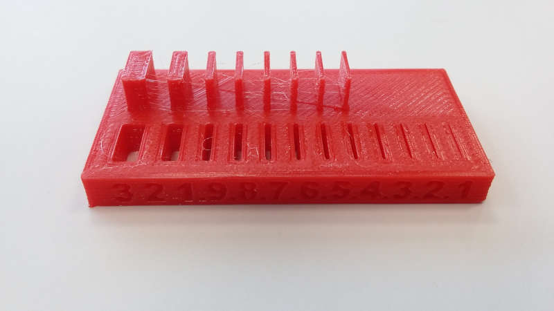
Here every is correctly printed, even the smallest slot.
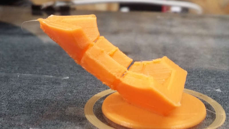
The next one, about clearances, is a little more tricky because it needs support. But we have to be careful not to have them everywhere, especially not between the axis and the moving parts. So to achieve that I used mattercontrol where it’s really easy to control and choose where you want support.
![]()
![]()
So the test in itself was great but something else happened, the layers progressively slid to the left, and this is a problem we really need to check. But we can still see the results, the parts not moving are the ones with less than 0.3mm clearances.
After that we also tried an all-in-one test.
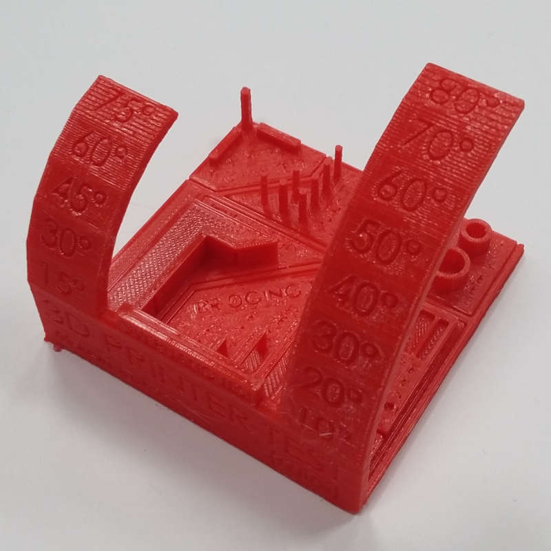
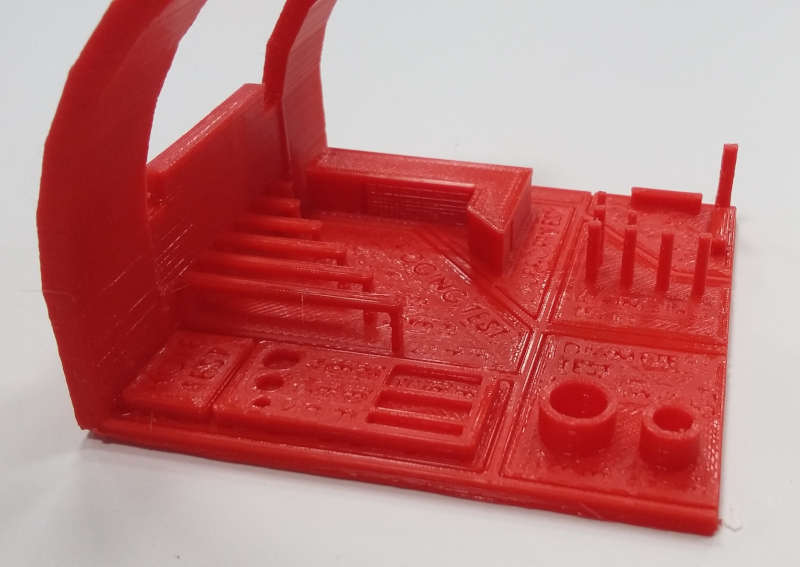
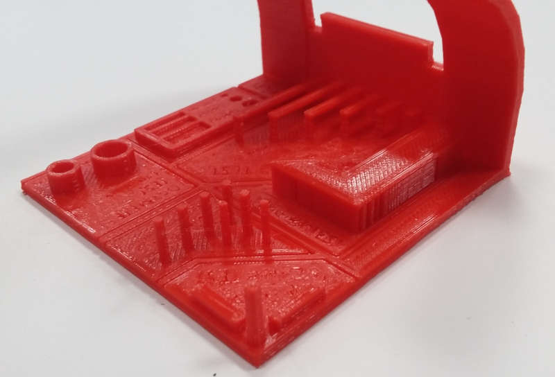
There is only one noticeable problem. The horizontal text wasn’t printed correctly and is illegible. Everything else is great.
And just for fun we made a last test, the more than famous benchy.
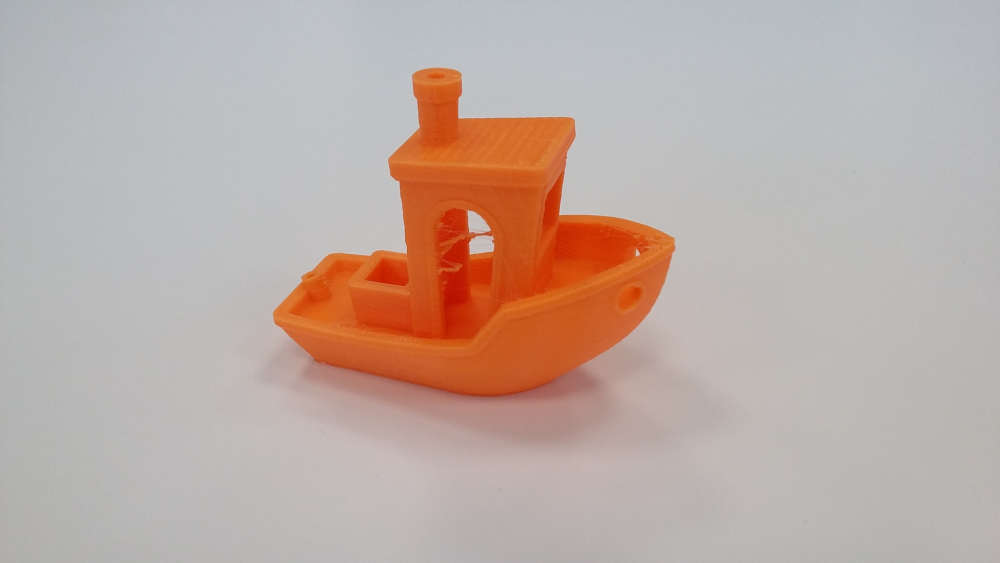
Again only one default the strings between the two sides of the door.
Personal design
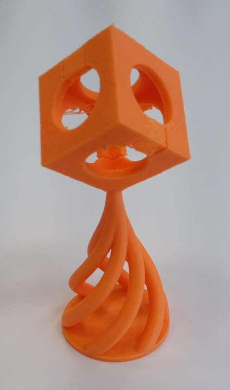
My idea was to make some kind of trophy using the fablab symbol. So I transform the 2D picture into a cube and I simply put it on a twisted pedestal.
I purposely add a helical shape that makes it impossible to manufacture subtractively or by molding.
To avoid support, I was careful not to create angles under 30 degrees for the trophy’s foot. But for the cube I had to use an already existing shape and of course it needed support. However, this cube is at the top of the trophy and I don’t want to have support going all the way from the bed. It’s always better if we can avoid wasting material.
In Cura slicer, we can define specific objects into support but we still have the same problem. The slicer is working vertically and if the chosen objects have nothing under them, the support will start from the bed.
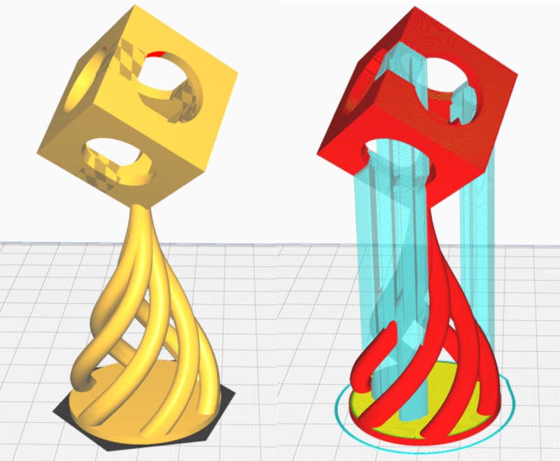
I tried several other slicers but most of them work in the same way. I found what I was looking for thanks to Mattercontrol slicer. The difference is that you can convert specific volumes into supports without them starting from the bed. This is offering us many possibilities, we can create local support anywhere and the support can have any shape.
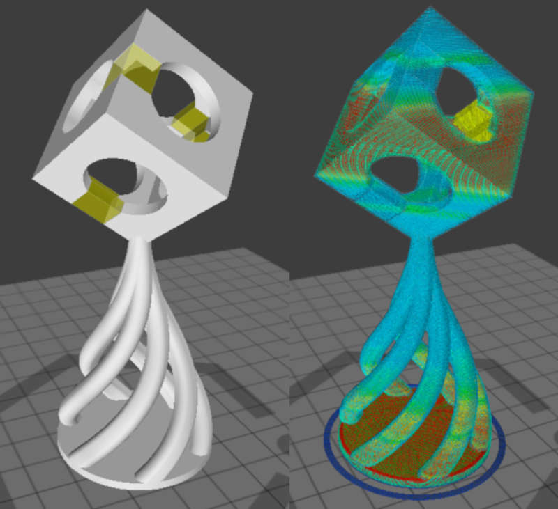
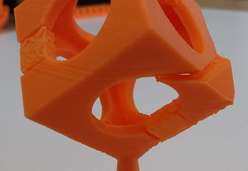
A little closer to see what’s really happening.
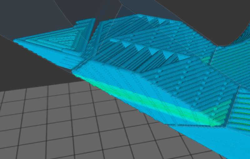
As you can see my supports are bound in the shape I created. They are like a part of my piece, but I have full control over the air gap.
Of course, I never launch a print of several hours with some doubts at the top. So I try beforehand to print the small part containing what can cause a problem.
The gap between the part and the support is 0.5mm, the assembly is strong enough to stay still when printing but remains easily breakable by hand.
Being satisfied, I launched the whole trophy. However when we play with fire we also burn ourselves. Only 2 of the 3 supports worked. Nevertheless, the third one didn’t break completely, he just bent a little bit and the printer was able to finish.

So next time I will decrease the air gap of the support from 0.5mm to 0.2mm. I want the supports to be stronger even if I can’t remove them by hand, a cutter will do the trick.
Scanning
Our lab has an Xbox kinect so we played around scanning each other.
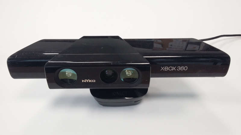
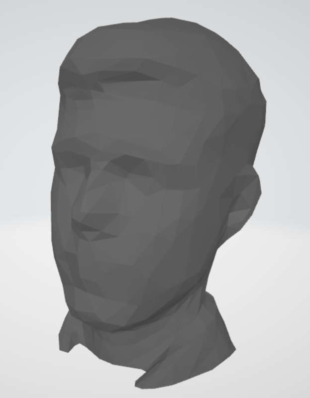
The software to control this scanner is called Skanect, below is a screenshot of this software in action (scanning me).
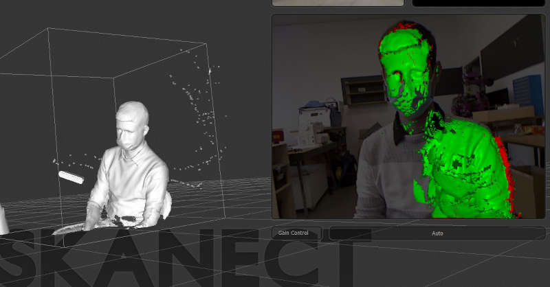
At the beginning we missed some areas, like behind the ears, the top of the head and under the chin. But with a few more tries we could obtain some great results.
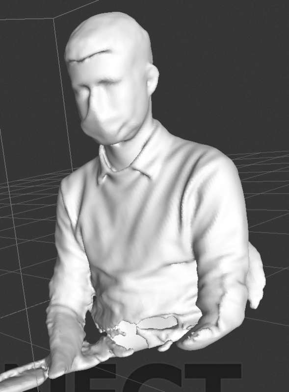
What was disappointing was to have a free license which limits the number of facets when exporting. The result is pretty artistic.