4. Computer controlled cutting
This week’s topic was computer-controlled cutting.
The Laser
The Laser I’m working with has a power of 60W. It has a control panel on the top for file management and horizontal movement. On the side , we can find the height adjustment for the worktable and switches for the laser as well as the power supply.
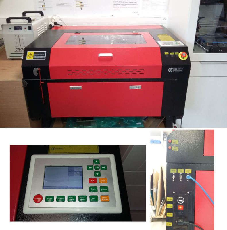
Moreover, to run it properly, we need a cooling circuit going directly through the Laser, an air extraction to evacuate fumes and a pump that sends air to the cutting area to avoid fire.
Laser’s adjustments
The first thing to do before cutting anything is to adjust your machine according to its characteristics and those of the chosen material.
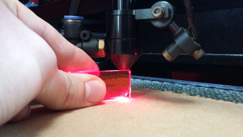
Calibrating the focal length is easily done using the gauge supplied by the laser manufacturer.
On the other hand, the other settings are obtained after a series of tests. Each material requires a different power-to-speed ratio, to find the best values, I cut comparison charts showing which parameters work and which not.
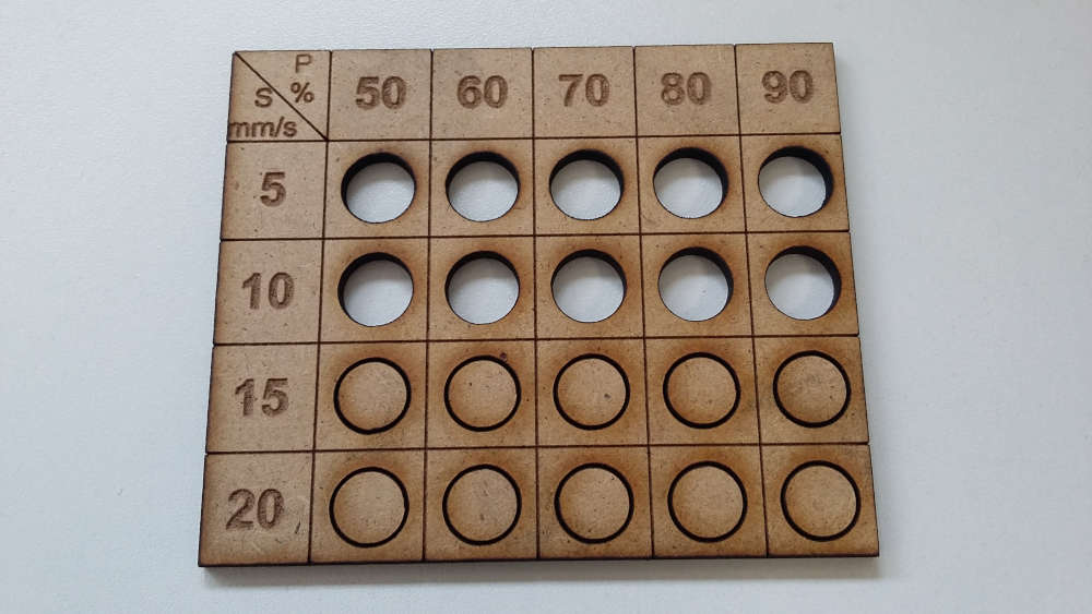
We often notice that the parameter with the most influence is speed. We can obviously refine these values by doing more precise charts. But I am wary of the parameters just at the limit because the material is not necessarily uniform and can be easily cut in some areas and still in one piece not far away. Only experience can help in this case.
For this material, I’m using a power of 80% (of 60W) at a speed of 10 mm/s. It works most of the time but I still have some surprises from time to time.
The following test is specific to the laser. To make assemblies between different laser cut parts, we need to know the diameter of the cutting beam (kerf) to adapt the dimensions and clearances directly in the design on the computer.
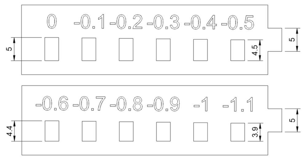
To find the most suitable dimensions, I created a two-part test with a 5mm lug and a series of notches that gradually decrease in length by 0.1mm.
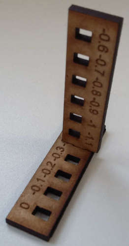
Once cut the lugs only measured 4.8mm instead of 5mm and the notches were 0.2mm longer. The perfect fit is also with the smaller 0.4mm notch. We can therefore deduce that the kerf is 0.4mm.
Files of the tests :
Table kit
In a few weeks, we’re going to have to make something big. Already having an idea, it was an opportunity to make a prototype and see what it would look like. This is a terrarium table for indoor picnics.
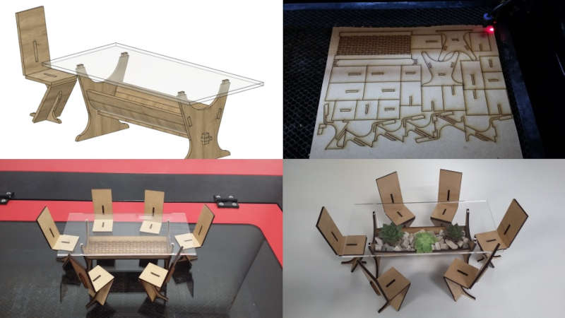
Here are the files of this prototype :
Construction kit
This week’s assignment is to design a universal construction kit. Since the geometric shapes all have different angles but I would like to avoid having too many different parts, I decided to create a flexible connector with endless possibilities.
But first let’s begin with traditional assembly parts. What I mean is that I created parts that can be put together directly with fixed angles. I made several connectors from triangle to hexagon.
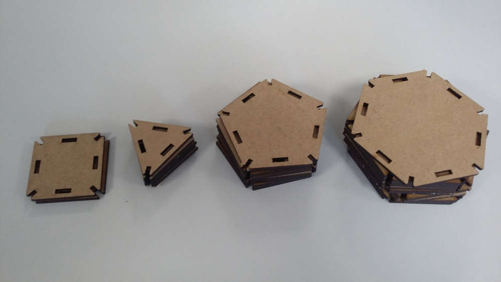
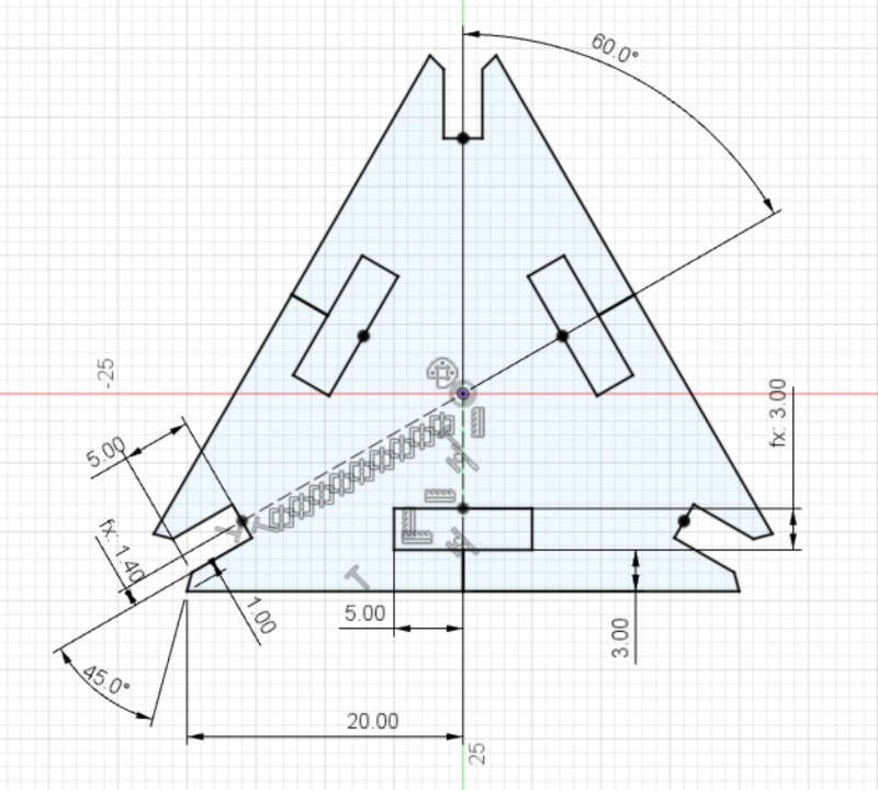
These parts are designed in Fusion360 with parameters like the thickness of the material and the kerf of the Laser. I simplified the sketch by drawing only one half of an angle which was then mirrored and duplicated with a circular pattern.
You can see below an example of the kind of structure we can get by connecting them.
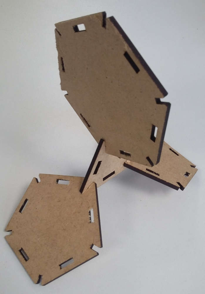
So even if I stopped there, our imagination could already run pretty wild. But I wanted to make something different and special.
As I said earlier, I created a flexible connector to cross the barrier of fixed angles. However, this was a tricky part to achieve. I tried several patterns and dimensions to obtain a connector with enough flexibility but also not too brittle.
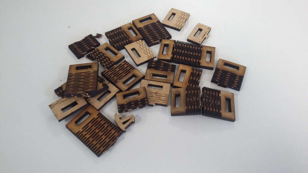
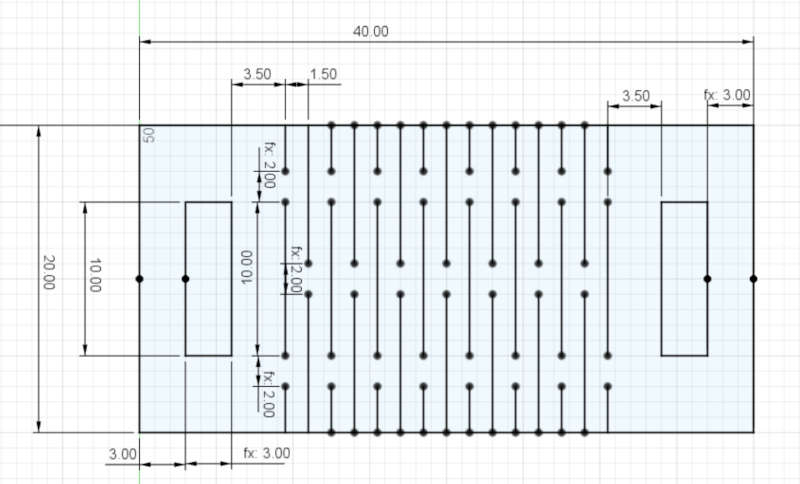
This design is of course parametric like the rest, but you will probably need to redraw the pattern each time you change the material since it depends on its physical properties.
Nevertheless, I’m sharing the features of my design that I think are the best in my case. I made 10 mm long lines spaced 2mm longitudinally and 1.5mm parallely.
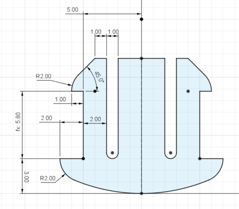
I then created a clip to hold two parts one on the other. The height is also adaptable to the thickness of the material. But the width of the slots is probably linked to properties of the material, so think about testing it beforehand.
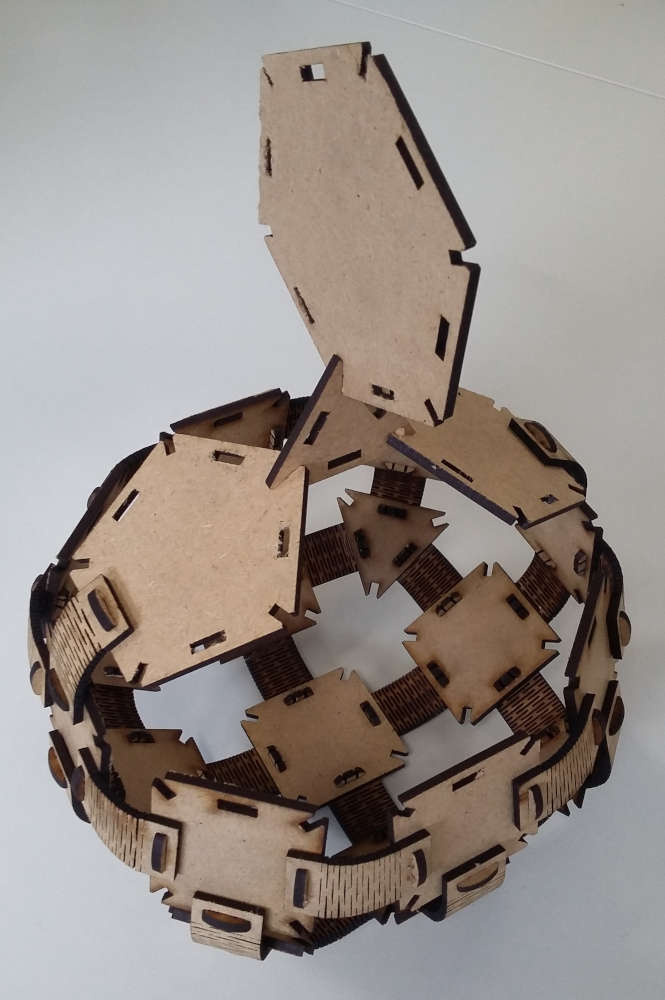
Now we just have to play with it and build anything. My idea was to make a polyhedron with different shape sides and show the versatility of my connectors.
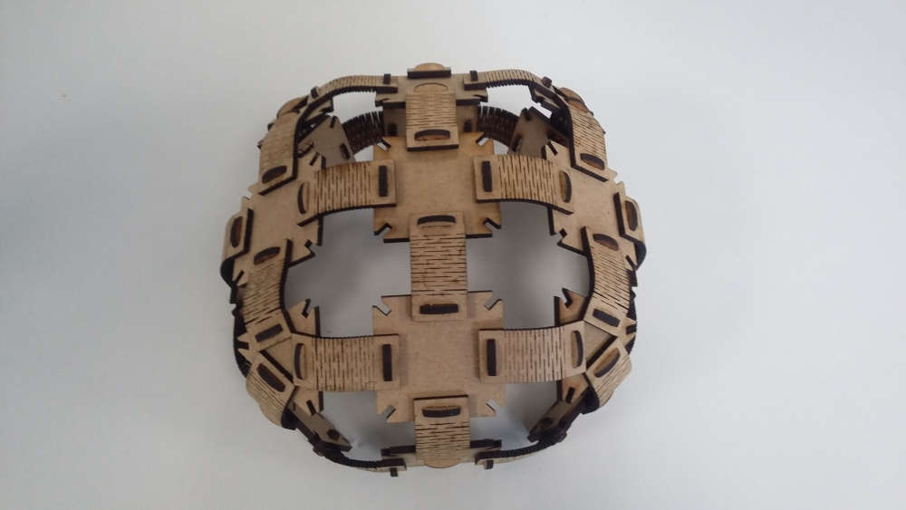
But I stopped in the middle and connected my first basic creation and this was a revelation, I obtained a little basket.
And of course, for your personal entertainment, here are the files :