Embedded Programming
week 8 assignment is to read a microcontroller data sheet and to program the board (which created on week6) to do something, with as many different programming languages and programming environments as possible
Embedded System
Multiple components interfaces jointed together and also embed in to a chip or chip based board for performing a dedicated task is called embedded system. Mostly in a Embedded system contains a programable chip like Microcontroller ,Microprocessors or FPGA chip etc..
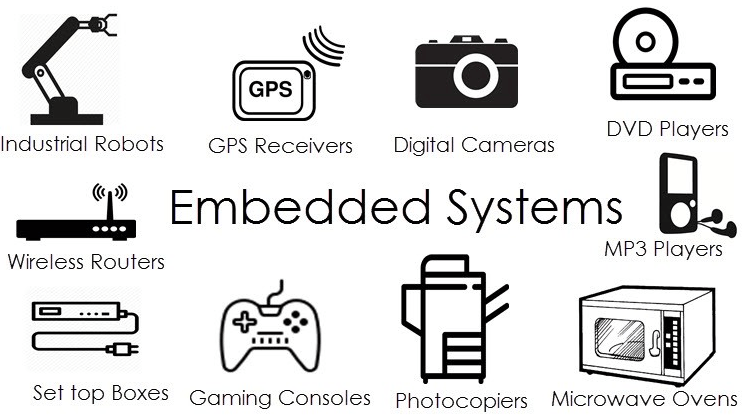
The Picture shows the applications of embedded system in Everyday life.many of them based on microcontrollers
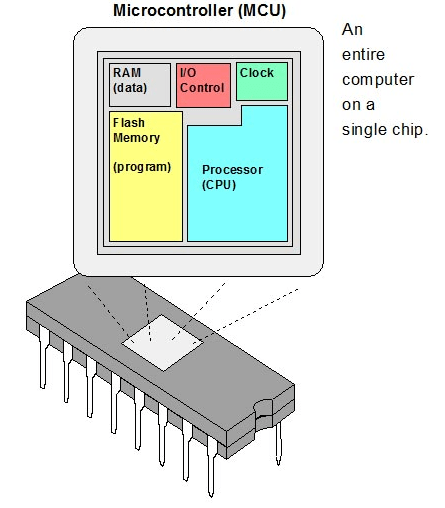
Microcontrollers
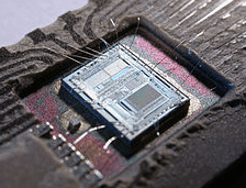
we all know about computer and its CPU Unit.Microcontroller is like a CPU unit of a Computer it has RAM,ROM,BUS,I/O Ports,Processor everything embed into a single silicon chip.
The below picture shows internal blocks of a Motorola microcontroller which is introduced in 1978.they called "computer on chip" ,source link
Atmel AVR Microcontroller
The board that I made during electronics design is based on an Atmel AVR Chip called Attiny84.Atmel was a company who make AVR series 8 bit single chip using modified Harvard architecture called RISC.Recently another chip making company called Microchip Acquired atmel.So all the supports of AVR is now coming from Microchip
During my electronics engineering diploma course I explored 8051 and AVR architectures well and made many projects and programs using 8051,Atmega328,Atmega8,Attiny85,Attiny45 ..etc.. So this is the first time I'm using Attiny 84
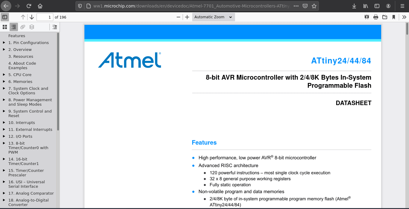
I found the Atmel Attiny24/44/84 datasheet online from microchip website. This chip created Based on Advanced RISC Architecture.24,44 and 84 are same design only the memory capacity is different 84 has more program memory than 44.
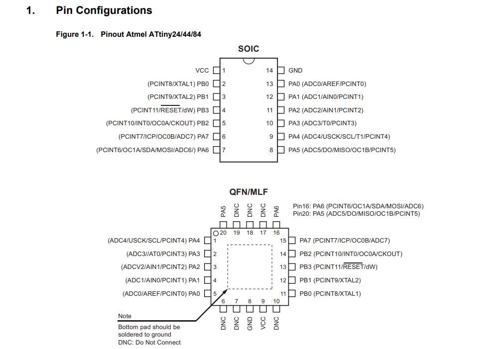
After the Specifications and features of the particular microcontroller, In the data sheet shows the its pin diagrams of different packages and its pin details. This diagram must be refereed while we design the circuit with Attiny 84. from this diagram we can understand this microcontroller available many packages like SOIC and QFN,MLF.
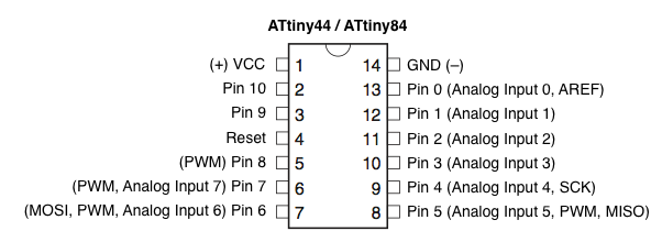
But during the designing of the echo board I was following this diagram and ofcourse this wasn't the actual also this is not wrong .This diagram was built by following the arduino support by the open hardware community to use the chip using the arduino and I did programed the chip in arduino during my Machine week
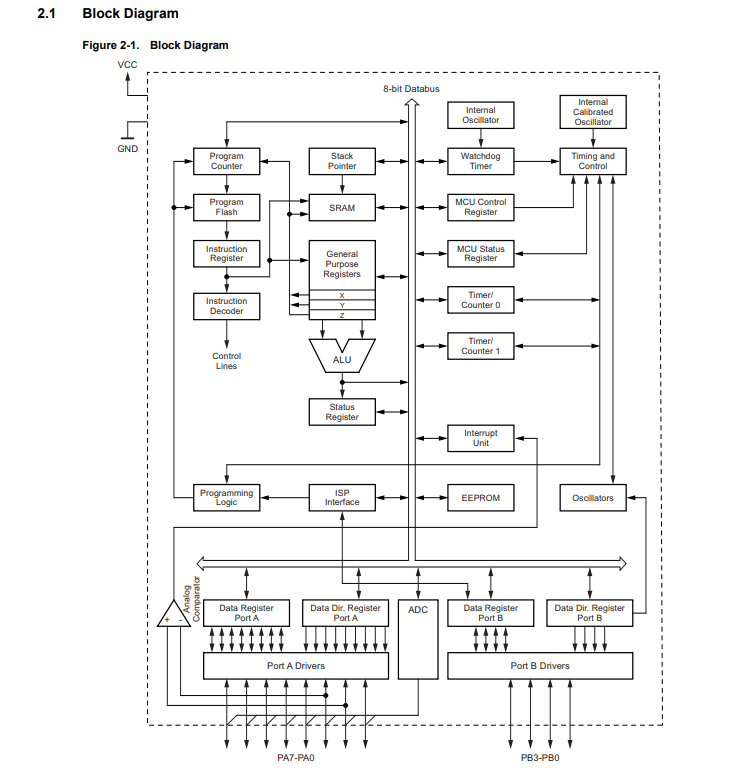
Here is the whole block diagram of the Attiny 84 which helps to understand how thing are works inside this Attiny Microcontroller
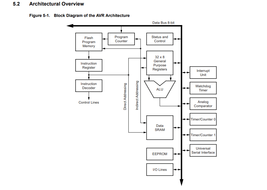
This image represent the block diagram of RISC-V architecture implemented in the Attiny84

Programing
Actually I did program the board during the Electronics design week using the arduino and the avrdude tool chains.So this week we actually learn that how its program and what are the codes for program and etc..
Our instructor Mr.Yadu guided us through the AVR tool chain and the basics of the Programing in Embedded C language.His Instructions classes help us to understand more about the tool chain and embedded programing for me it was a revision because all these basics I where learned during my diploma.
With avrdude
avrdude is a tool provided by Atmel to communicating with the Atmel MCUs for flashing,erasing,reading..etc.. . So using the avrdude toolchain and avr gcc compiler we can create programs and compile then program to the Atmel microcontrollers.
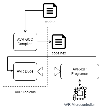
Using draw.io I drew the above diagram for giving an understandable workflow of how the AVR tool chain works. first the given 'code.c' will compile using AVR-GCC and the 'code.hex' file will be created. Then we use the avrdude for writing to the microcontroller using the AVR ISP programer.
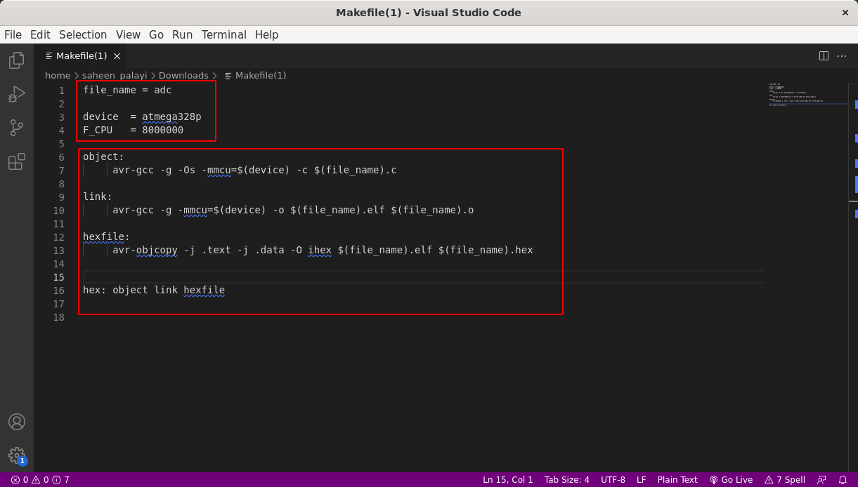
Here is the AVR-GCC compiler and '.hex' file creator makefile which I got it from Mr.Yadu and he explains the process line by line. In this file the first above things mentioned has to be change as per the code file name and MCU we uses and also the crystal selection. There is two process having in the code before creating the hex file for the code.
Yadu shared a documentation which contain a code for button and led in embedded C programing for AVR microcontrollers from electronicsome.com tutorials. It uses a button to initiate blink a LED
AVR C Button Blink CODE :-
                        #include < avr/io.h>
                        #include < util/delay.h>

                        int main(void)
                        {
                          DDRA |= (3 << PC0); //Makes Third pin of PORTA as Output
                          // OR DDRA = 0x01;
                          DDRB &= ~(2 << PD0);//Makes Third pin of PORTB as Input
                          // OR DDRB = 0x00; //Makes all pins of PORTB input
                          while(1) //infinite loop
                          {
                            if(PINB & (1 << PB2) == 1) //If switch is pressed
                            {
                              PORTA |= (1 << PA3); //Turns ON LED
                              _delay_ms(3000); //3 second delay
                              PORTA &= ~(1 << PA3); //Turns OFF LED
                            }
                          }
                        }
I took the example code from website and made changes according to my board . The modified code show in the above snippet.
Atmel Studio

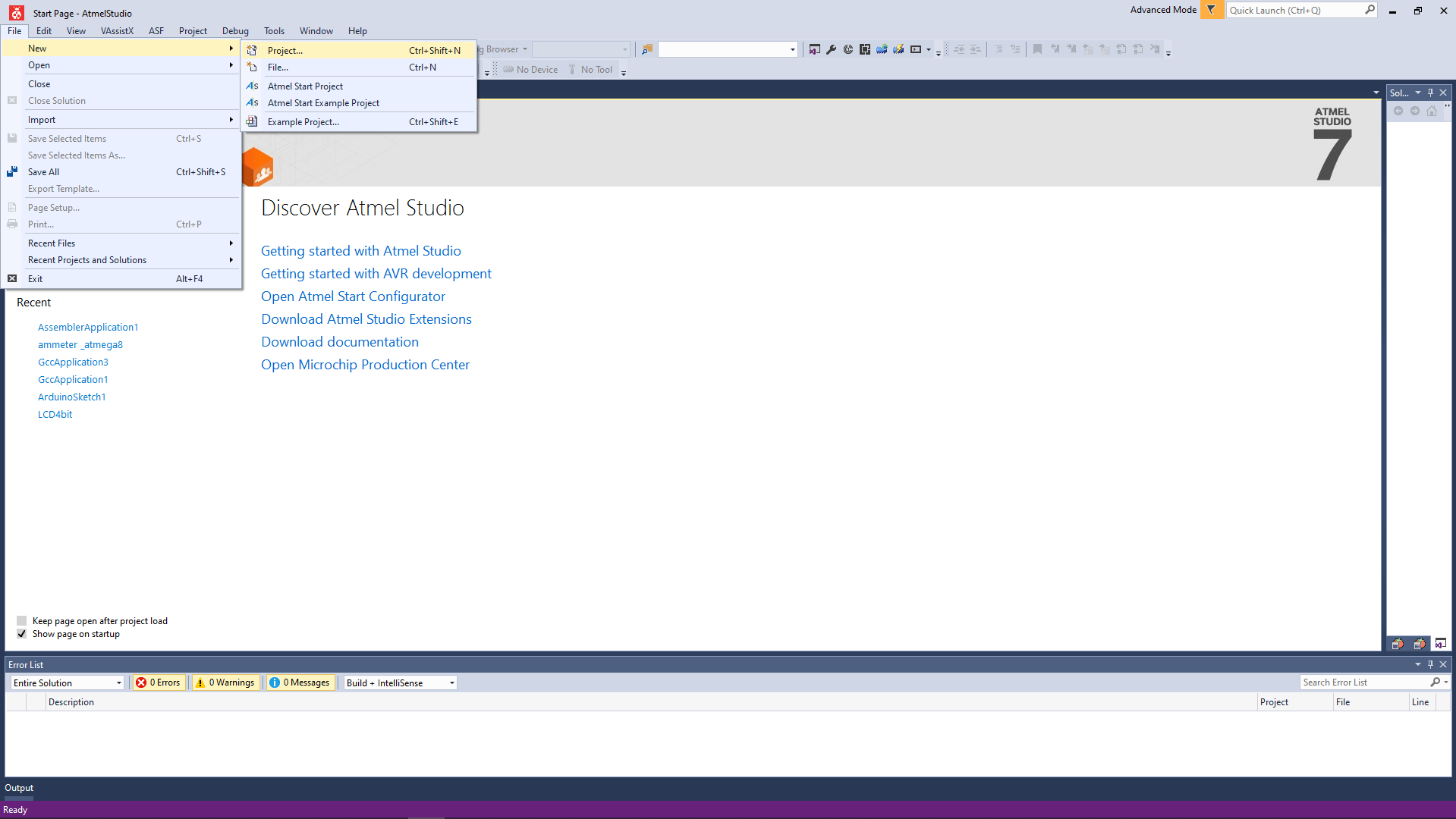
So I've opened a new project in AVR Studio by clicking File>>New>>Project
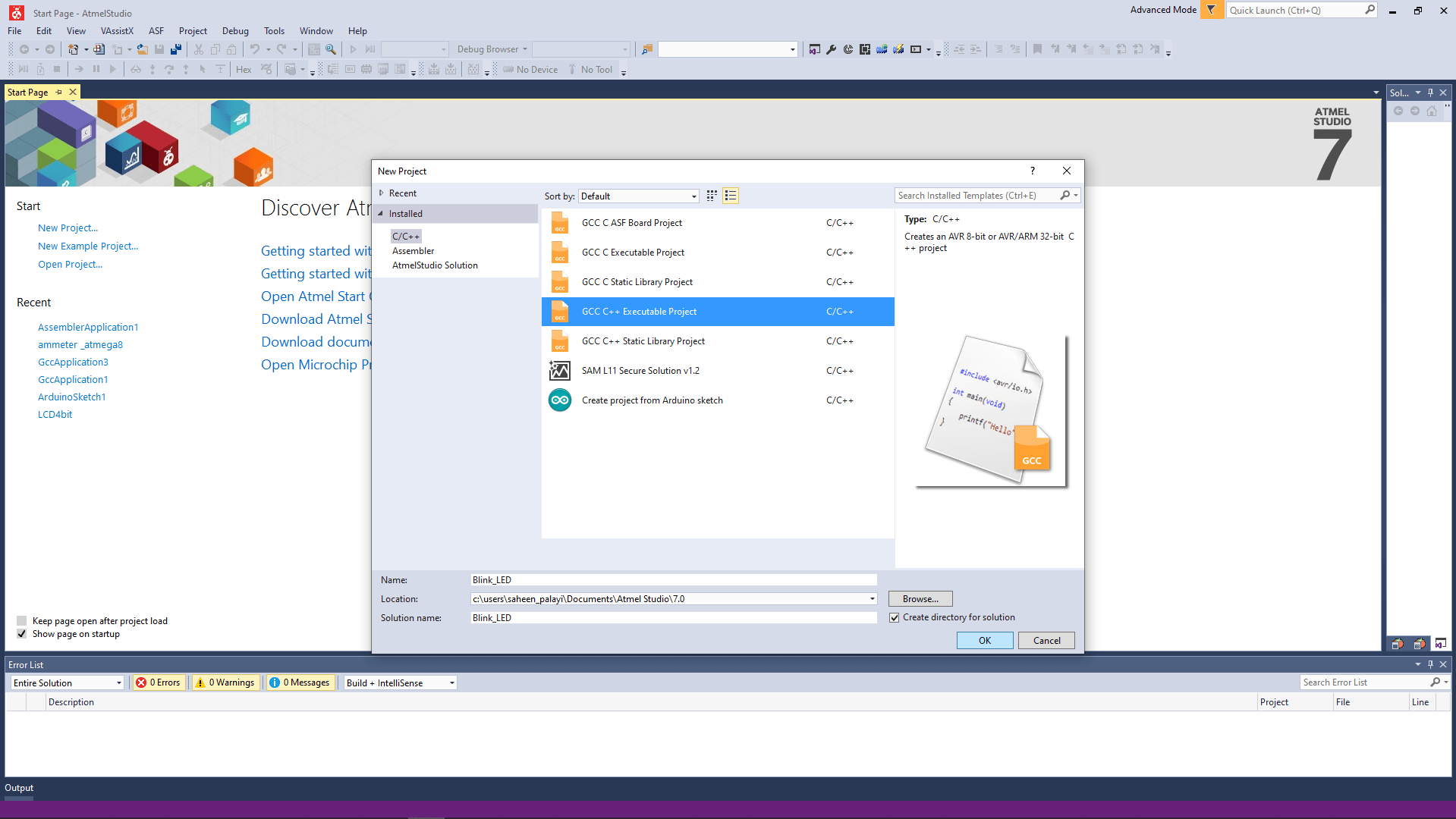
Then I selected the GCC C Executable project (The image showing the wrong one so it's gonna support both C and C++) and gave the project name as "Blink_LED" then clicked 'OK' for next.
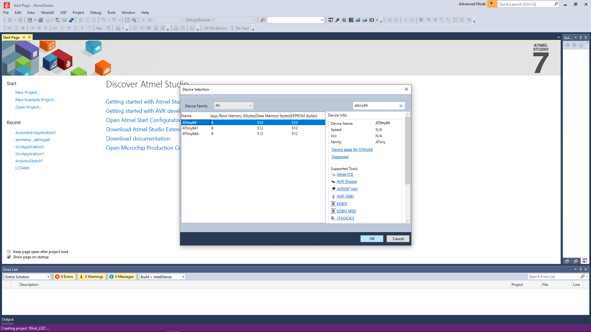
From the next window I search for Attiny84 and selected .we can also find all the files and links related to the microcontroller we are gonna use.
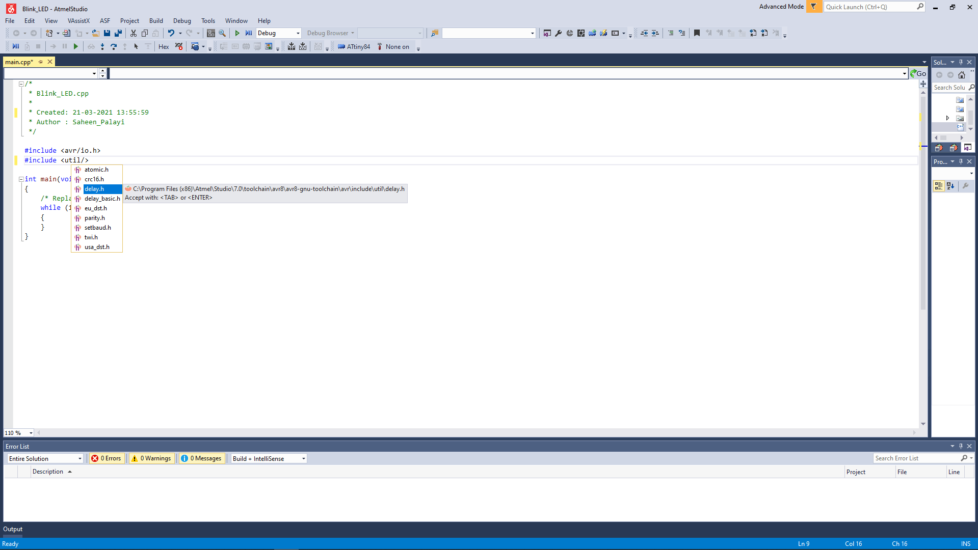
Then it opens a main.C (main.cpp in figure) file with a pre template to make our coding easy. I've start to write a blink code by adding the time delay library.You can see the keywords are showing up while I type in the document that's one of the good thing about the AVR Studio.
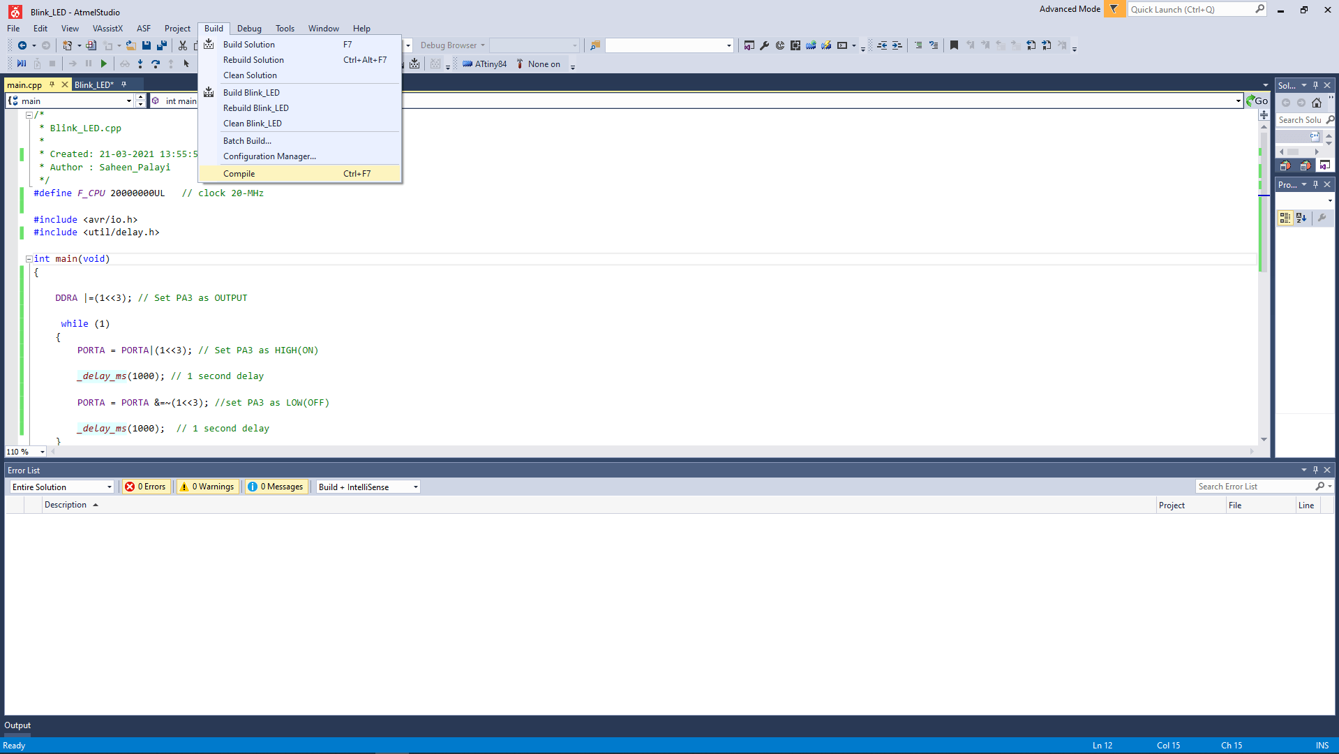
After I completed the program writing I go to build>>Compile to see errors if any . I've done this before while I'm at college so I didn't made any error
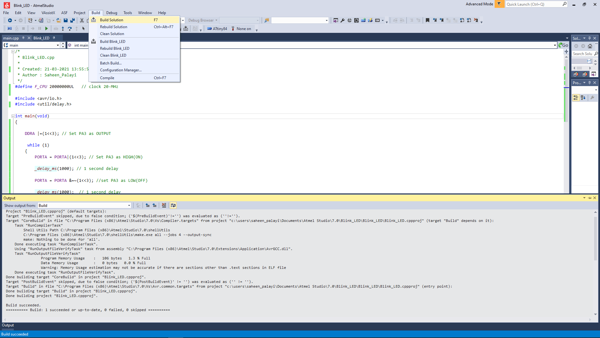
Compiling isn't enough in AVR Studio and needs to convert to hex file for program to my echo board so I clicked the build >> Build Solution for creating the Blink_LED.hex.
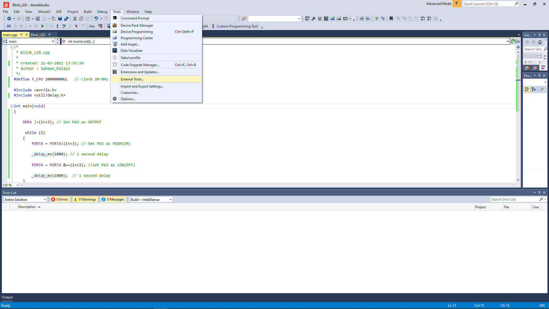
In order to program fro the AVR studio we need a official programer suggested by Microchip Atmel so I've to add an external tool for using my FAB tinyISP. I was following Salman's Embedded Week documentation so I started to added a new tool by clicking Tools>>External Tools.
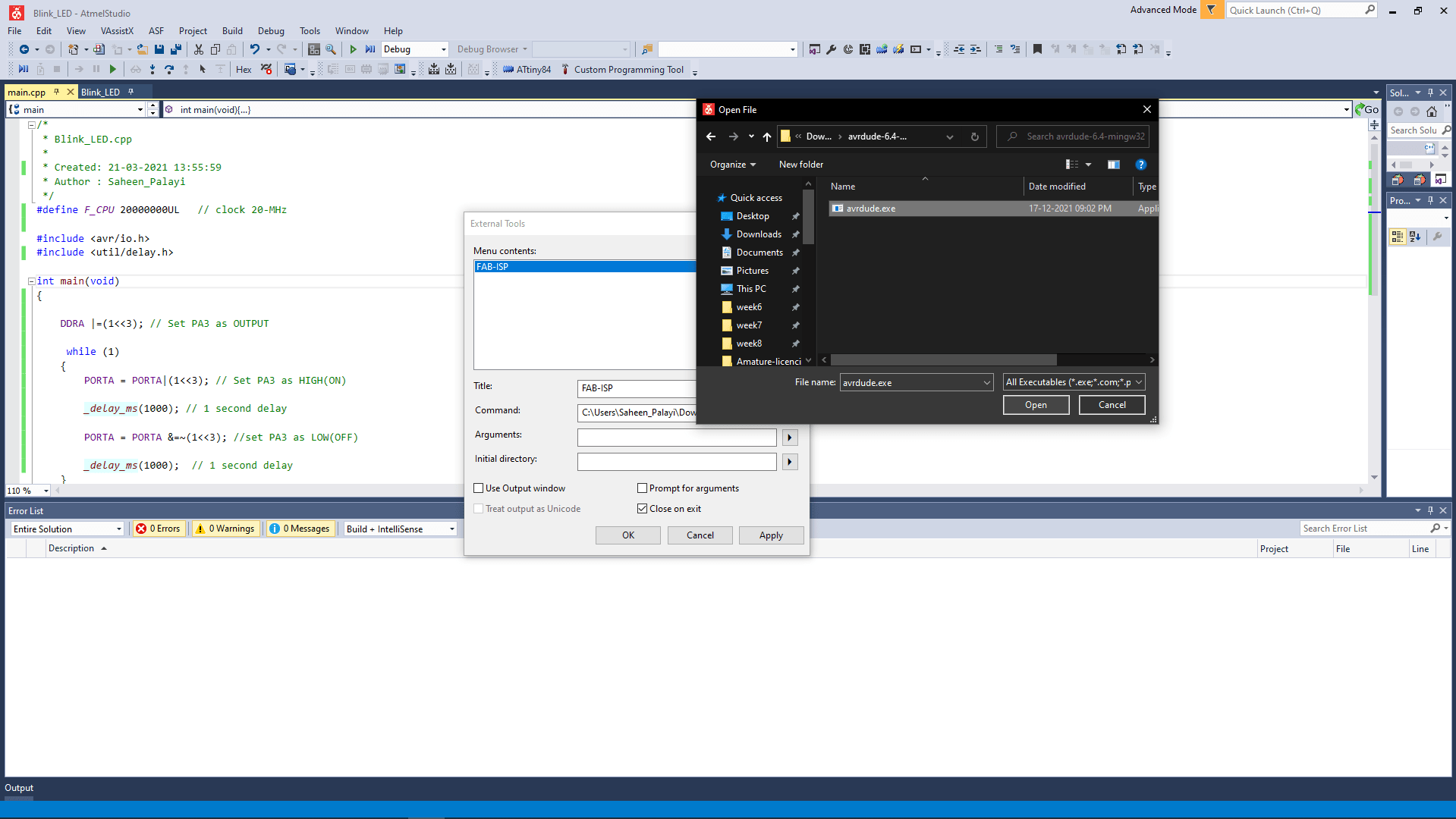
Then I added a new tool and named FAB-ISP and for the tool avrdude for windows I downloaded from nongnu.org and unzipped to folder then I selected the folder in the external tool adding process as tool 'Command'.
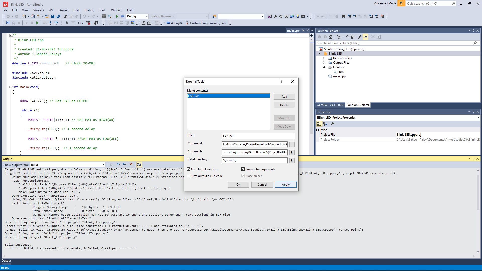
-c usbtiny -p attiny44 -U flash:w:$(ProjectDir)Debug\$(TargetName).hex:iI entered the code above as argument and then checked the boxes like in the picture and Clicked the 'Apply' to complete the adding process.the tool Appeared in Tools menu as 'FAB-ISP'.
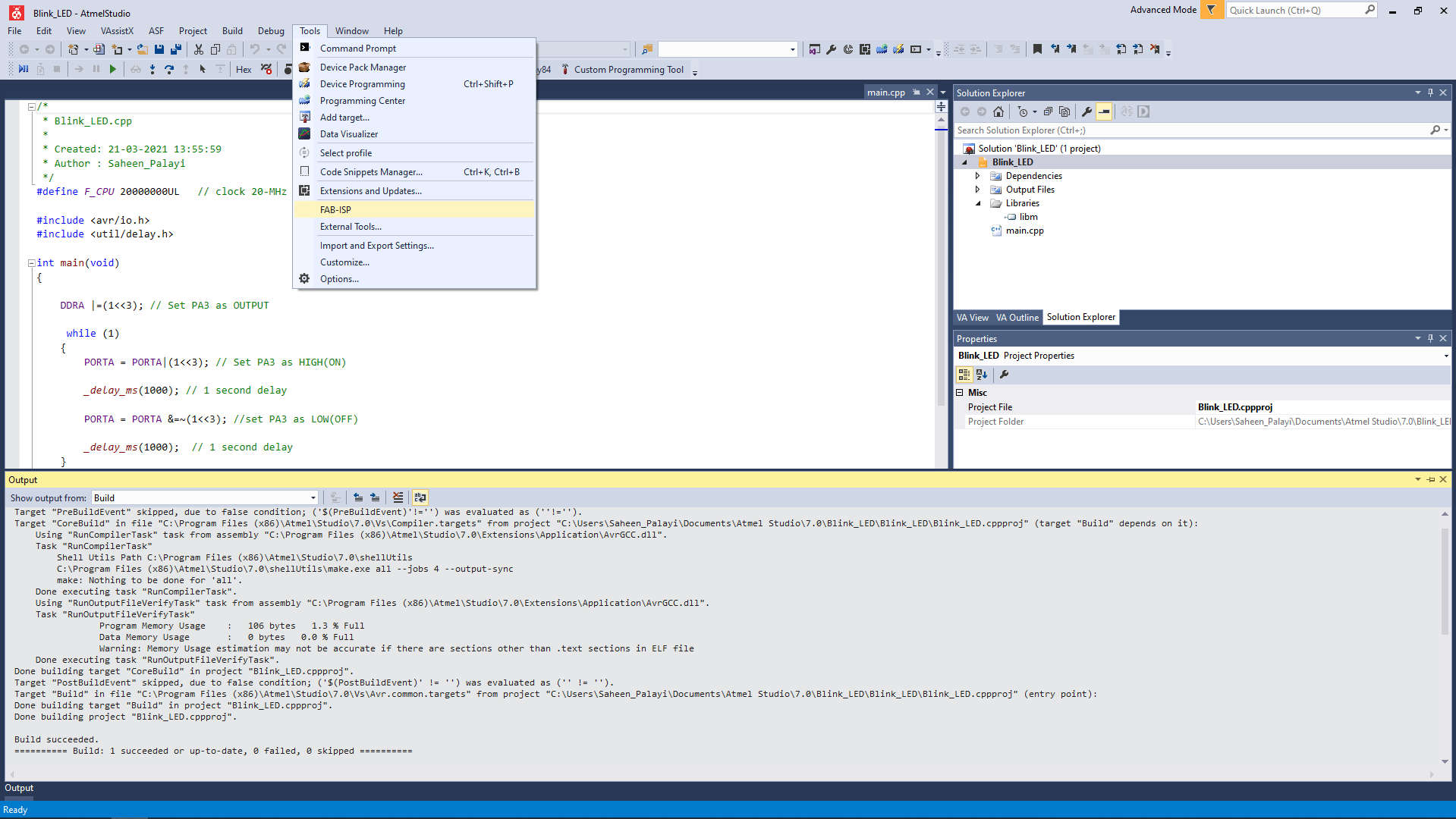
Then I connected my board to computer with Fab ISP then clicked tools>>FAB-ISP for flashing the program to the echo board.
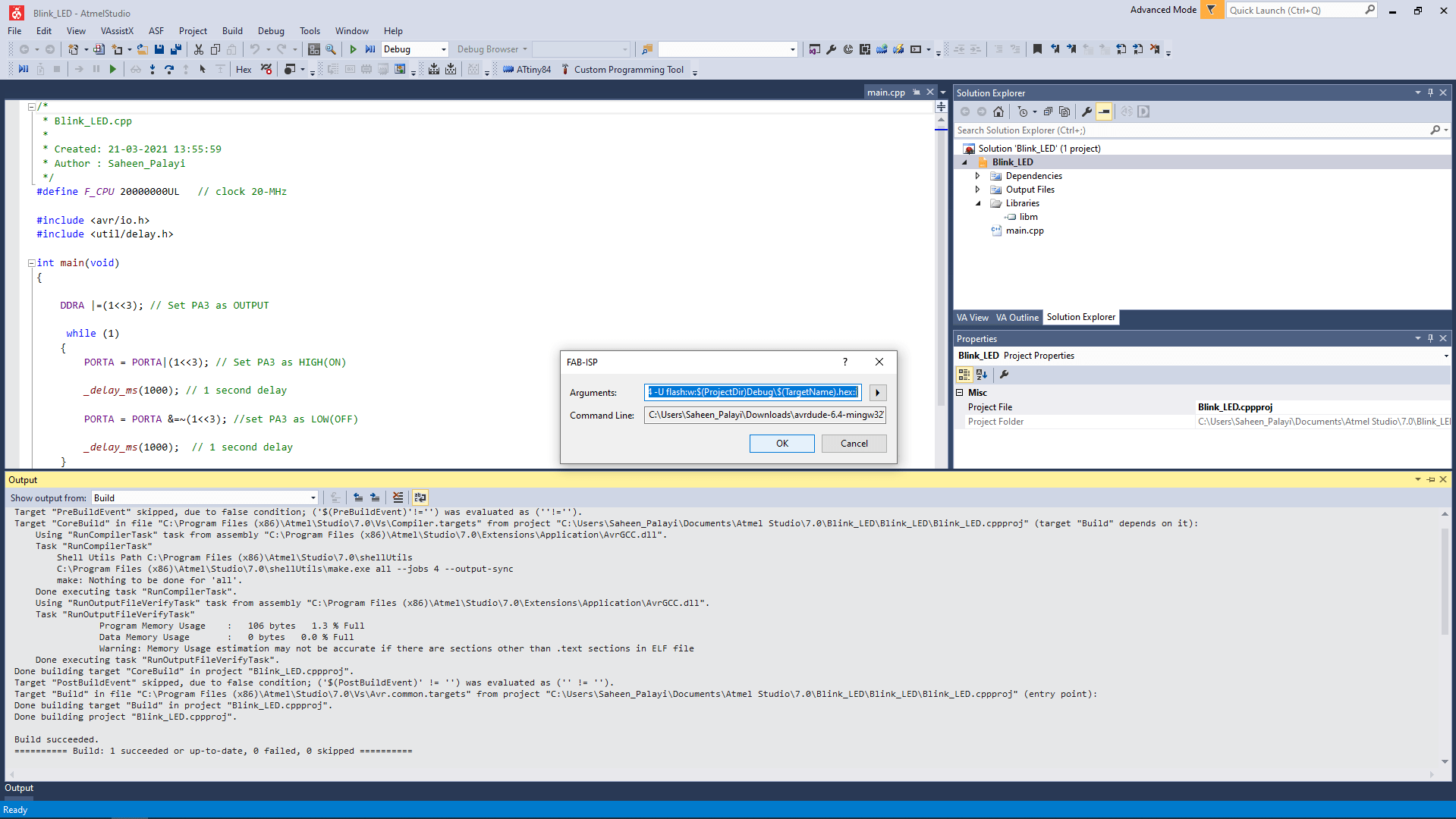
By following that a confirmation check window appeared with the Argument and command like clicked 'OK' to continue.
Then the LEDs on the ISP and the RGB LED (which sharing pins with same ISP pin of Attiny84) on the indicate while the flashing then immediately the blue LED which connected to PA3 is starts blink with 1 second delay.
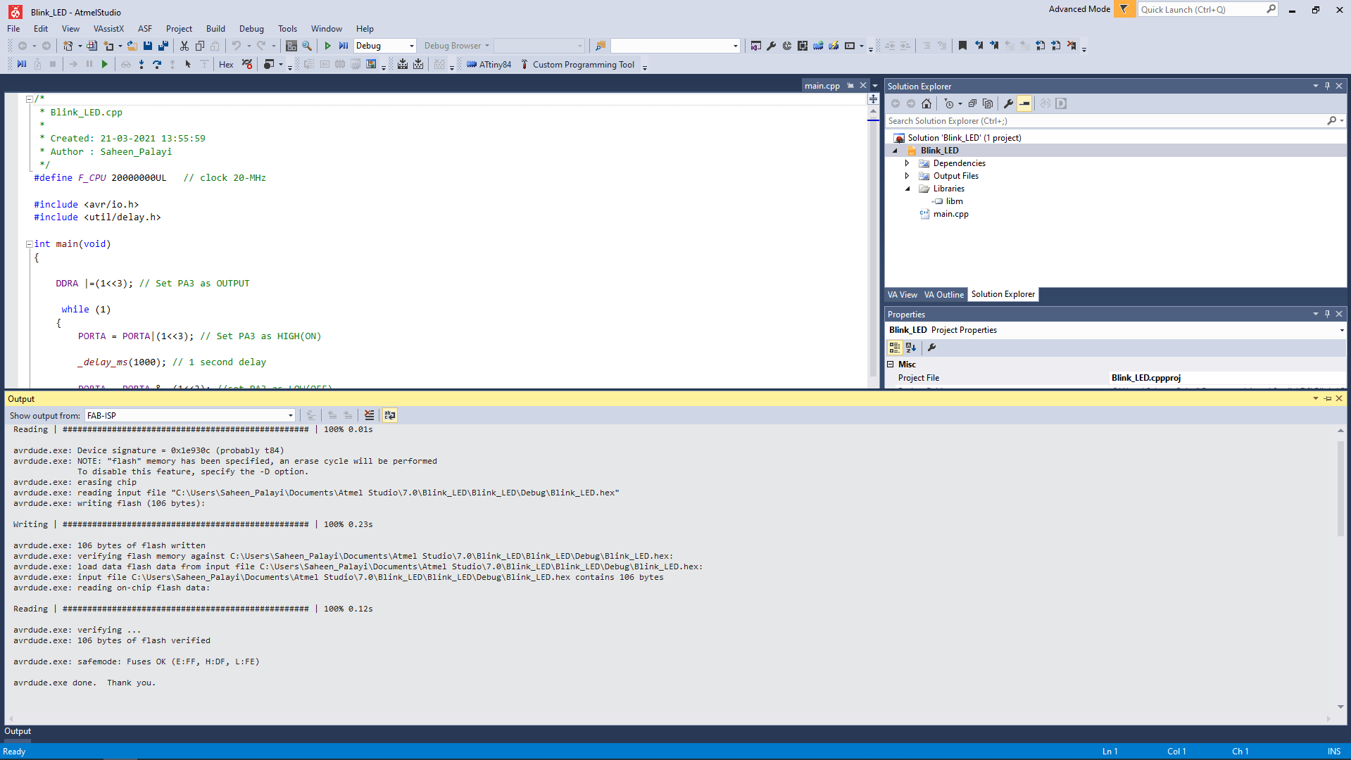
The flashing is done successfully! we can see the terminal messages in the Output section of Atmel studio. The High bright Blue LED is awesome.
Programing in Assembly
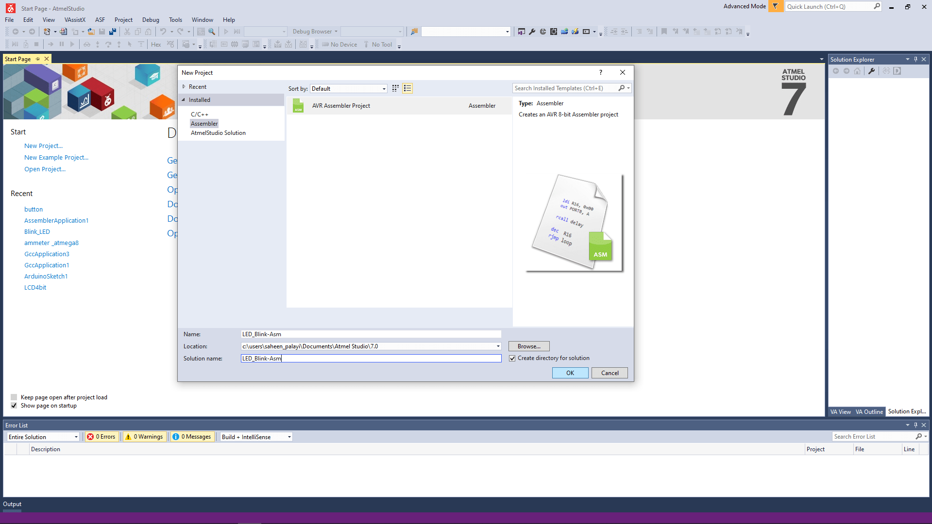
I opened a new project in Atmel studio and selected the assembler>>>AVR Assembler Project and gave a new name for the program and then followed everything I did before in Atmel studio to create the project.
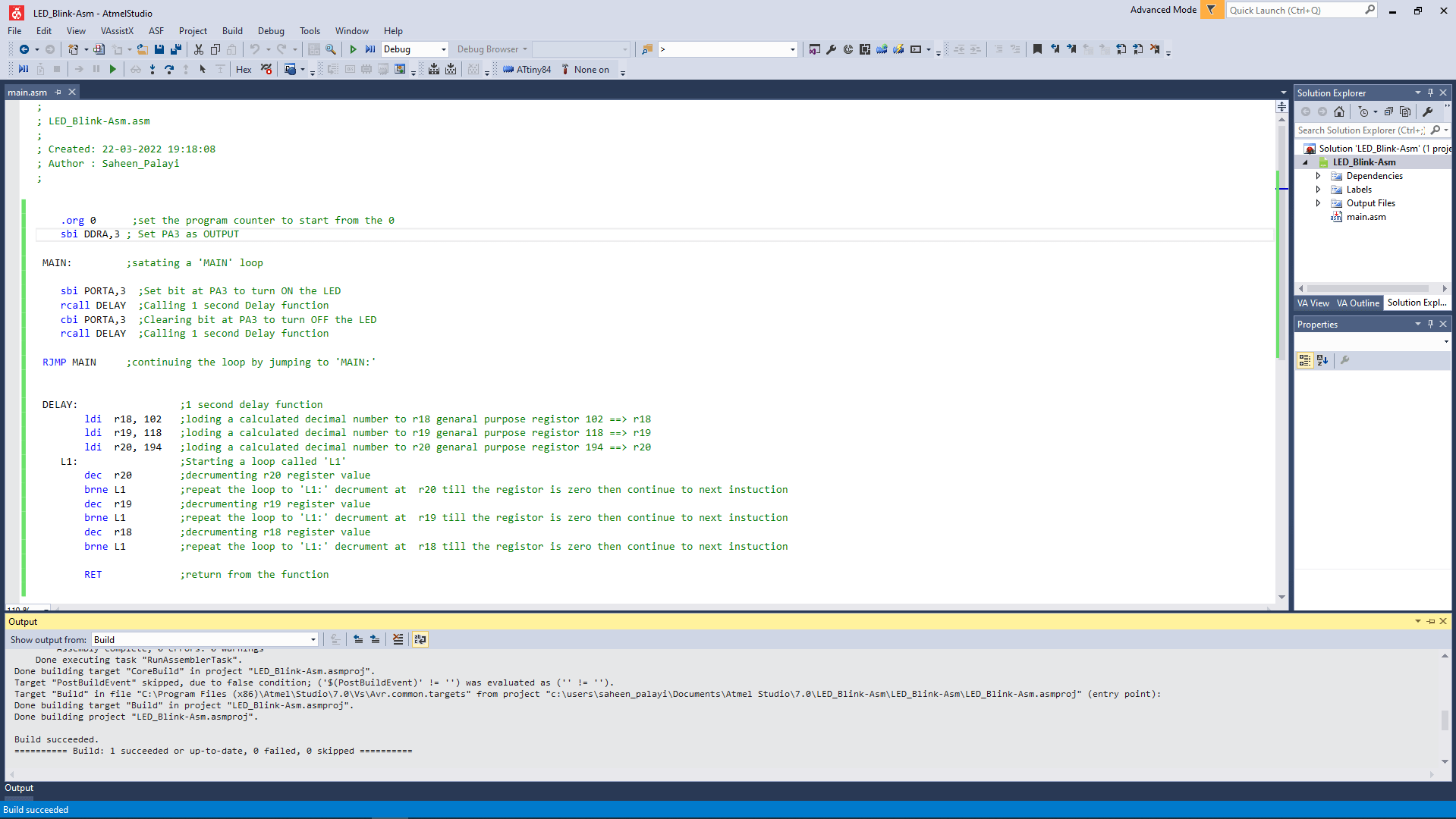
then I made code for blink that works. coding in assembly is something that we do at a low level programing so I already know the logics of the program and then I referred the Attiny84 Data sheet to find right Instructions for assembly programing.
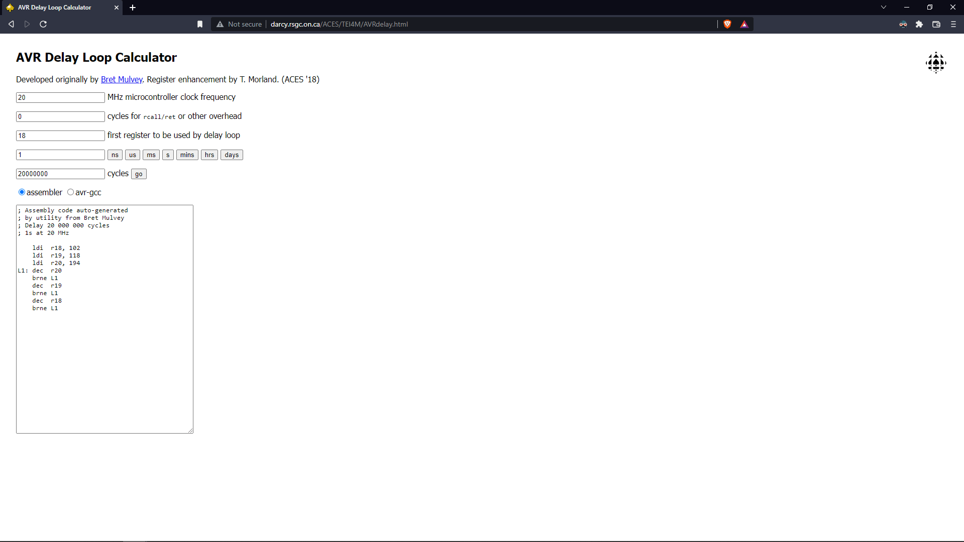
I used this AVR Delay Loop code generator to make the 1 second delay assembler program .please checkout the website here.
Here is the output of the program showing above video .And also changing the output LED to Red color by replacing 'PA3' to 'PA4'
week 8 Group assignment is to compare the performance and development workflows for other architectures
Other Architectures
For this week of group assignment at fabacademy we all together explore other Architectures and its development workflows.For exploring other architecture , we found out that we should try to use other development hardwares from our lab.So we got some Development hardware board from our Inventory and our instructors help us to get start with it.
- STM32 Nucleo Development Board
- ESP8266 NodeMCU Development Board
- ESP32 NodeMCU Development Board
- Raspberry PI (Microprocessor based single board PC)
- Lattice ICEstick Evaluation Board (FPGA Development board)
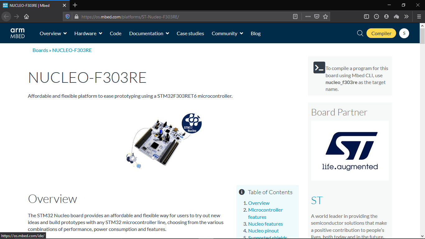
STM32 Nucleo
I selected STM32 for the experimental explorations.This works on ARM Architecture.FAB LAB Kochi has a hardware development board called STM32 Nucleo this board is based on a STM32 Series Chip from ST Microcontrollers for learning I just plugged the Nucleo Development board to the PC
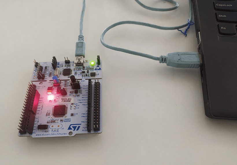
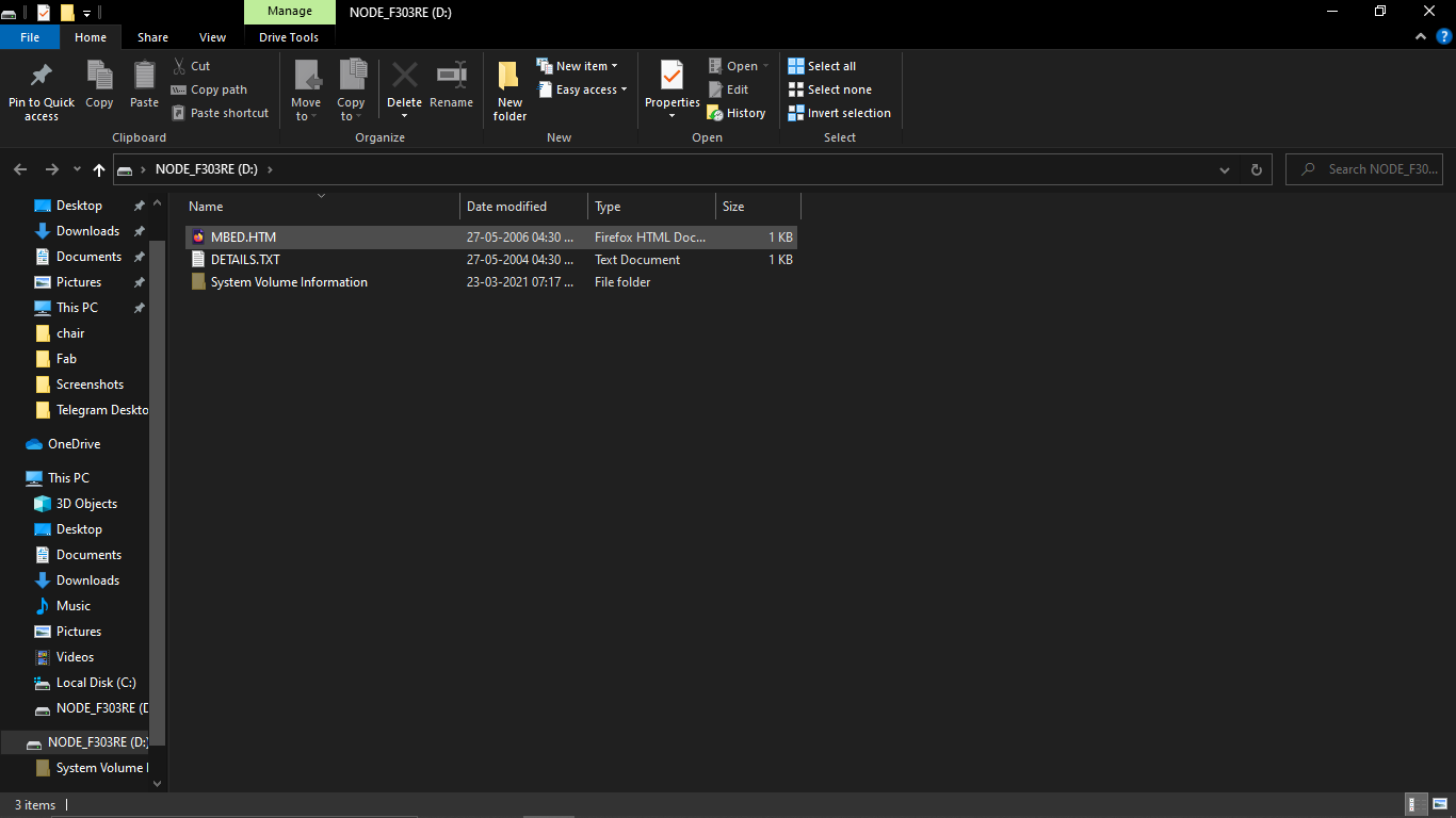
After plugged it opens a directory like a Flash drive .the directory contain an html file I thought may be its a tutorial
But it was like a login page into some kind of webapp,may be a online compiler .
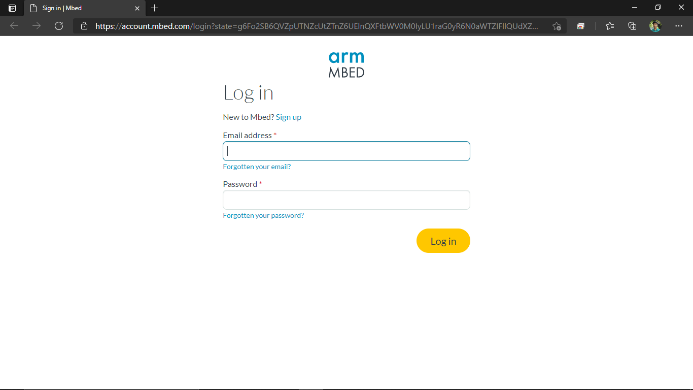
I sign up any way and by clicking sign up and filled all the information required then logged in to the web app after confirming the email the app is called Mbed OS
it opens a webpage which has information about the board and pin diagrams etc.....On the top corner I clicked on te compiler button that's open a new web app in new tab
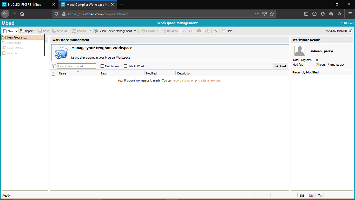
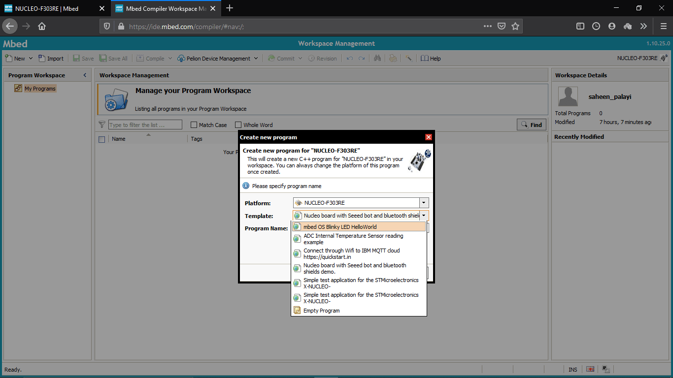
Then opened new Program under the 'New' tab and selected a by default blink test program
Then hit ok The program opened .cpp file its in C++ and I double clicked the .cpp file
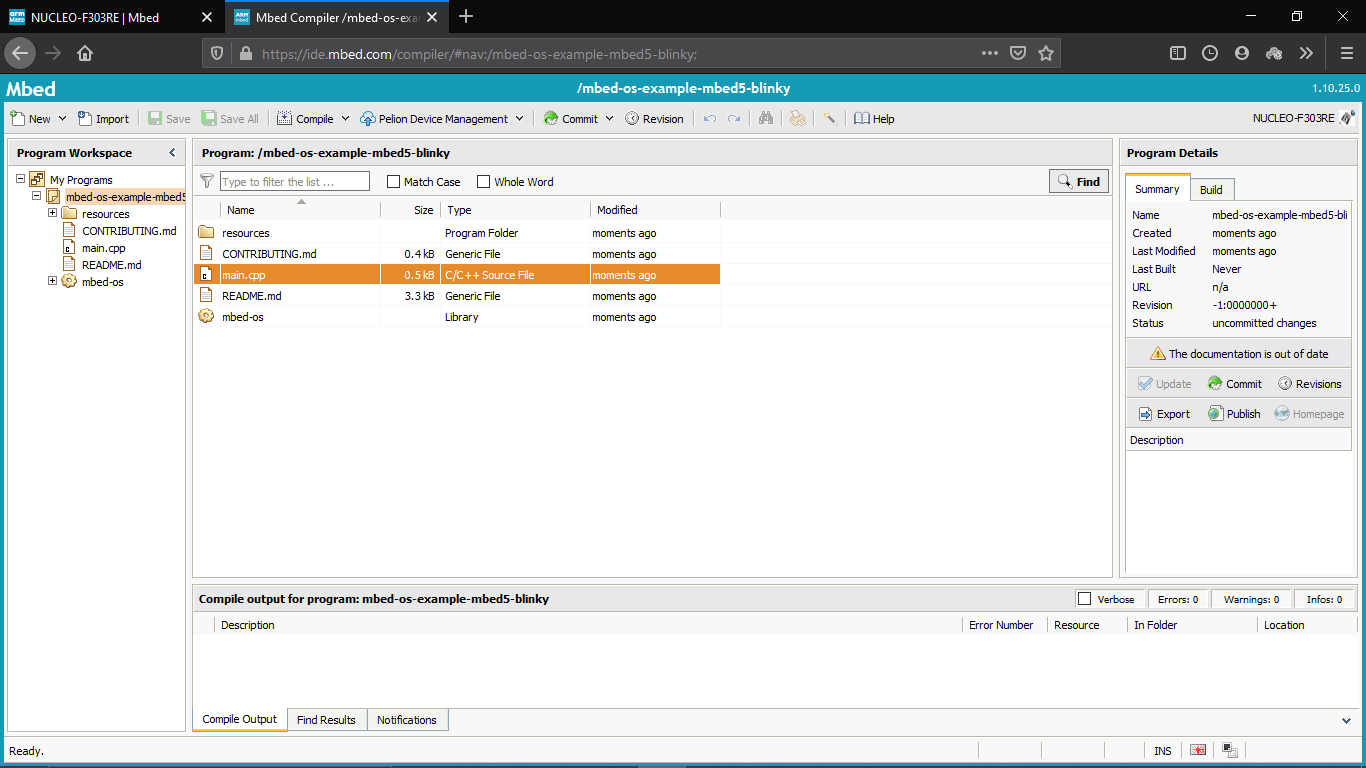
The cpp file is opened which contains the basic LED blinking The LD2 is on board led
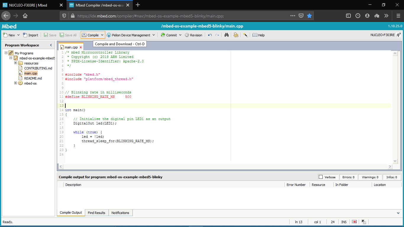
Then I just compiled the program by clicking te compile button on the menu tab
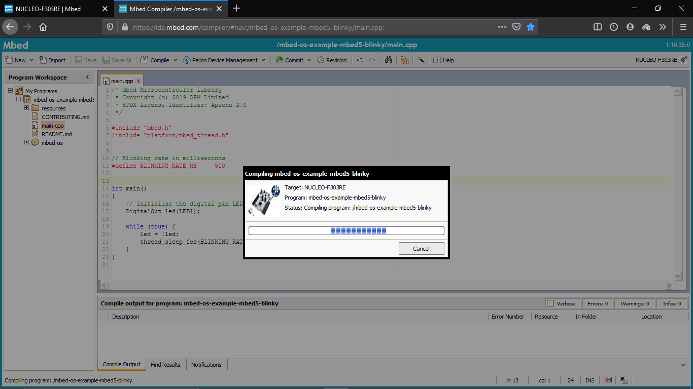
The it started to compile the program and then downloaded a bin file as the result
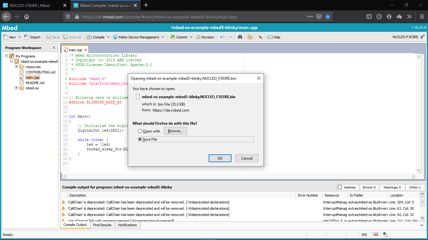
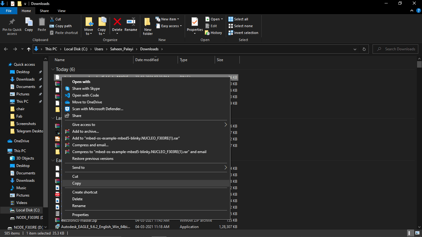
Then I saved the .bin file and copied the .bin file to the flash directory of the Nucleo development board
then I checked the board ,but it's not blinking anything!! . it's like no response.so I search for tutorials on YouTube and find out one embed os web app tutorial.It seems I did everything same but didn't work anyway I decided to go with other tutorial to try other ways to programing the board .I found another good tutorial by digikey It was awesome and I followed the video and downloaded the programing software they suggested
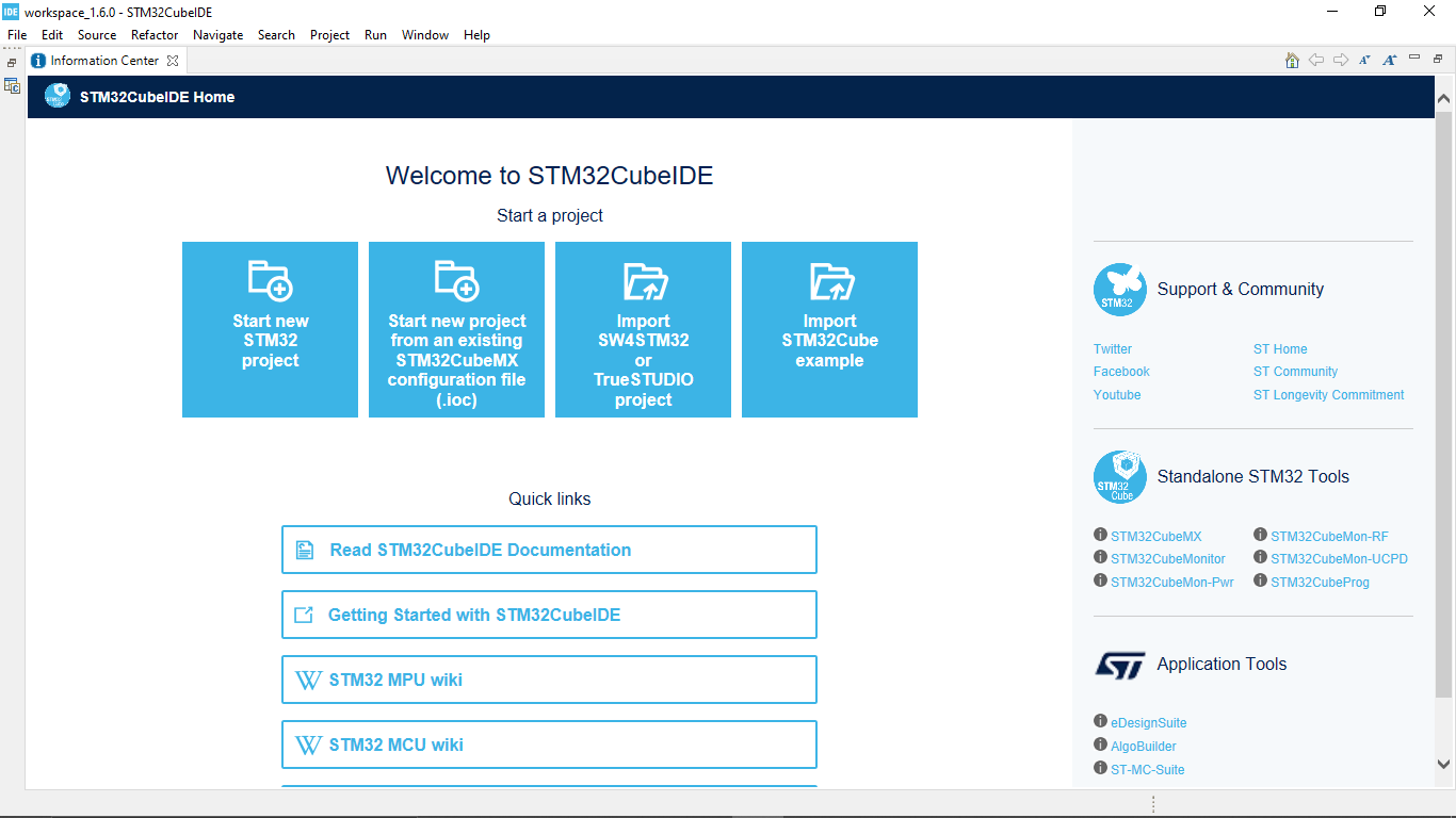
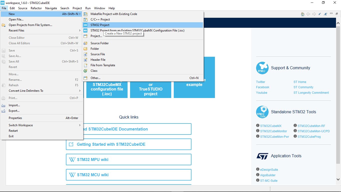
After installing the IDE I opened the STM32 cube IDE and created a new stm32 project by following file>>new>>STM32Project
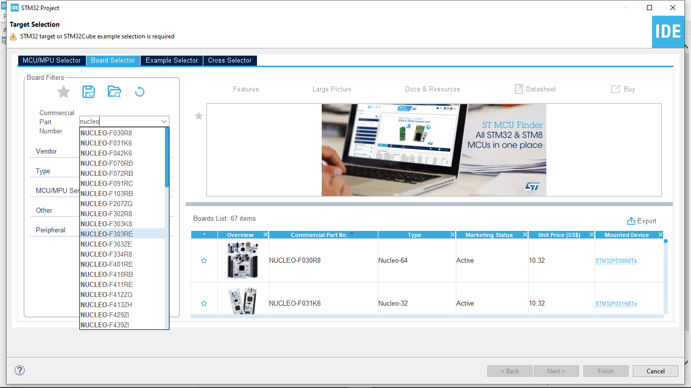
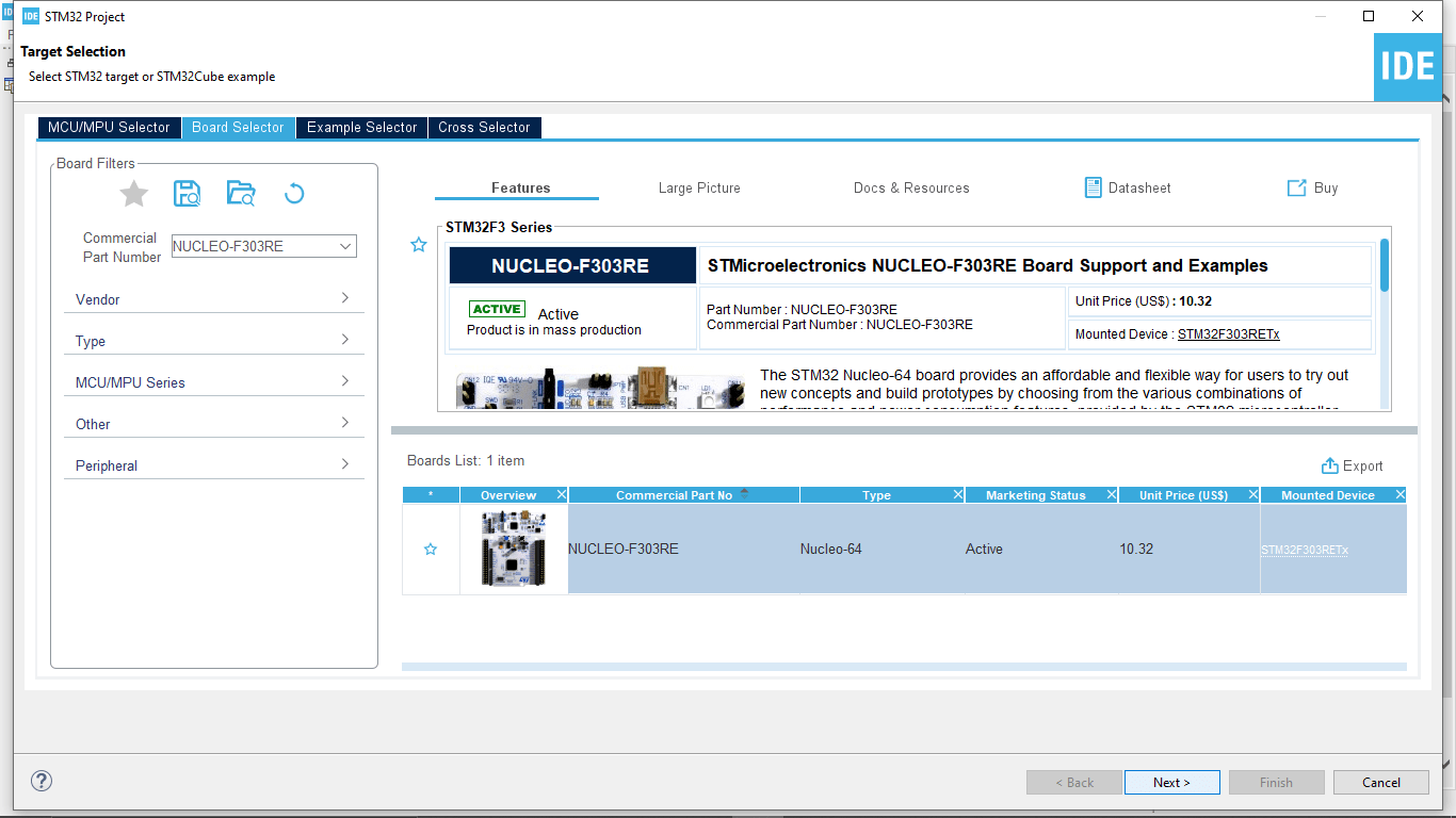
Then I selected the target as NUCLEO-F303RE board on the board selector tab
That shows a picture of the board that I'm using and clicked on it and clicked on the next button
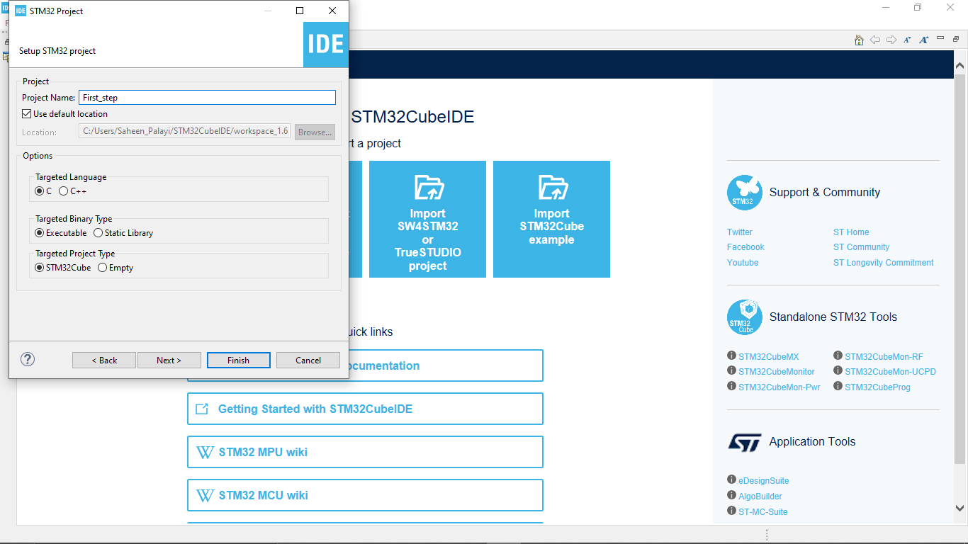
Then i given a project name as 'First_step' and selected the targeted language as 'C' language then clicked finish
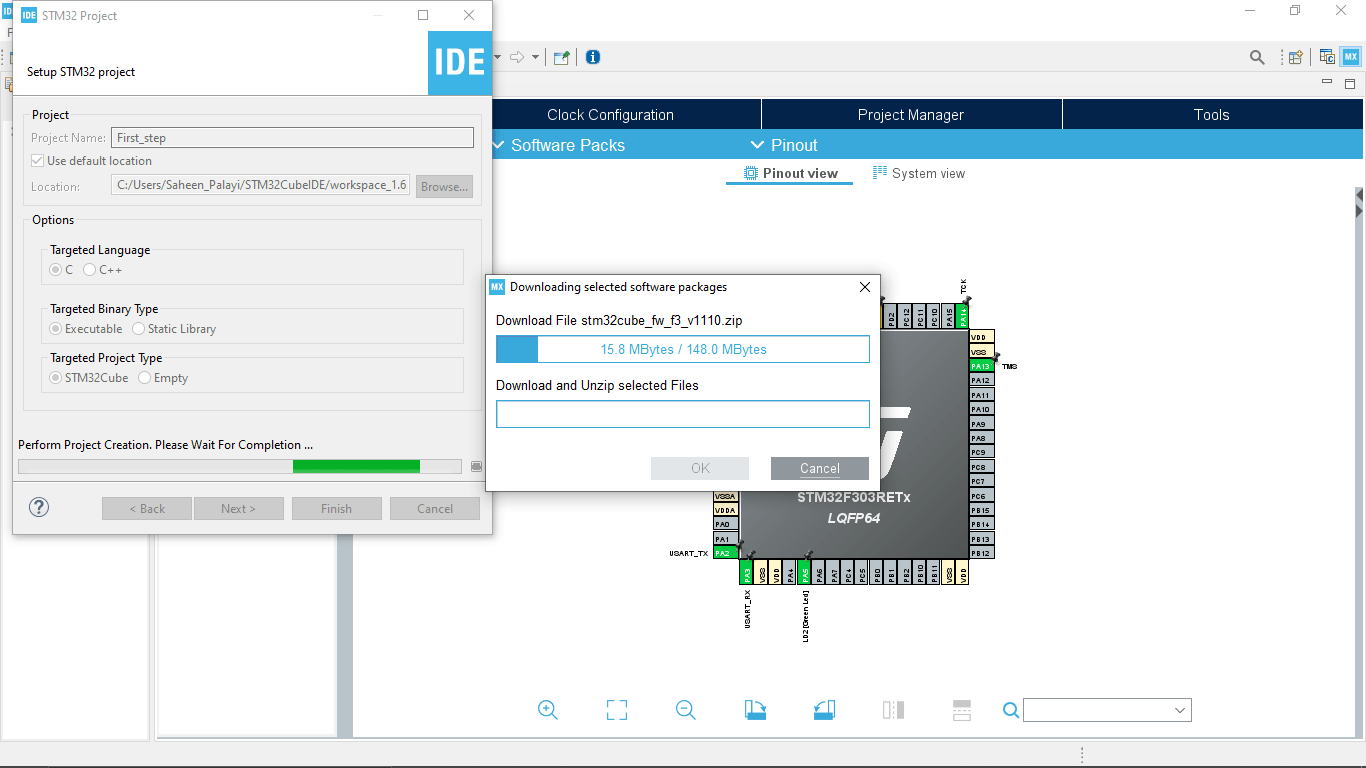
Then the IDE starts to download some resource files from the internet for the NUCLEO-F303RE development board
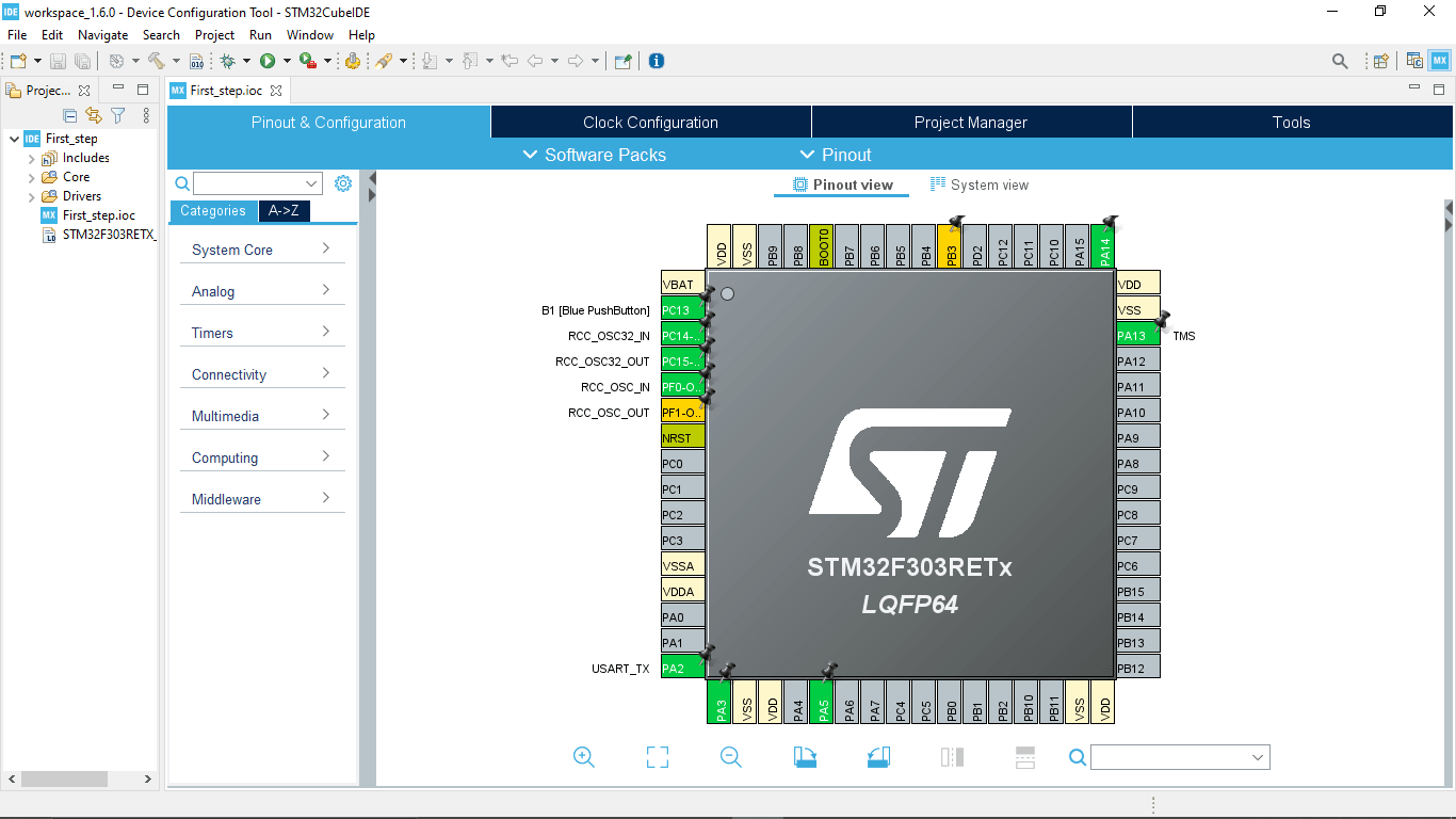
After the downloading the Project window opened and also shows the graphical pin diagram of the STM32 Microcontroller of the NUCLEO-F303RE board
We can Also see the set-up diagram of the stm32 nucleo-f303re development board under the clock configuration tab
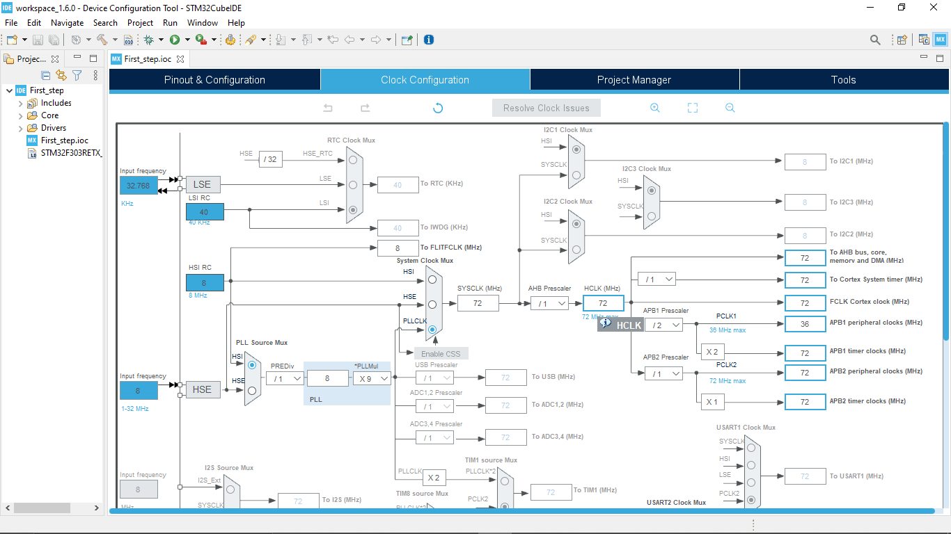
I don't need to change that.but if I making a custom board then I have change this accordingly
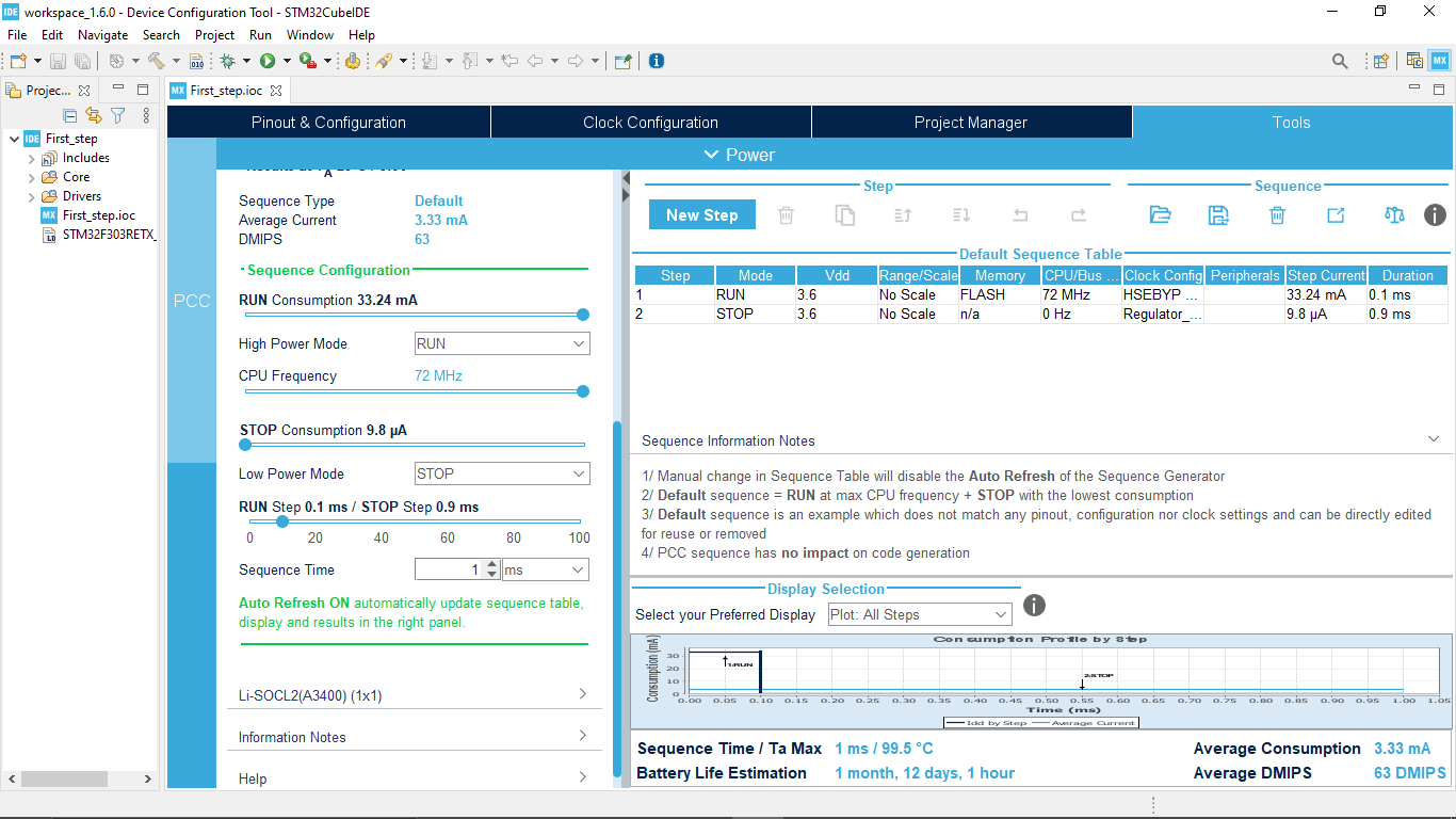
On the tool tab we can calculate current consumption of the Microcontroller,many other features are available too
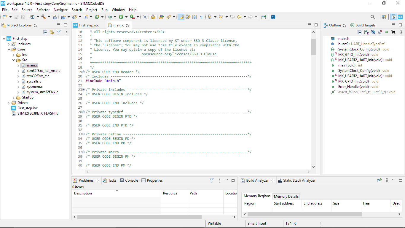
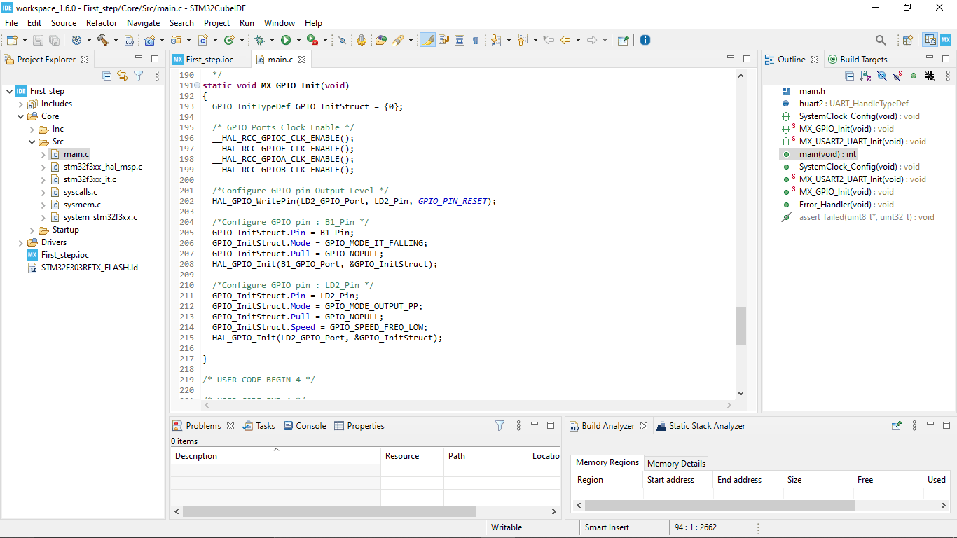
I opened the main.c file That I want work with by following First_step>>Core>>src>>main.c on the left
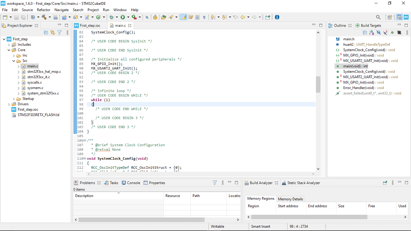
Scrolled down to find while loop to add my code in loop we can write what I want do with the Microcontroller
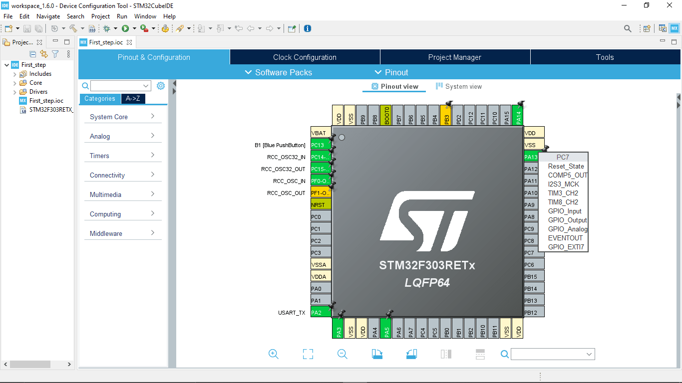
we can declare each IO pins as whatever we want with it on the graphical pin diagram by right clicking on the pins
while scrolling down we can also see how pins are declared in the program.the n I started to write the code for blinking the on board led by following the digikey tutorial.
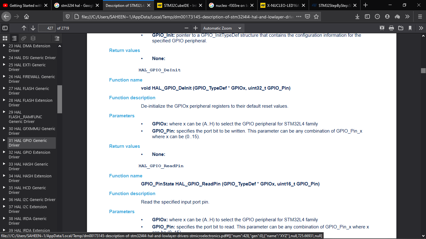
for finding the syntax I found the doc for stm32L4 by typing 'stm32l4 hal' on google will get this PDF doc I clicked on the GPIO gernric drivers and searches for the led toggle command,there is lot of commands are there for other applications
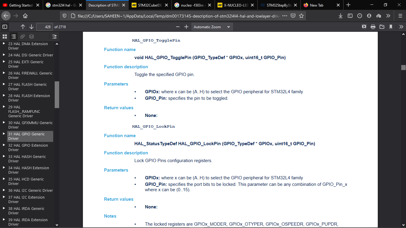
I found the Toggle pin command and entered the syntax in the code also a delay command.For toggle command it required two parameters 1)which PORT we are using then 2) which PIN we are using
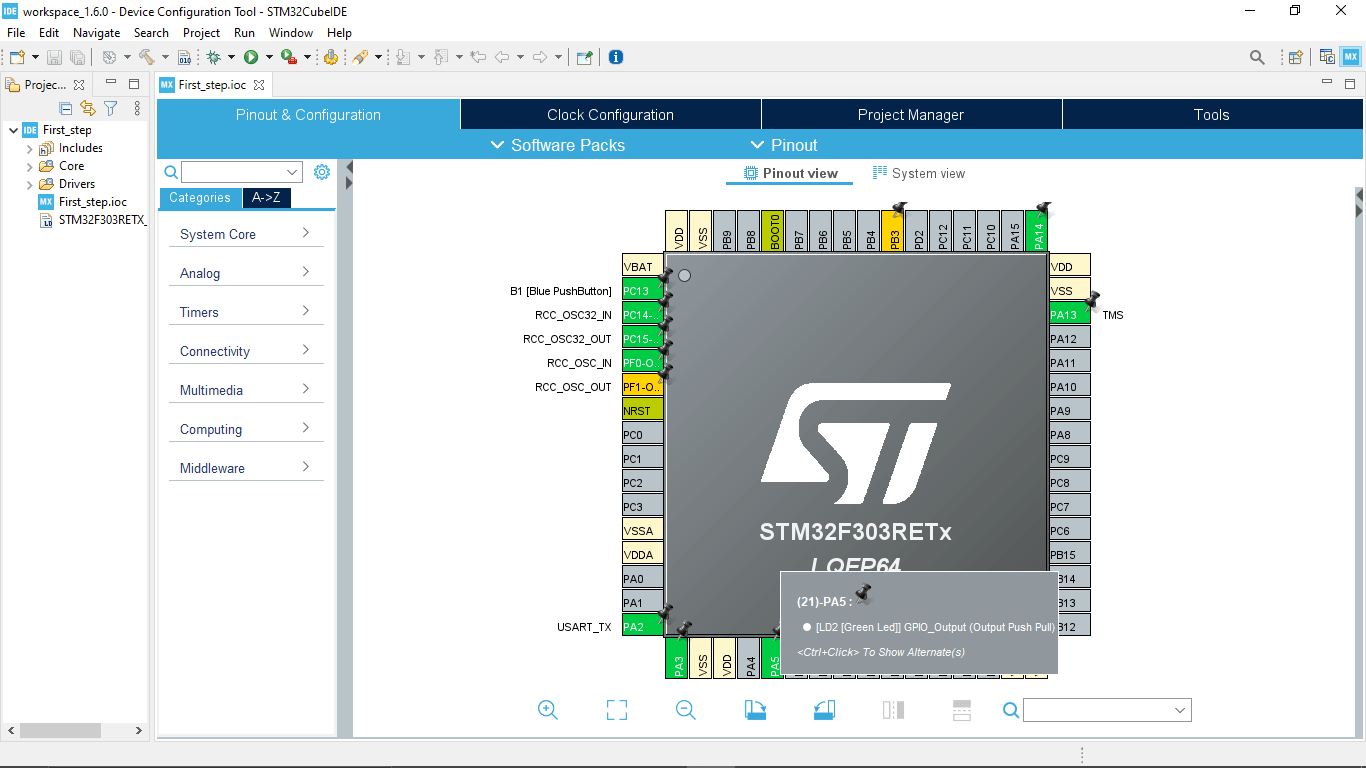
On the graphical PIN diagram we can see the LD2 LED connected to the GPIO_PIN_5 at POARTA (PA5)
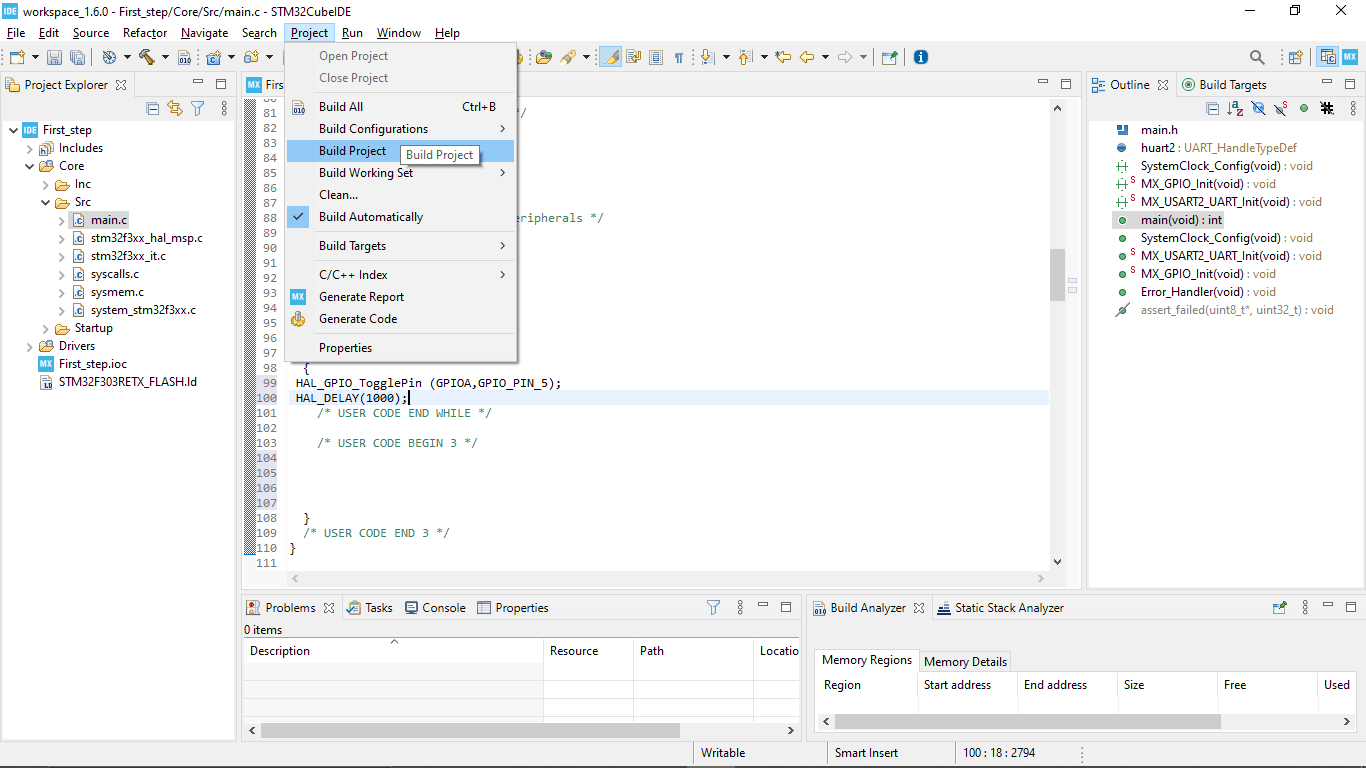
Then I build the program following Project>>Build but got an error and rebuilds again after fixing the error
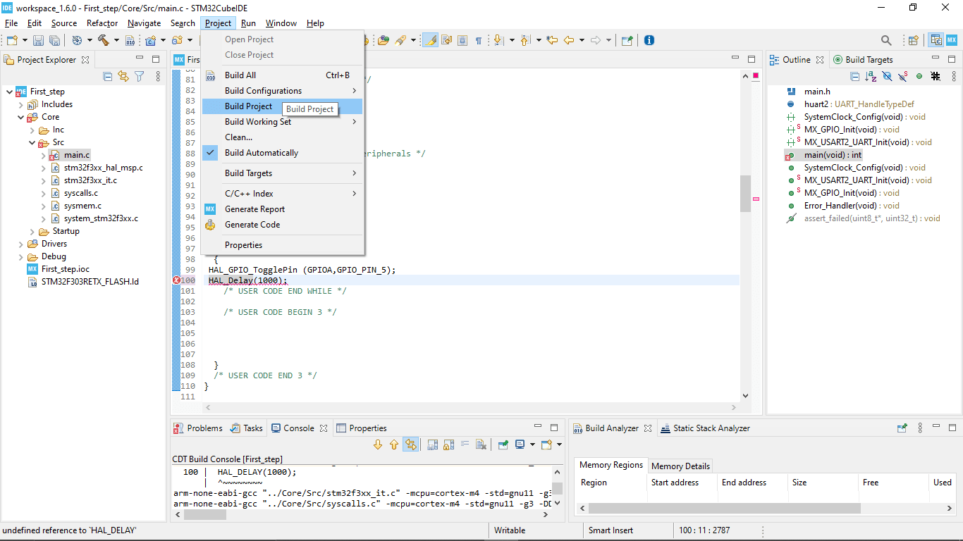
The while loop of the code that I created is given below
while (1)   //loop
      {
     HAL_GPIO_TogglePin (GPIOA,GPIO_PIN_5); //togling the LED LD2 Connected to the PIN 5
     HAL_Delay(1000);   // 1 second delay (1000ms = 1 sec)

     /*USER CODE END WHILE*/

     /*USER CODE BEGIN 3*/
      }
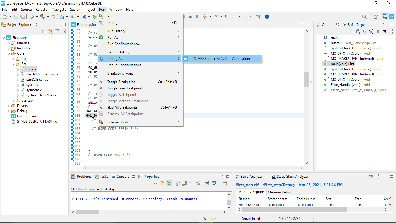
After the successful building ,to upload the program I clicked run>>Debug As>>STM32 Cortex-M C/C++ Application
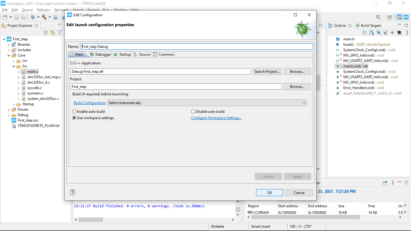
I leaves everything default on the De-Bug menu and clicked OK
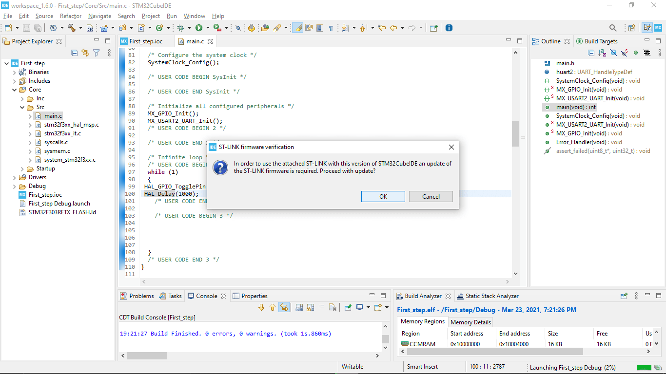
It STM32 Cube IDE automatically dedicated the NUCLEO-F303RE development board and says it's firmware need to be update
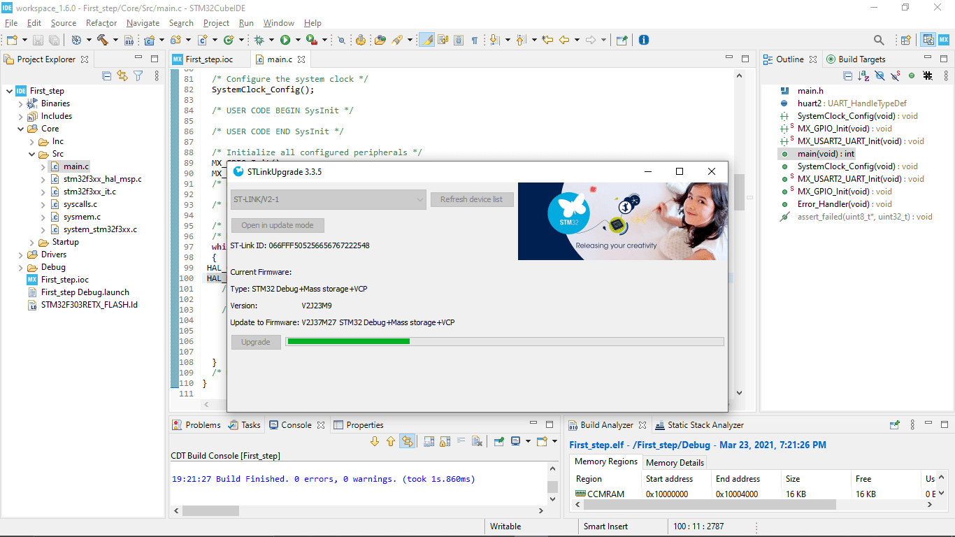
I clicked 'OK' then it started to update and after updating I decided to do the drag and drop programing that I tried before
It started to blink,So the firmware was the problem that's it didn't works earlier with embed Os programing method after the firmware updating program working fine.then I continue in the Cube IDE I run the program again
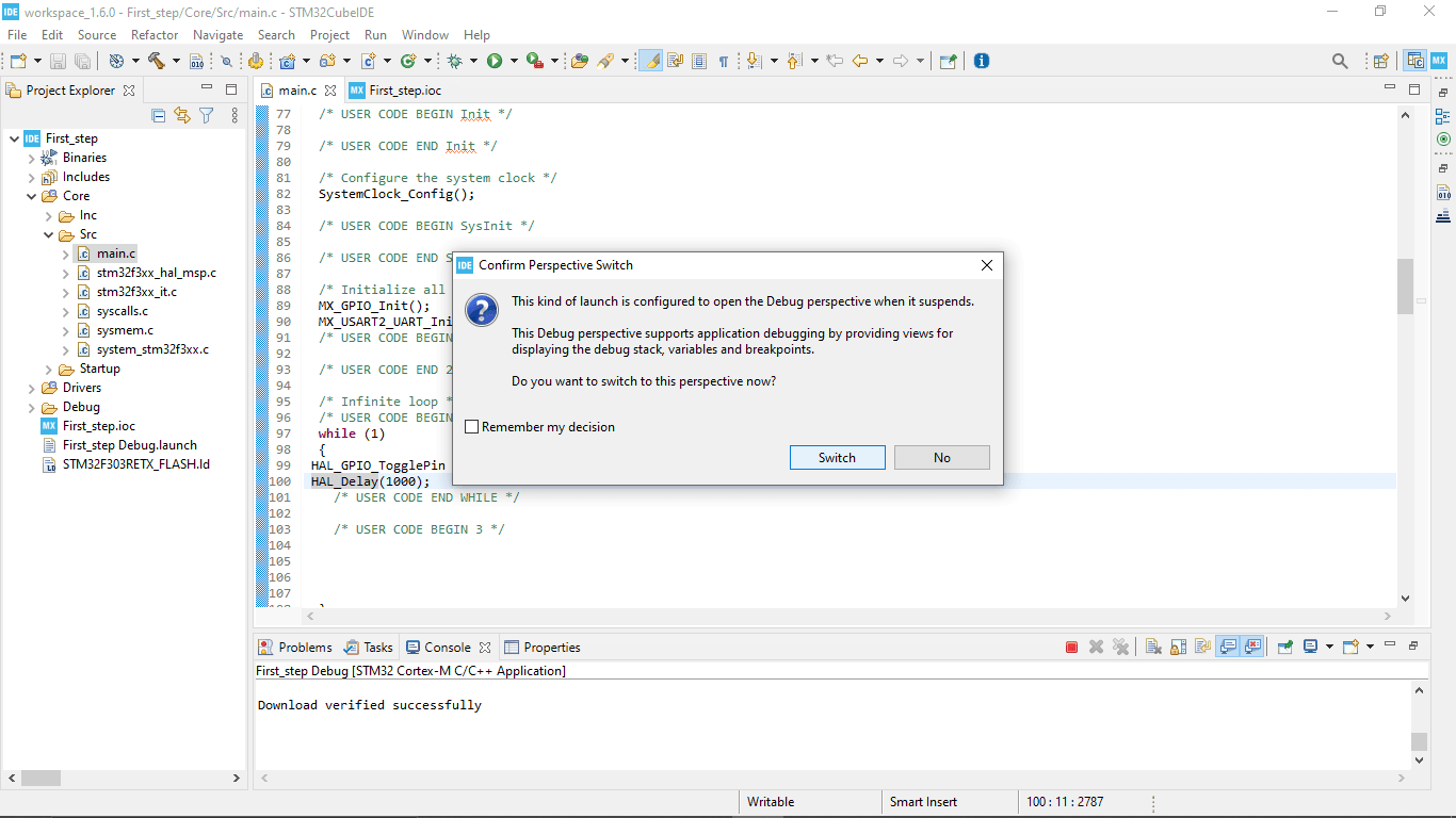
After downloading the program to the Board it asked to switch the debugging mode or not .I clicked OK to see the debugging process
In debug-mode we can see the RGB LED on the Debugging section blinking to indicate communication in between the Microcontroller and the cube-IDE
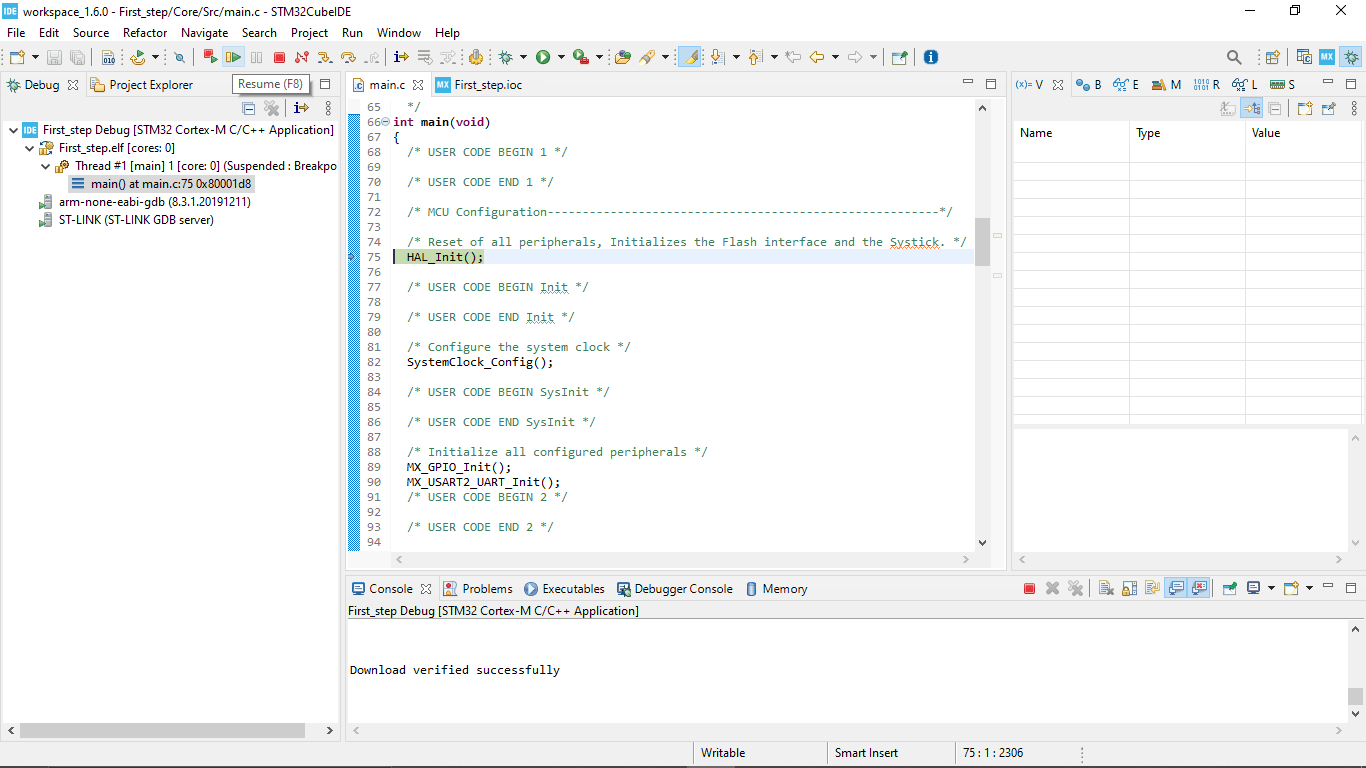
After Clicking the resume button the program will starts to run.We can pause the program and Can be execute step by step it was awesome
I did some adding and changes in the program for fast blinking in the cube ide.as per my experience the coding in STM32 Cube IDE is more simpler than the AVR Embedded C. I like it so Much
while (1)   //loop
                {
               HAL_GPIO_TogglePin (GPIOA,GPIO_PIN_5); //togling the LED LD2 Connected to the PIN 5
               HAL_Delay(1000);   // 100 milli second delay
               HAL_GPIO_TogglePin (GPIOA,GPIO_PIN_5);
               HAL_Delay(100);
               HAL_GPIO_TogglePin (GPIOA,GPIO_PIN_5);
               HAL_Delay(100);
               /*USER CODE END WHILE*/

               /*USER CODE BEGIN 3*/
                }
ESP8266
Esp8266 is a WIFI chip built for Iot applications by the chinese manufacturer Espressif Systems. And then they made it's own community by making it open source and cheap so people can buy and use them. So in this chip used a Tensilica L106 32-bit RISC processor based on Harvard architecture.
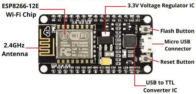
Here showing an open source development board that used the ESP8266 12E Module which is based ot rhe ESP8266 chip with a 4MB Flash ROM.The spec are given below
- Specifications
- Microcontroller Tensilica 32-bit RISC CPU Xtensa LX106
- Operating Voltage 3.3V
- RAM Bytes 256
- Input Voltage 7-12V
- Flash Memory 4 MB
- SRAM 64 KB
- Clock Speed 80 MHz
For more about the ESP32 Node-mcu exploration check Abhinav's Embedded week page.He did a lot of exploring on ESP8266 and also did use the board by trying some experiments.
ESP32
ESP 32 is a Powerful chip also from Espressif Systems and It has more clock speed and pins and other awesome feature than the other wifi chips.so It's suitable for various applications ranging from low-power sensor networks to the most demanding tasks, such as voice encoding, music streaming and MP3 decoding
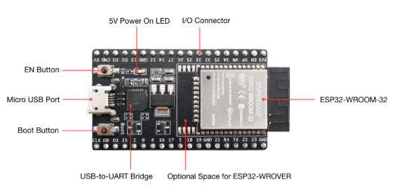
- Specifications
- Single or Dual-Core 32-bit LX6 Microprocessor with clock frequency up to 240 MHz.
- 520 KB of SRAM, 448 KB of ROM and 16 KB of RTC SRAM.
- Supports 802.11 b/g/n Wi-Fi connectivity with speeds up to 150 Mbps.
- Support for both Classic Bluetooth v4.2 and BLE specifications.
- 34 Programmable GPIOs.
- Up to 18 channels of 12-bit SAR ADC and 2 channels of 8-bit DAC
- Serial Connectivity include 4 x SPI, 2 x I2C, 2 x I2S, 3 x UART.
- Ethernet MAC for physical LAN Communication (requires external PHY).
- 1 Host controller for SD/SDIO/MMC and 1 Slave controller for SDIO/SPI.
- Motor PWM and up to 16-channels of LED PWM.
- Secure Boot and Flash Encryption.
- Cryptographic Hardware Acceleration for AES, Hash (SHA-2), RSA, ECC and RNG.
For more about the ESP32 Node-mcu exploration check Hanani's Embedded week page
Raspberry PI
Here Raspberry pi is not a Microcontroller. Instead, its a single board credit card sized mini computer that can do amazing things. We can attach keyboard ,mouse, Displays and etc.. just like our ordinary computers. And It's a good thing that the Raspberry Pi is open source and support linux based free Operating systems.
It runs on Broadcom ARM cortex-A72 processor from ARM architecture family.Apart from the processor it has RAM Memory card slots I/O ports(GPIO) that we can use just like a microcontroller but it's more powerful than that .
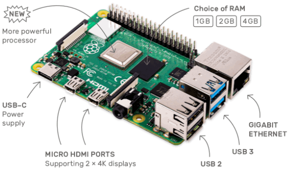
The above diagram shows the picture of a Raspberry PI 4 and its port details and The Specifications are shown below
- Specifications
- CPU Quad core Cortex-A72 (64-bit) @ 1.5GHz
- GPU H264 (1080p60 decode, 1080p30 encode) OpenGL ES 3.0 graphics, H.265 (4kp60 decode)
- RAM 1GB, 2GB, 4GB.
- Operating Voltage Range 5V with 3A minimum
- GPIO PORTS 28 I/O Pins
- LAN Available
- PoE Enable
- WIFI Available
- Bluetooth 5.0
- SD Card Available
- HDMI 2- Port with 4k Display (mini-HDMI)
- PWR Exp Header Not Available
- Power Source DC Power Jack, mini USB-C Port
- Expansion Connectors 40 Pins (SPI, I2C, LCD, UART, PWM, SDIO)
- USB 2×2.0, 2×3.0
- Camera CSI
- Display DSI
- Operating Temperature 0 – 50 degree
For more about the Raspberry pi exploration check Abel Tomy's Embedded week page
Lattice Ice-stick
Unlike other boards and microcontroller the Lattice Ice-stick works in different way , this development board comes with a Lattice ICE40HX1K FPGA chip.which means Field Programable array Chip. This means we can chose the inputs and outputs and other communication protocol for the chip our own by developing a HDL (Hardware Description Language) program to the chip as per our need.
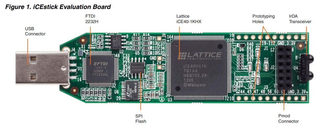
Pallab Shrestha was exploring the development board and he doesn't know anything about it actually because he is from a mechanical background.he failed to program the board but he explore well and Because of the time limitation we decided to move aside to explore in another time.
features
- High-performance, low-power iCE40HX1K FPGA
- FTDI 2232H USB device allows iCE device programming and UART interface to a PC
- Vishay TFDU4101 IrDA transceiver
- Five user LEDs
- 2 x 6 position Diligent PmodTM compatible connector enables many other peripheral connections
- Discera 12Mhz MEMS oscillator
- Micron 32Mbit N25Q32 SPI flash
- Supported by Lattice iCEcube2™ design software
- USB connector provides the power supply
- 16 LVCMOS/LVTTL (3.3V) digital I/O connections on 0.1” through-hole connections
For more about the ESP32 Node-mcu exploration check Pallab Shrestha's Embedded week page
Updates: Latter I've done my wild card week on the FPGA using the Lattice-Ice-stick Evaluation board check out my Week 15 to see more
References
- Fab Academy Embedded Programming classes
- microcontroller Documentation
- Difference Between Compiler Interpreter and Assembler
- Atmel Studio
- AVR dude for windows
- AVRdelay calculator
- STM32 Nucleo-64 development board
- arm MBED OS
Downloads
- Atmel Studio IDE files
- Group assignment STM32 Cube IDE files