Wildcard Week
week 15 Design and produce something with a digital fabrication process (incorporating computer-aided design and manufacturing) not covered in another assignment, documenting the requirements that My assignment meets, and including everything necessary to reproduce it
We are still under super lock down and the Lab is still not Opened.I like to do and document a Pick and Place Machining Process this week.But only possible after reopening the LAB.
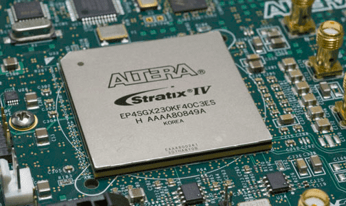
So when we all are left the LAB I was taken A Lattice ICE Evaluation Kit from the LAB to Explore more about it.so The Field Programable Gate Array or known as FPGA is another option to do this week.
The Field Programable Gate Array
The Field Programable Gate Array (FPGA )is a type Programable Chip Includes A large array of Logic Integrated Components that Let user to create their own Microcontroller or Processor for Multi tasking purposes
Software Installation
To program the Lattice ICE40 Evaluation kit development board we need a software SDK supports the board it also listed in the Lattice FPGA website
I found this lattice ICE40 software Installation tutorial video created by a guy name Dom from YouTube.According to Lattice Instructions I might need 3 software tools
- iCEcube2 FPGA Design Software. Click here to download
- Lattice Diamond Programmer Standalone. Click here to download
- A text editor I use VS Code
The above attached links will lead to the download page.Sign UP needed in order to download the tools.Available for both windows and Linux platforms.I downloaded for the Windows platform
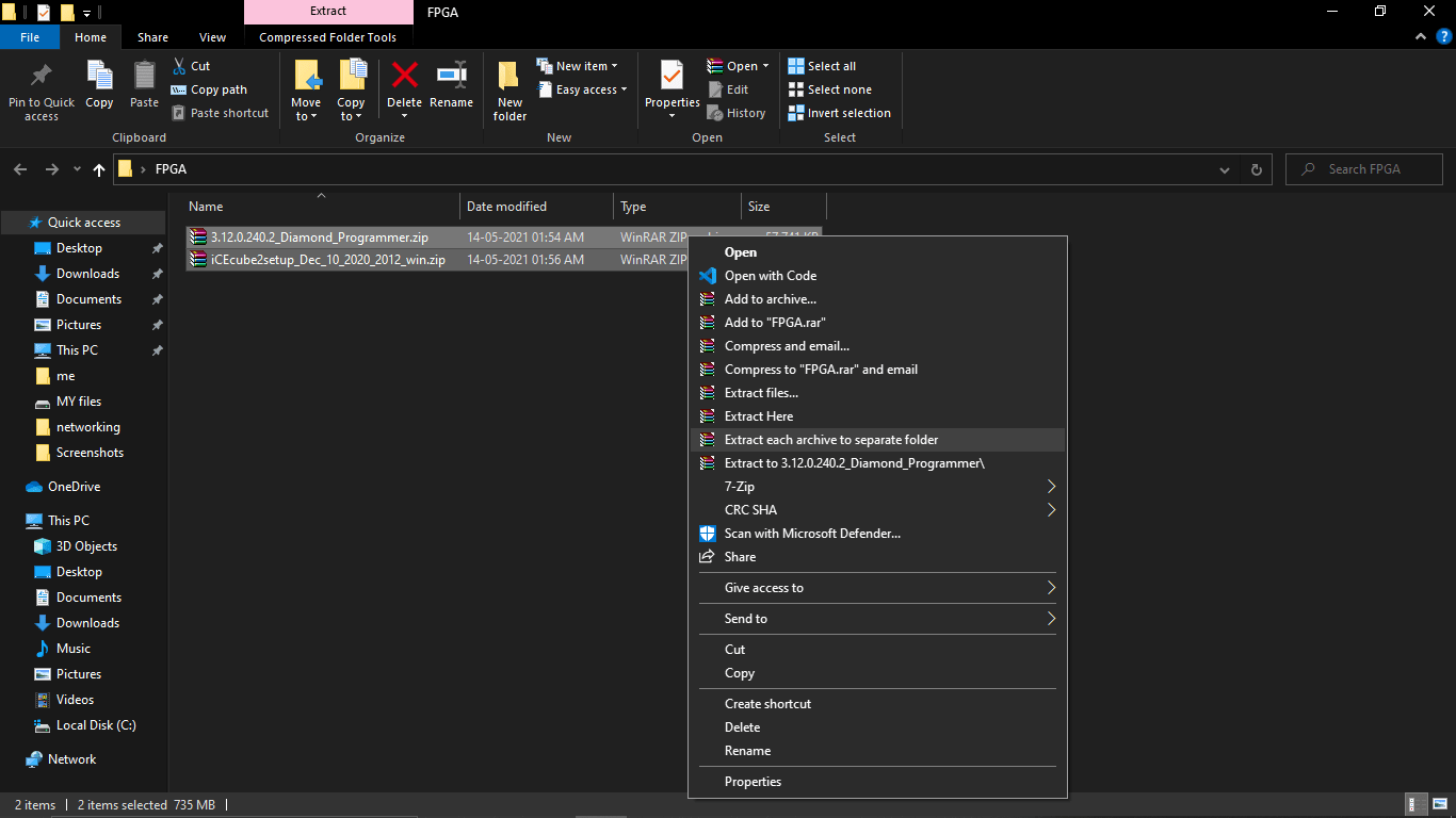
I created an FPGA directory on my Desktop and extracted the software tools then Started to install one by one
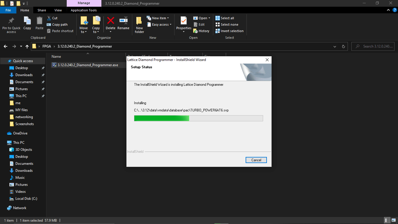
first I installed Lattice Diamond Programmer Standalone tool.This is used for detecting and programing the FPGA Chip
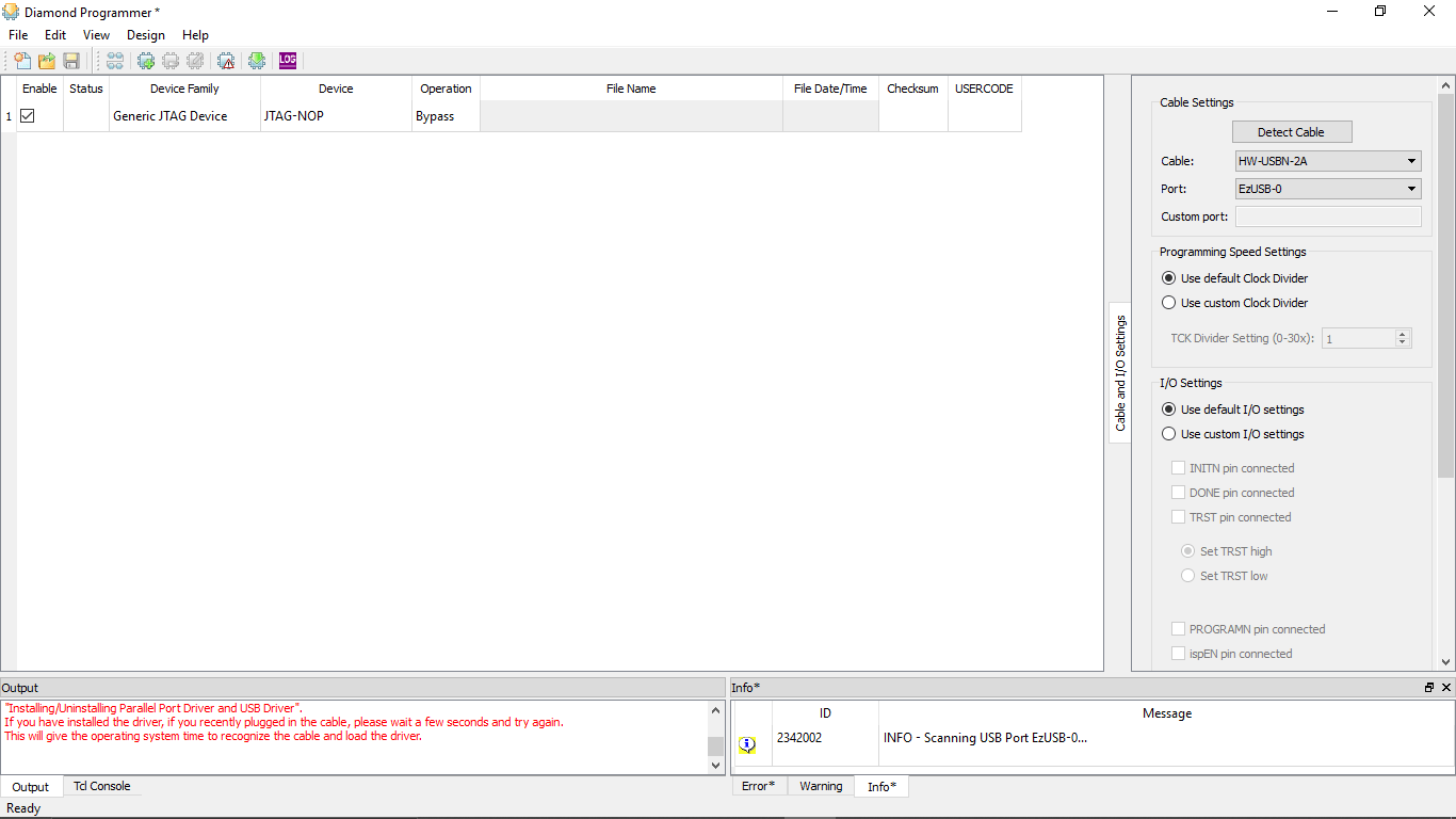
This is the Dimond Programer interface
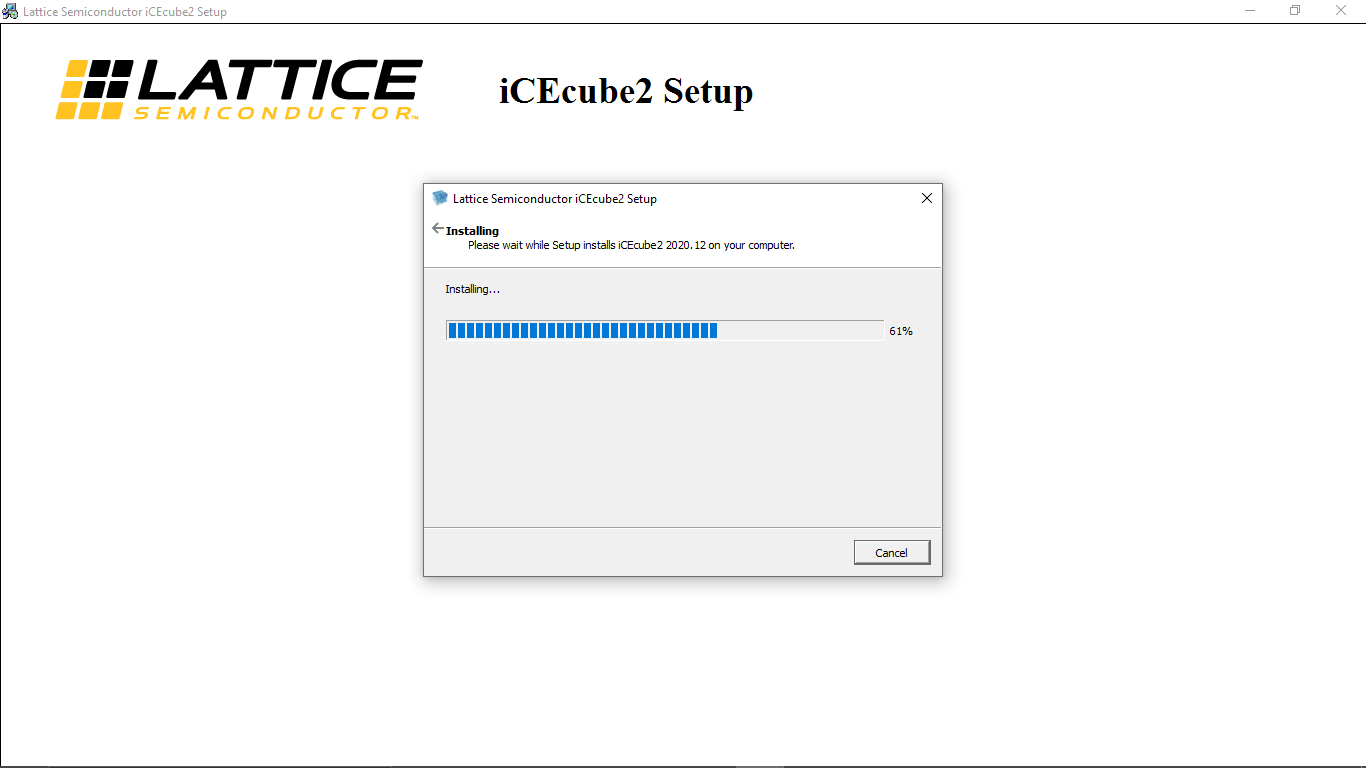
Then I installed iCEcube2 Design software.After the installation compete it shows an error
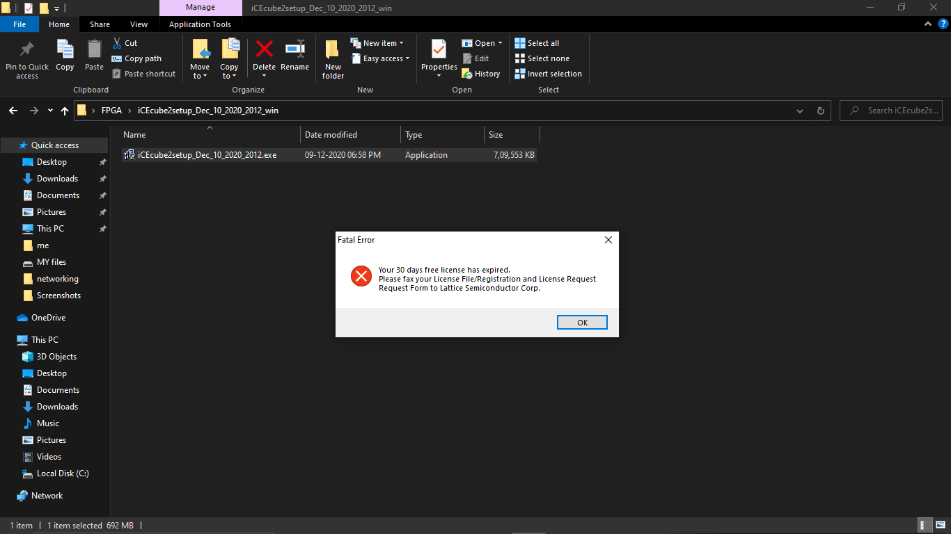
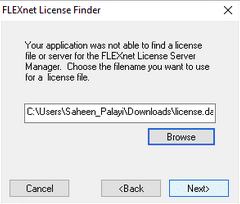
It says that "your 30 days free licence expired..." and also it's required a licence file .so I again logged to the latticesemi.com for thelicence
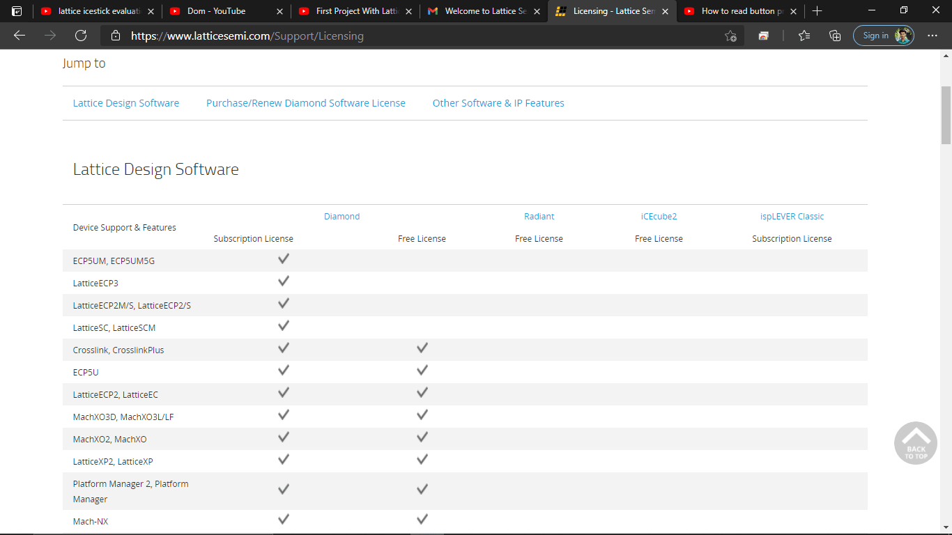
Lattice offering a free licence for iCEcube2 Design software so I followed the Instructions to get the licence file
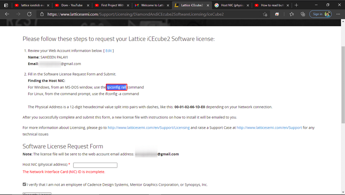
It required my computer Physical address for that I used this command in cmd to get the address like the lattice Instruction
ipconfig/all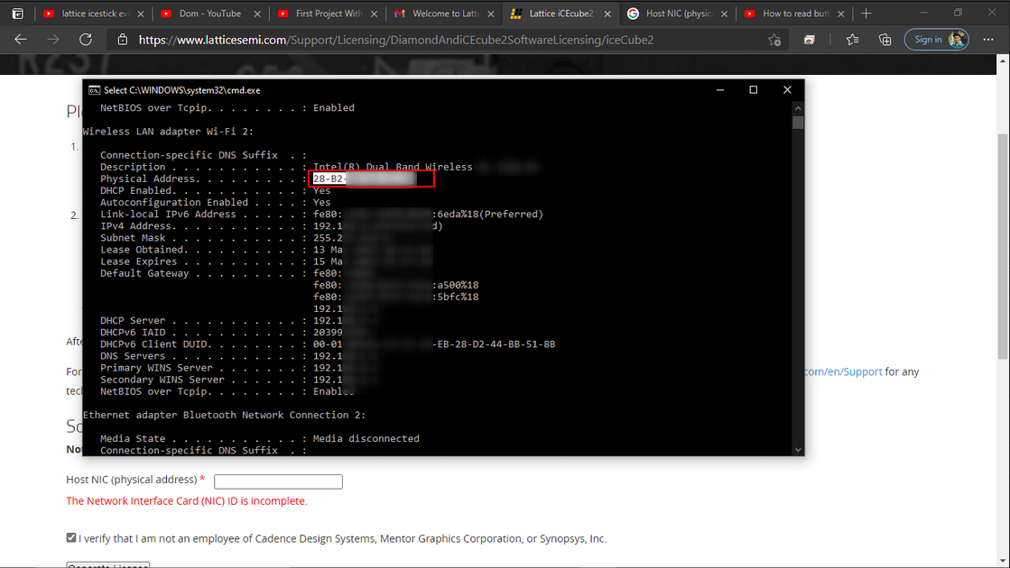
Then I copied the address code to the required input box on the latticesemi website
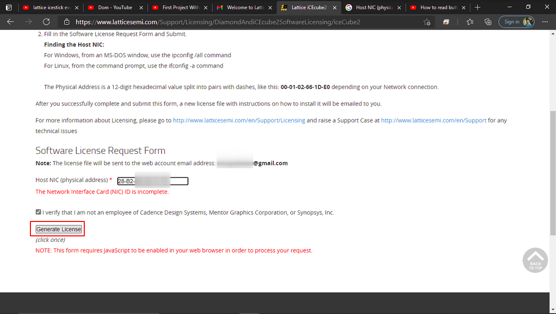
After I clicked generate option that sent me a file to my mail
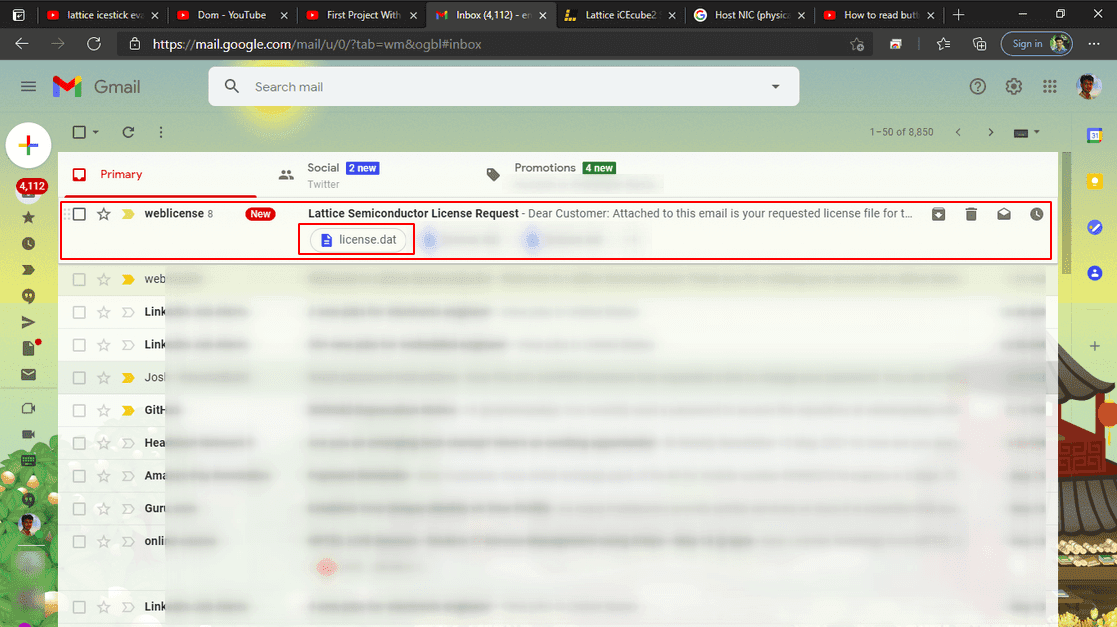
Then I downloaded the file and moved to the FPGA folder directory
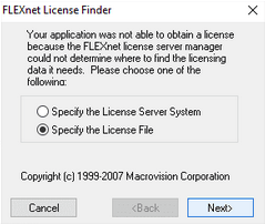
Then I tried to re-open the iCEcube2 software and shows it required a licence file I navigated to the folder directory
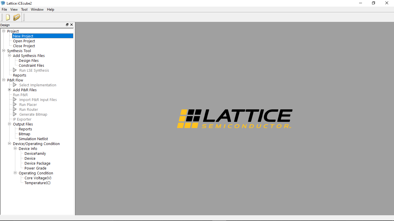
Then clicked finish and it Opens the iCEcube2 design software!
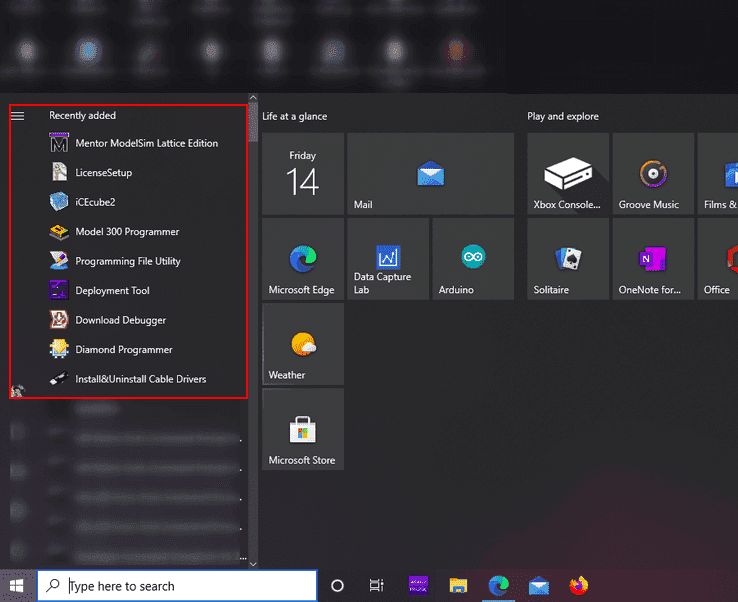
There are some extra softwares installed too.all come with the iCEcube2 installation pack
Still facing issues with the licence file getting error while opening the extra tools installed along with ICECube2
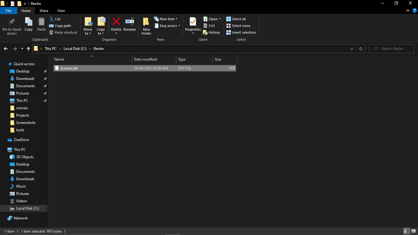
So I solved the problem by creating a folder called "flexlm" inside the C drive then moved the 'licence.dat' file in to it.
Let's Begin-NOT Gate in FPGA
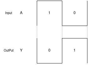
For the first project I decide to do a NOT gate on the Lattice ICEStick Evaluation board.So like I said logic gates are the basics of digital electronics.Here NOT gate is the simplest gate in logic gates
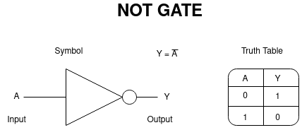
The above figure shows the symbol of the Not gate and also its input/output truth table.what ever value we gave to the in put,we get Negation of the input value at the out put.and of course there is only a '1' and a '0' in digital electronics
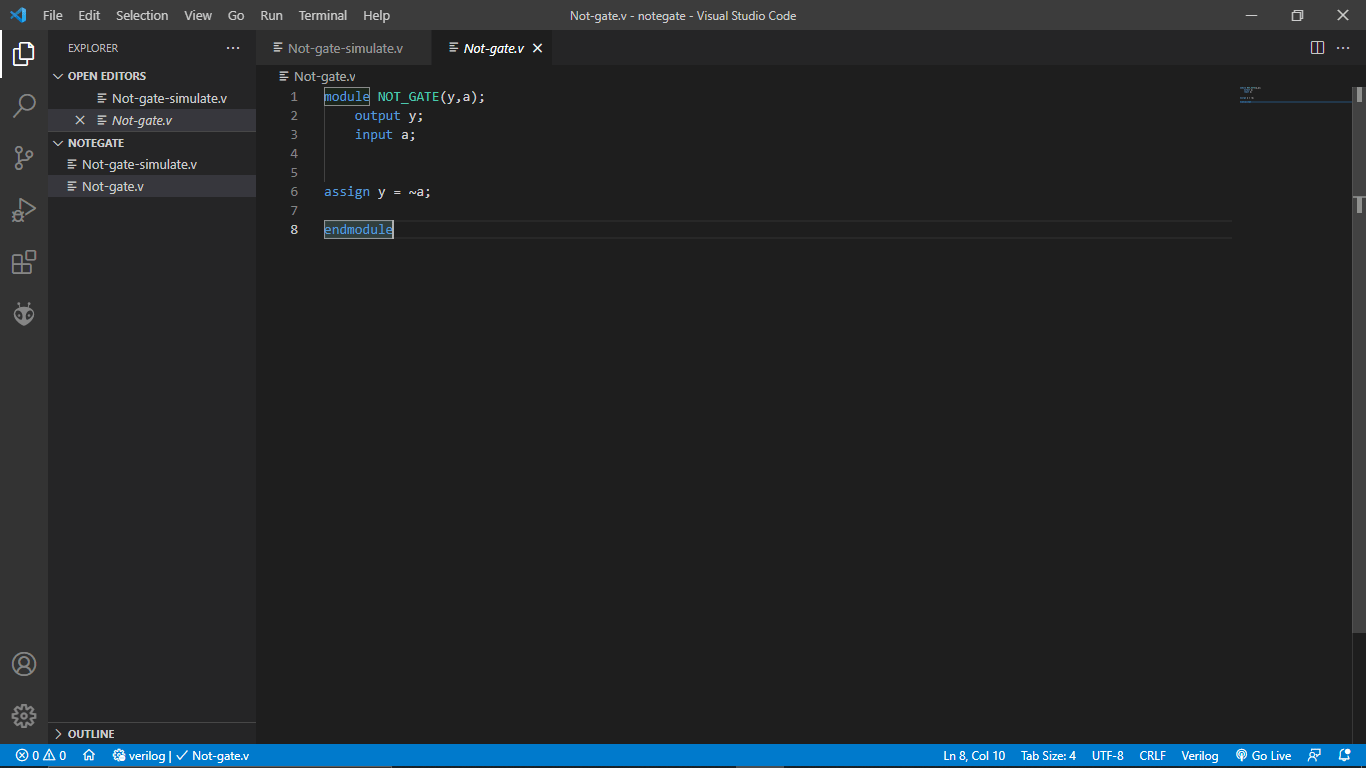
I created folder named NOTGATE inside my FPGA/Project Directory and Opened in VS Code editor.Then started to write the code for the NOT gate
    module NOT_GATE(y,a);
        output y;
        input a;


    assign y = ~a;

    endmodule
You can see from above figure I used this simple code in side the 'Not-gate.v' file ( '.v' stands for Verilog ).then I saved the file.
Then I opened the iCEcube2 FPGA Design software and double clicked on the 'New Project' option
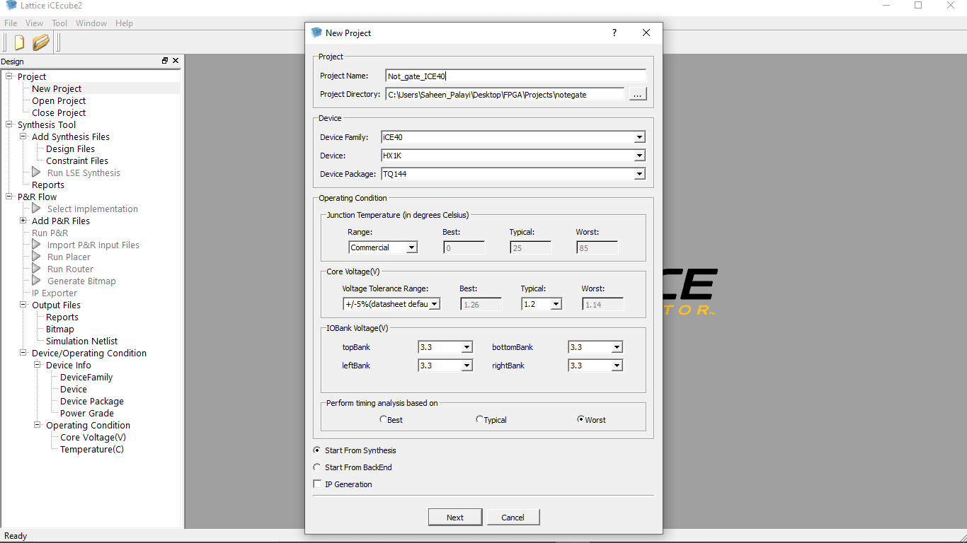
I gave a project Name 'Not_gate_ICE40' then liked the file directory of NOTGATE project That I already build .and given other required information ass well shown in the above figure .then clicked 'Next'
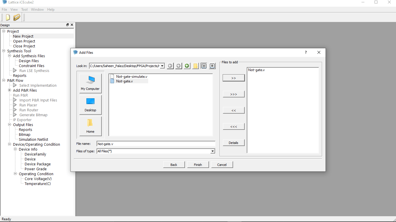
In the next window I added the Verilog program file by clicking the 'Add' button as shown as in the figure .then clicked finish
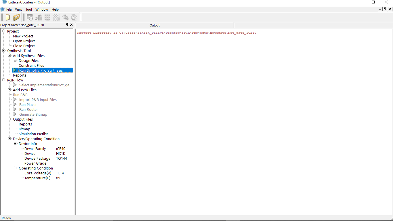
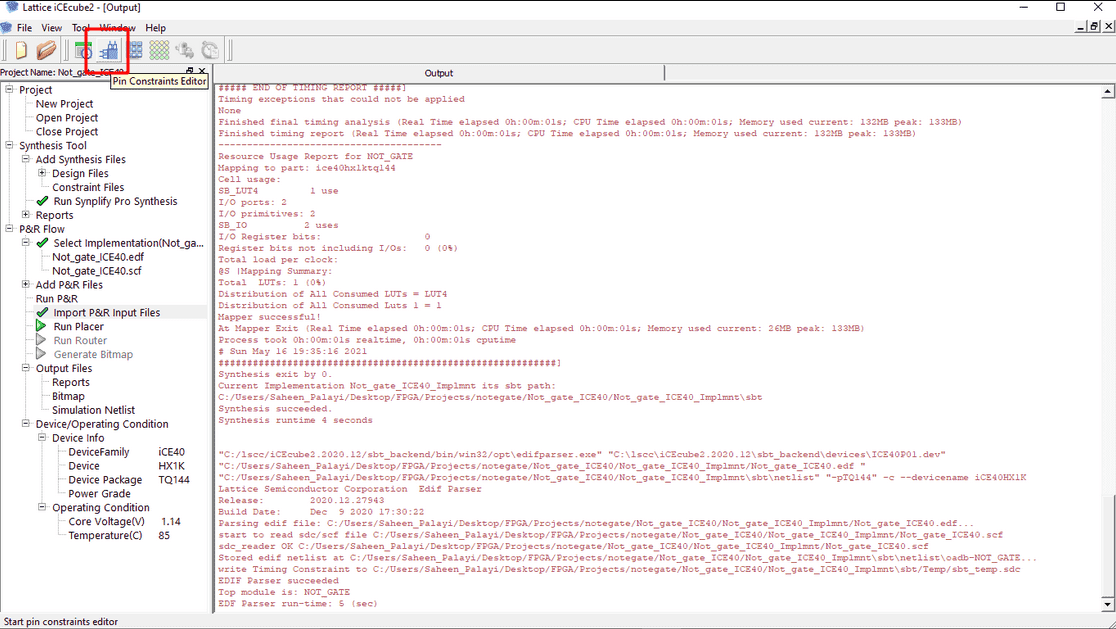
The project successfully created! now I need to compile te program that I added so double clicked on the 'Run Simplify Pro synthesis' option then it started to compile the code
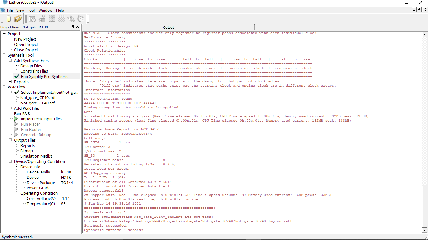
So the compilation successful! without any error You can see the log results on the window.Two file associated this project being created in side the iCEcube2 project folder.we can see that under the P&R Option on the iCEcube2 Software. This editor only used for compile and generate code we cant edit the program using iCEcube2
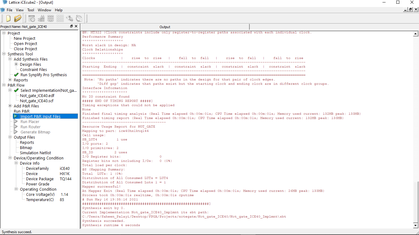
Then I double clicked on the "Import P&R Input Files" option from the left which import the files from thee directory for preparation of the bin file generation process
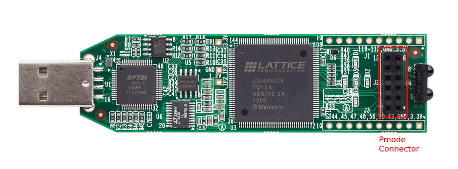
Now I need to set the pins for out put and the input.It has 5 on board LEDs,but doesn't have any onboard buttons .I'm decided to use this pins from the Pmode connector of the Lattice ICEStick Evaluation board for a button as an external input
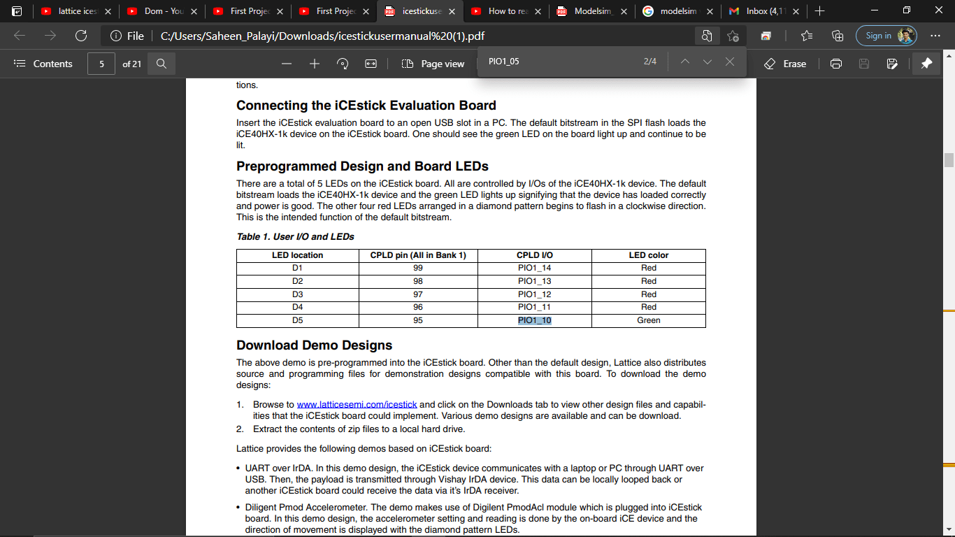
I found the PIN OUT information of ICEStick from the user guid.So I selected the green LED which connected to PIN number '95'.Also found the PIN OUTS of the Pmode connector
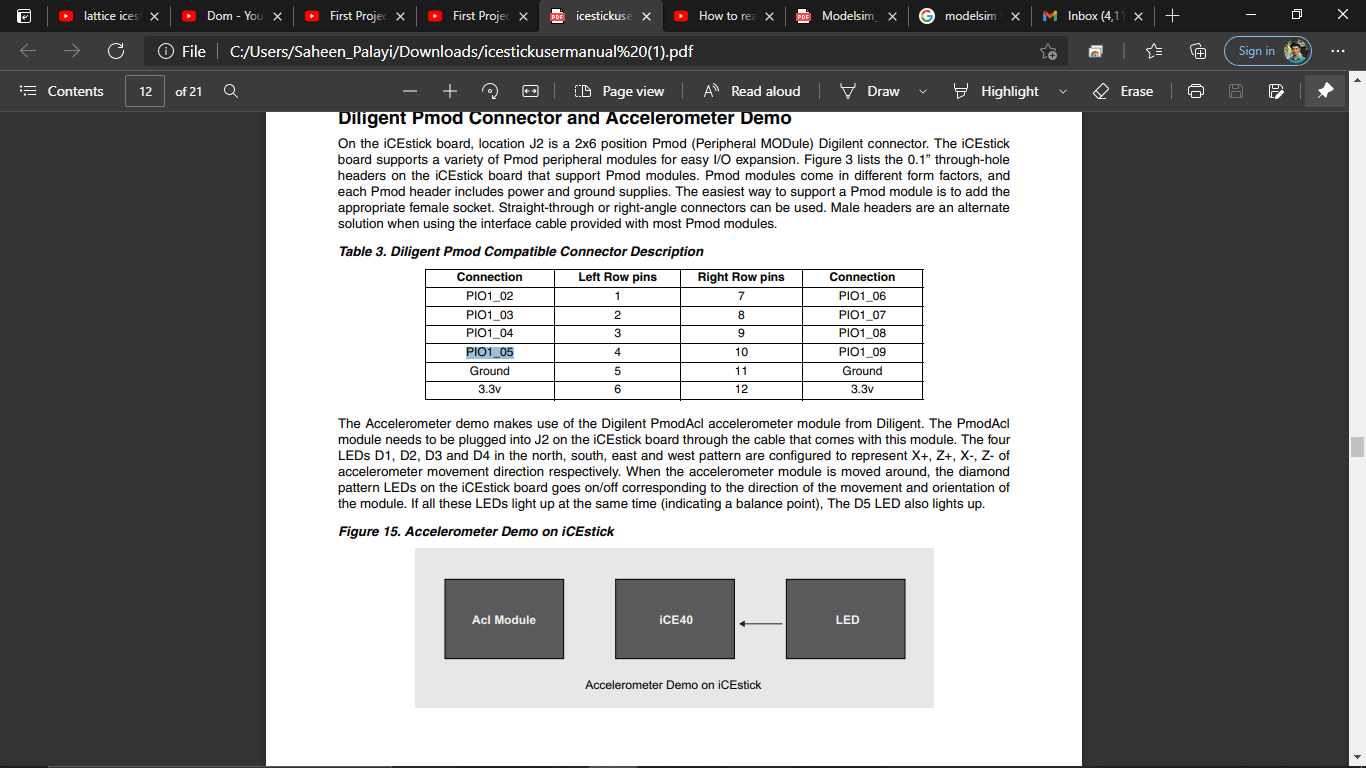
I selected the 4th pin of Pmode connector which is right above the GND pin But it desnot provided the PIN number I refereed the circuit diagram of Lattice ICEStick to get the pin Number.given on the same document
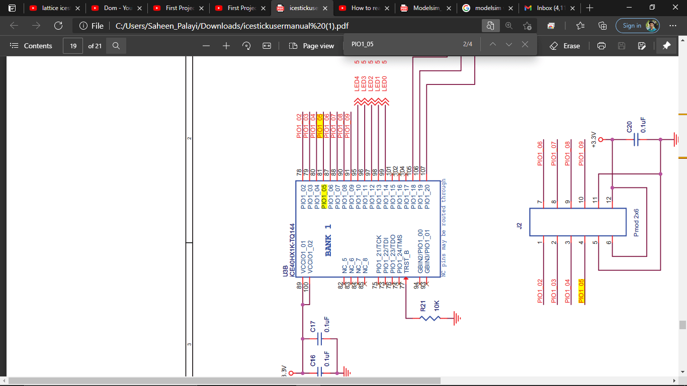
so The PIN Number for the button is '81'. Then I selected the Pin configure Icon on the ICECube2 tab to set the input Out put Pins
That opens a new window tab in the iCEcube2 to setup input,output pins
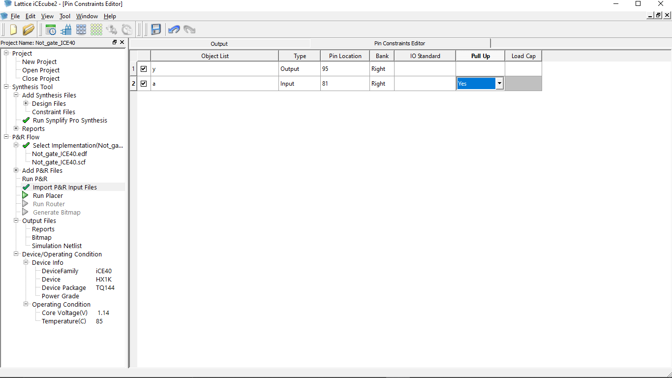
I entered both the input and output PIN numbers and also made Pull-up enabled for the INPUT PIN because i'm connecting button without any pull up resistor . some pin of this Board supports the Pull-up features
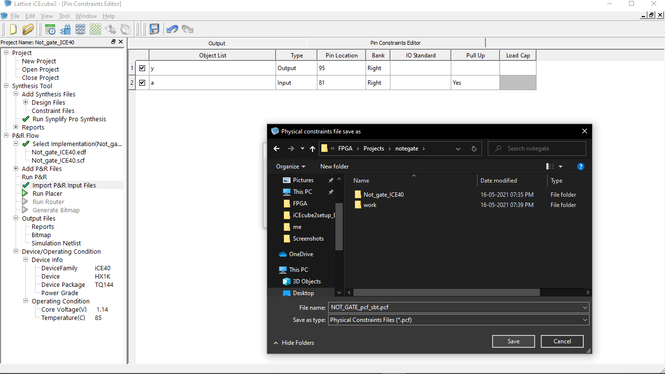
We can also save the pin configuration setup as a file for future modification.So,by clicking Save icon on the top I saved to the project directory along with the Not-gate.v code
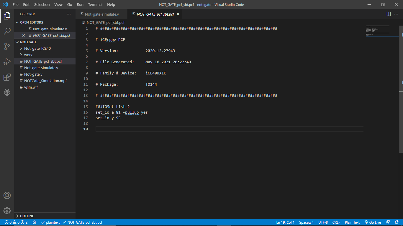
PIN configuration file saved with '.pcf. file name extension that we can open in code for future editing and other modifications
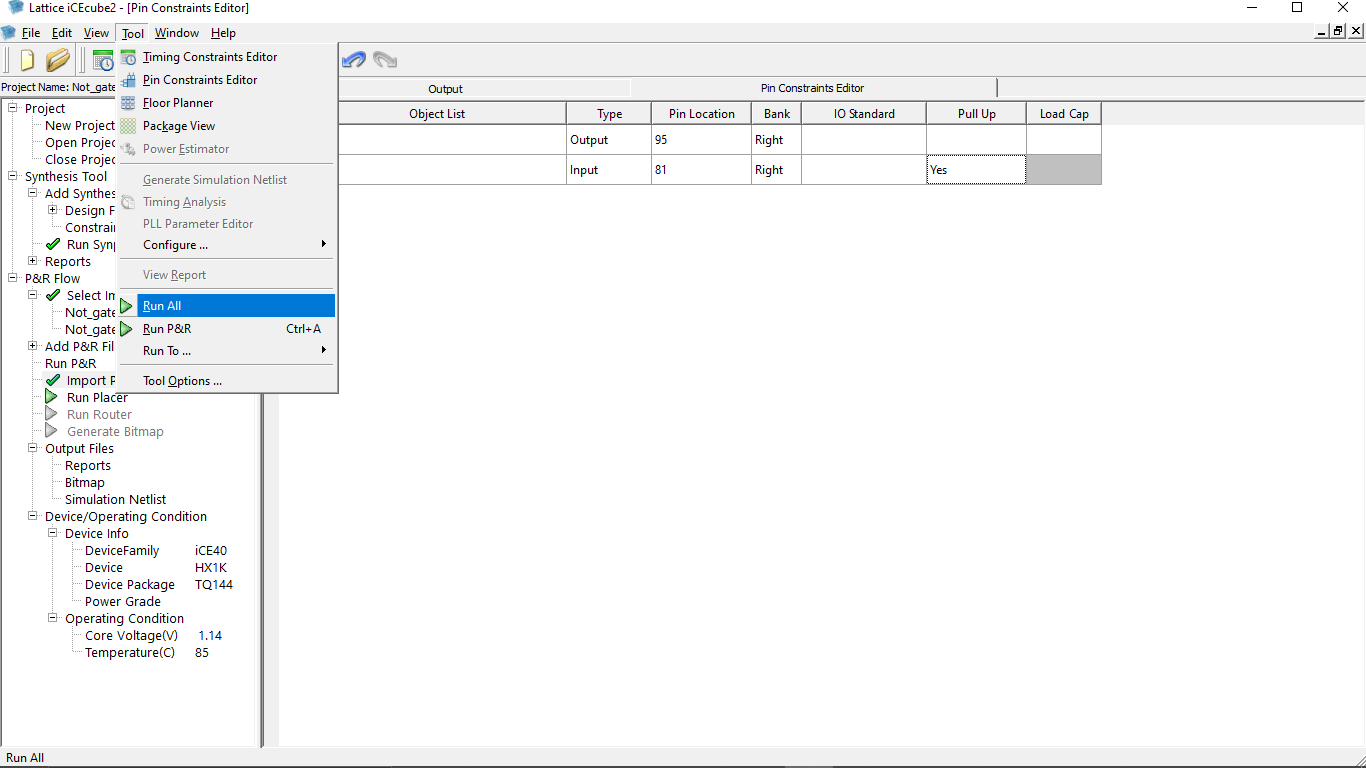
Then I Generated the bin file in the ICECube2 by clicking 'Tool >> Run All' option that generated the BIN file for programing to the ICEStick inside the project directory the Job of the iCEcube2 is finished here
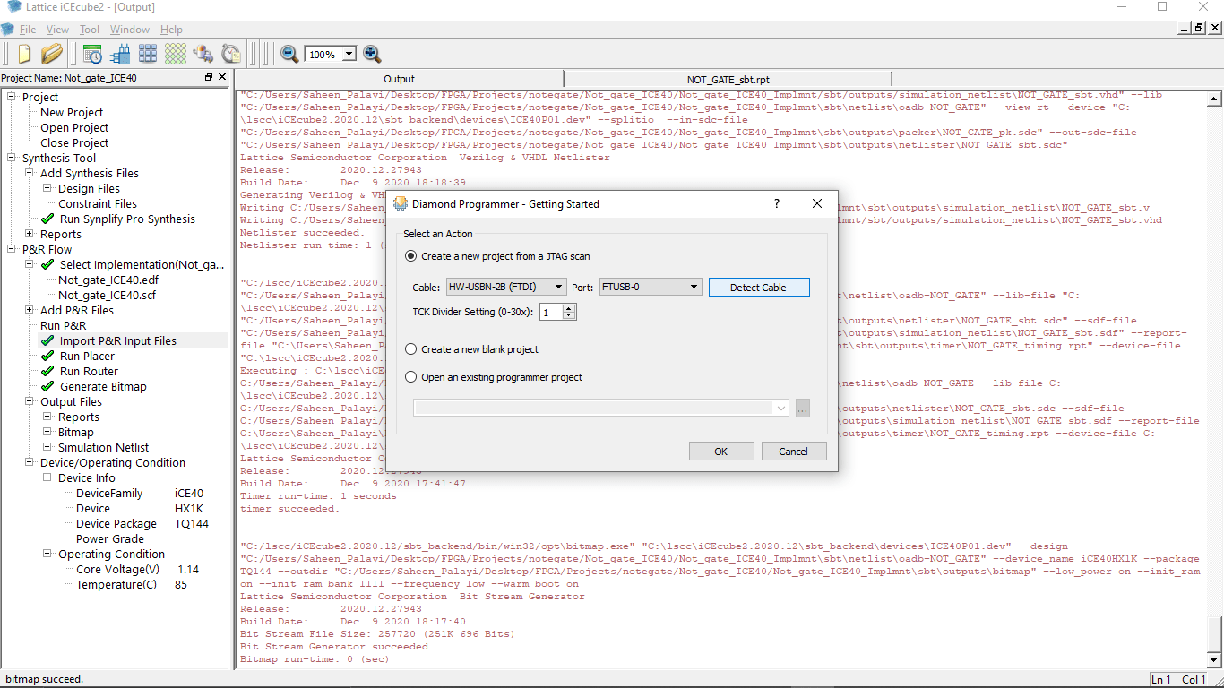
I Plugged the ICEStick Evaluation Board to my Pc's USB port and opened the Diamond Programer tool.Then I clicked detect Cable it will detect the ICEStick as an USB FTDI Device.after I Clicked 'OK' button to continue
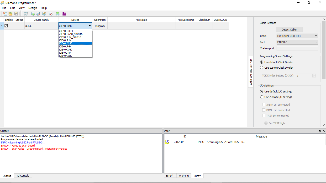
After that I started to setup the device By selecting...
- Device Family --> iCE40
- Device--> iCE40HX1K
Then I clicked 'program' under Operation
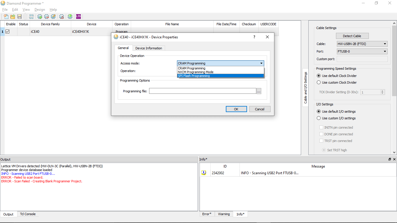
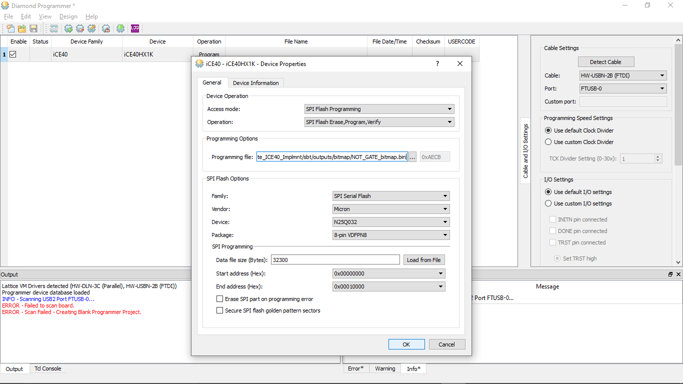
In the Opened window I changed the Access Mode: to SPI Flash Programing.Then I started to change the rest of the information
- Vendor --> Micron
- Device --> N25Q32
- Package --> 8-pin VDFPN8
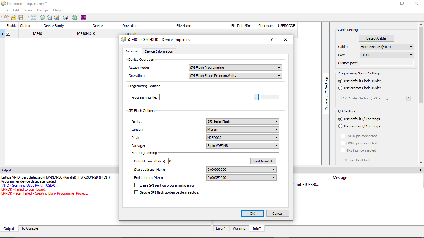
After selecting all options I loaded the BIN file generated by the iCEcube2
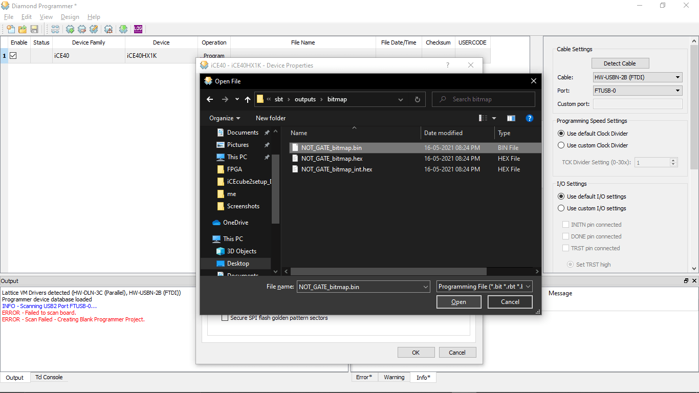
The file located in the Project Directory saved by the iCEcube2 which is Not_gate_ICE40 >> Not_gate_ICE40_Implmnt >> sbt >> outputs >> bitmap >> NOT_GATE_bitmap.bin file
After selecting the setup is finishes then I clicked the Down Green arrow Icon above to download the program to the ICEStick Board
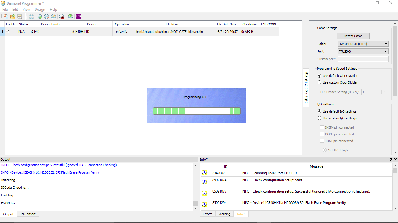
The Programing started it Red the chip then will Erase,Flash,Then verify
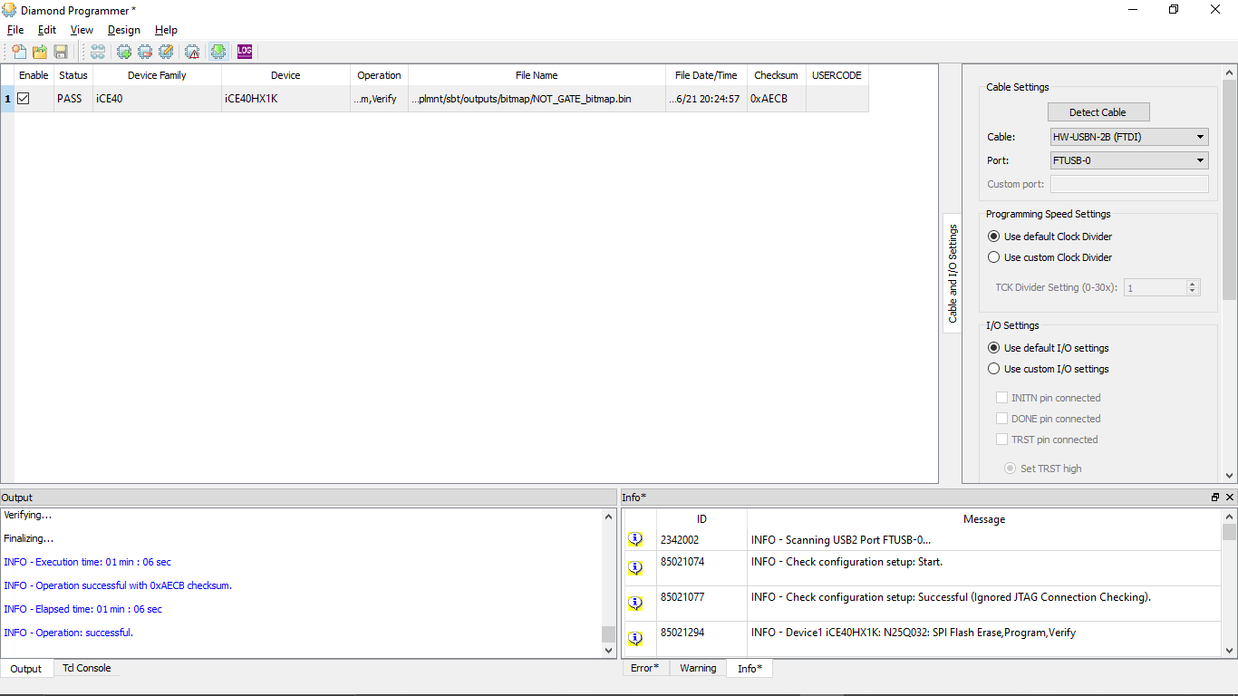
Done! I got Success message .(I also got error on first try but changing the USB PORT of My PC worked! without any error.Refer this )
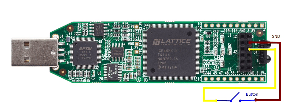
I prepared a push button on a bread board and wired like in the above figure.See the video below to for the results!
Servo Sweep Experiment
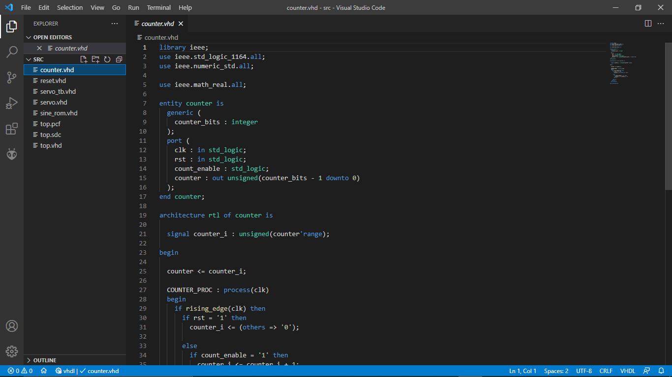
I found a Servo sweep program which was done in a FPGA from vhdlwhiz.com.It was written in vhdl Language I wasn't familiar with VHDL.so I gave it a try
Simulation using Mentor ModelSim
Lattice Also providing it's own version of Simulation software Called Mentor ModelSim.So I tried out the software for simulating the Not gate.We get Digital wave OUT PUT as simulation results
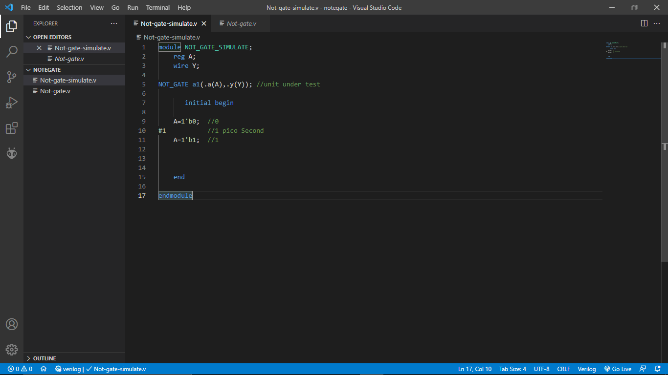
In order to simulate I created another program in vs code with a different file in the same directory
        module NOT_GATE_SIMULATE;
            reg A;
            wire Y;

        module NOT_GATE a1(.a(A),.y(Y)); // calling the NOT_GATE program here

            initial Begin-NOT

          A=1'b0; // Input set to 0
        #1        //1 pico Second time delay
          A=1'b1  //Input set to 1


            end

        endmodule
so the above code is made for the simulation only not for programing the FPGA. I made diffrent module called 'NOT_GATE_SIMULATE' then I added an input 'reg A' then wired output to 'wire Y' next I called the 'NOT_GATE' module I build in the previous program in to this program and passed the input and output variables
Then I opened the Mentor ModelSim Lattice FPGA edition software .which already installed along with iCEcube2
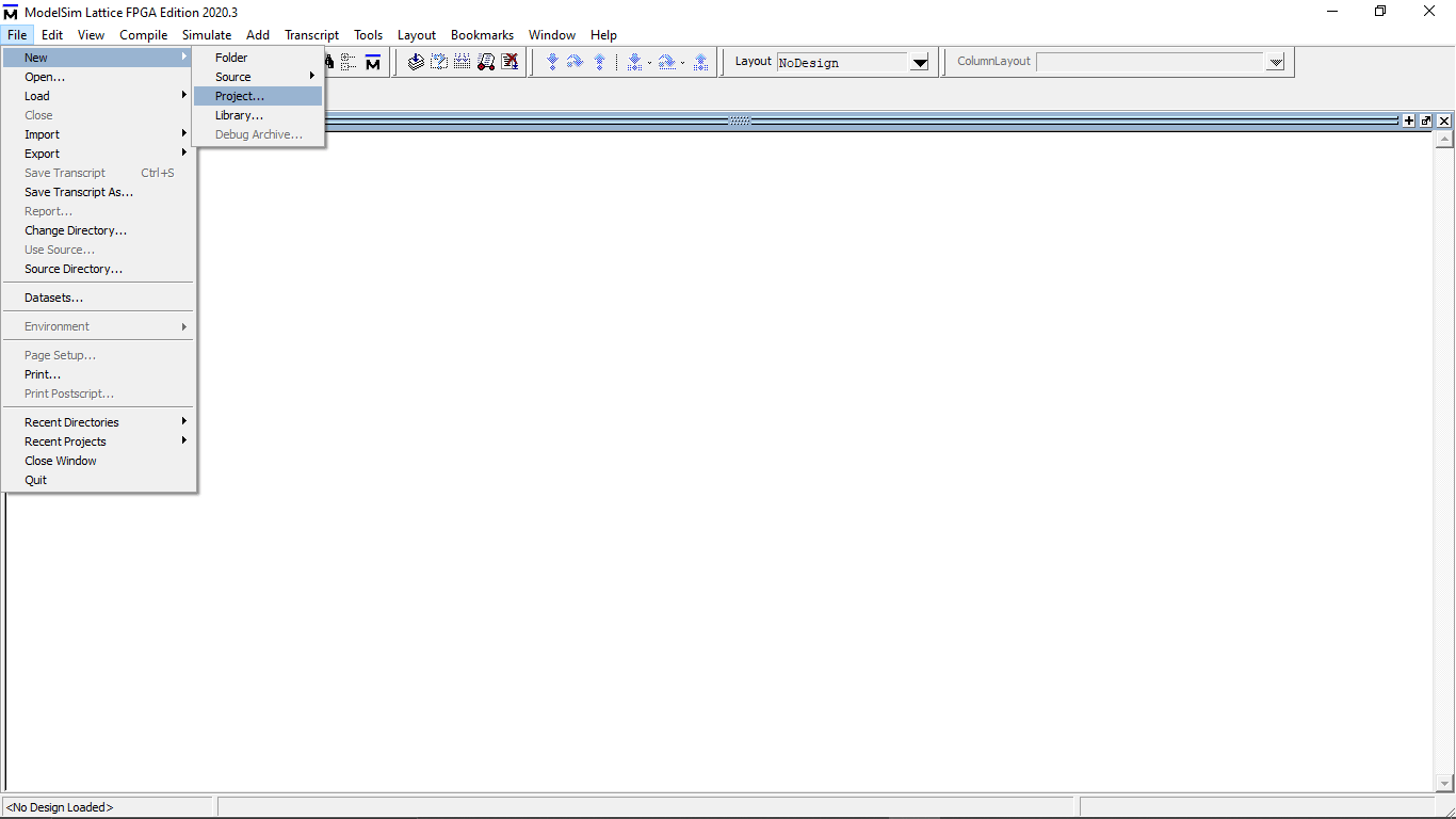
Then I opened a new project by clicking File >> New >> Project
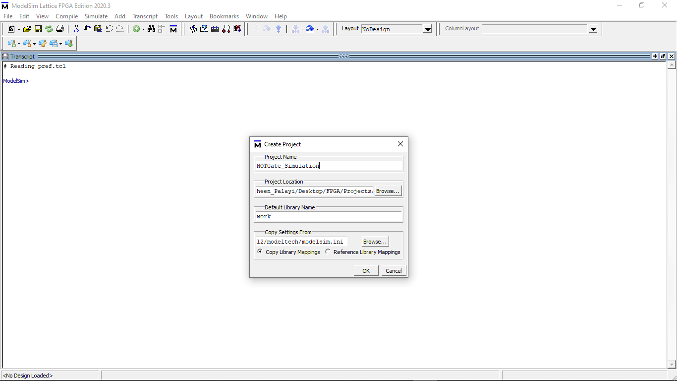
I given a name to the project and stored into same directory which I created for the Not gate Project
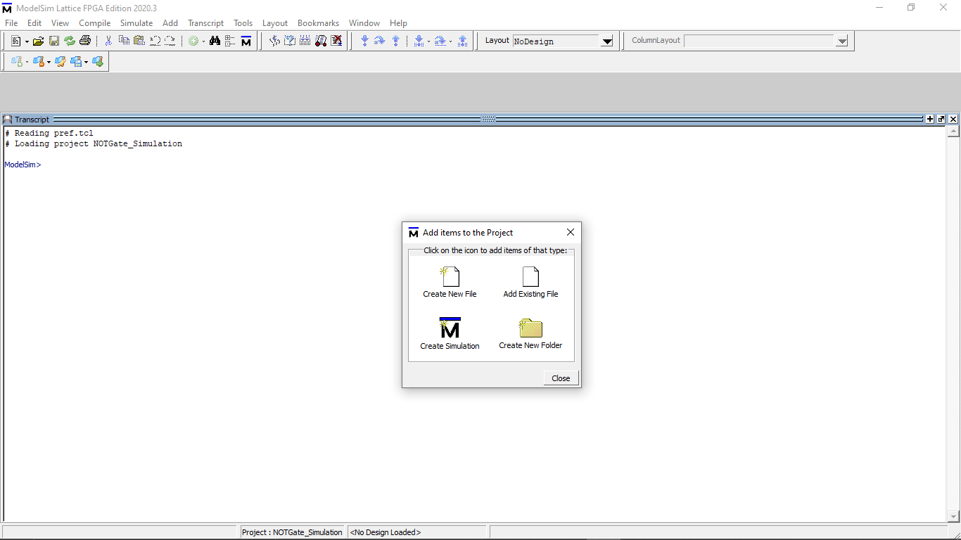
After clicking OK now I have to provide the files so, I clicked on "Add existing File" button because I already the program
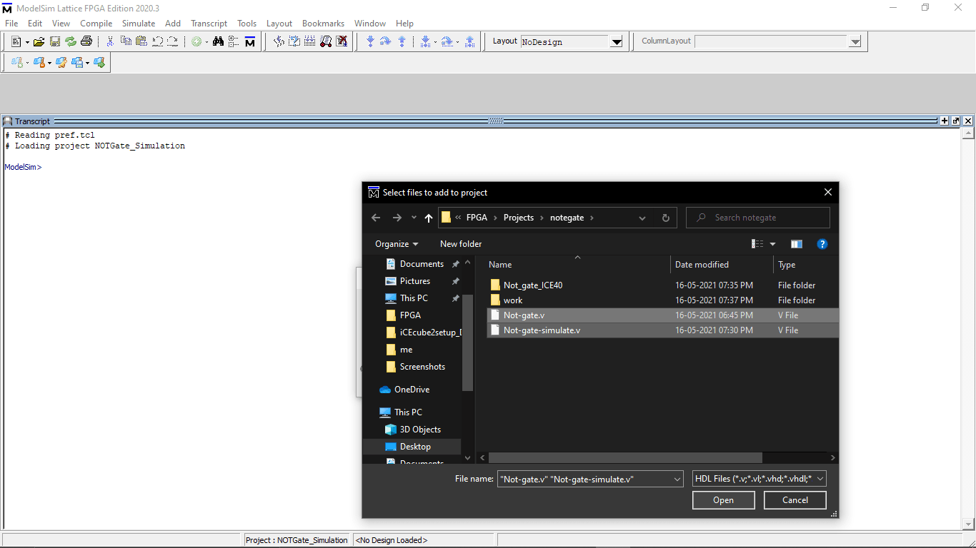
Then I selected browsed and selected both file and opened to this ModelSim software
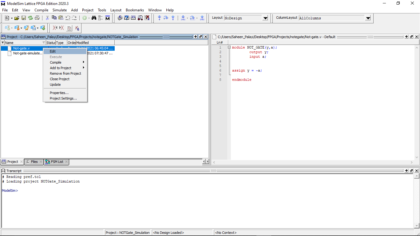
You can see both files available on tab.Unlike ICECube2 software ModelSim supports It's own Editor to write code and save them .by right clicking the mouse on the file will allows to get the text editor to edit file
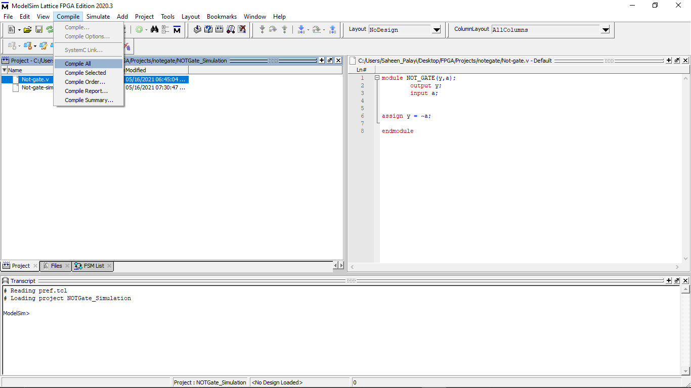
Then I compiled the files by clicking Compile >> Compile all option from the above tab
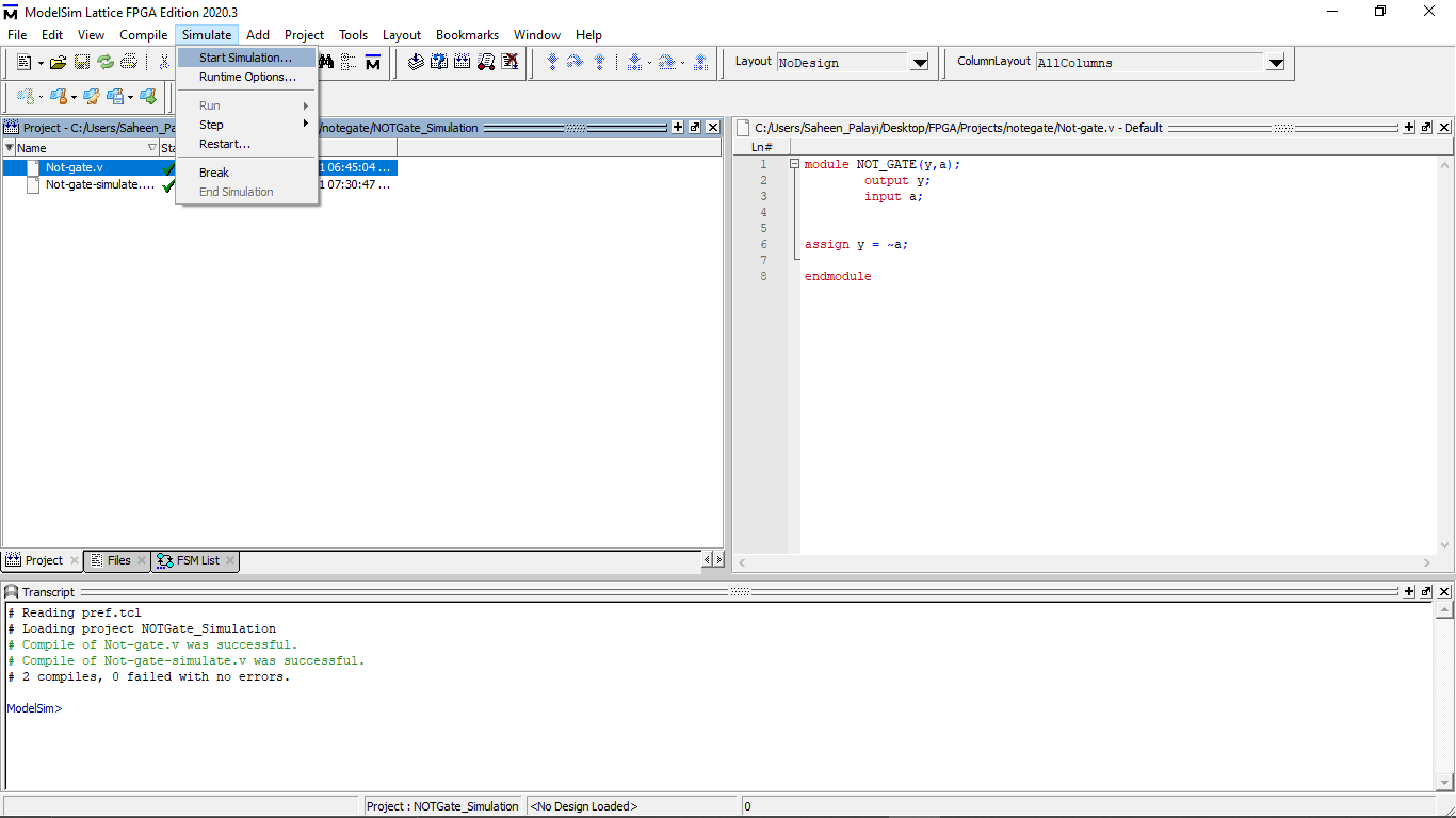
Compilation was successful and got verified tik marks for the files .After that I clicked on Simulate >> Start simulation option for starting the simulation
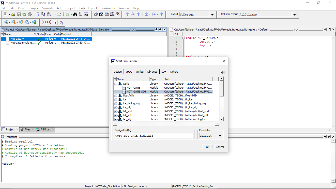
In the Opened window I selected the Simulation code file only which is shown under the work directory
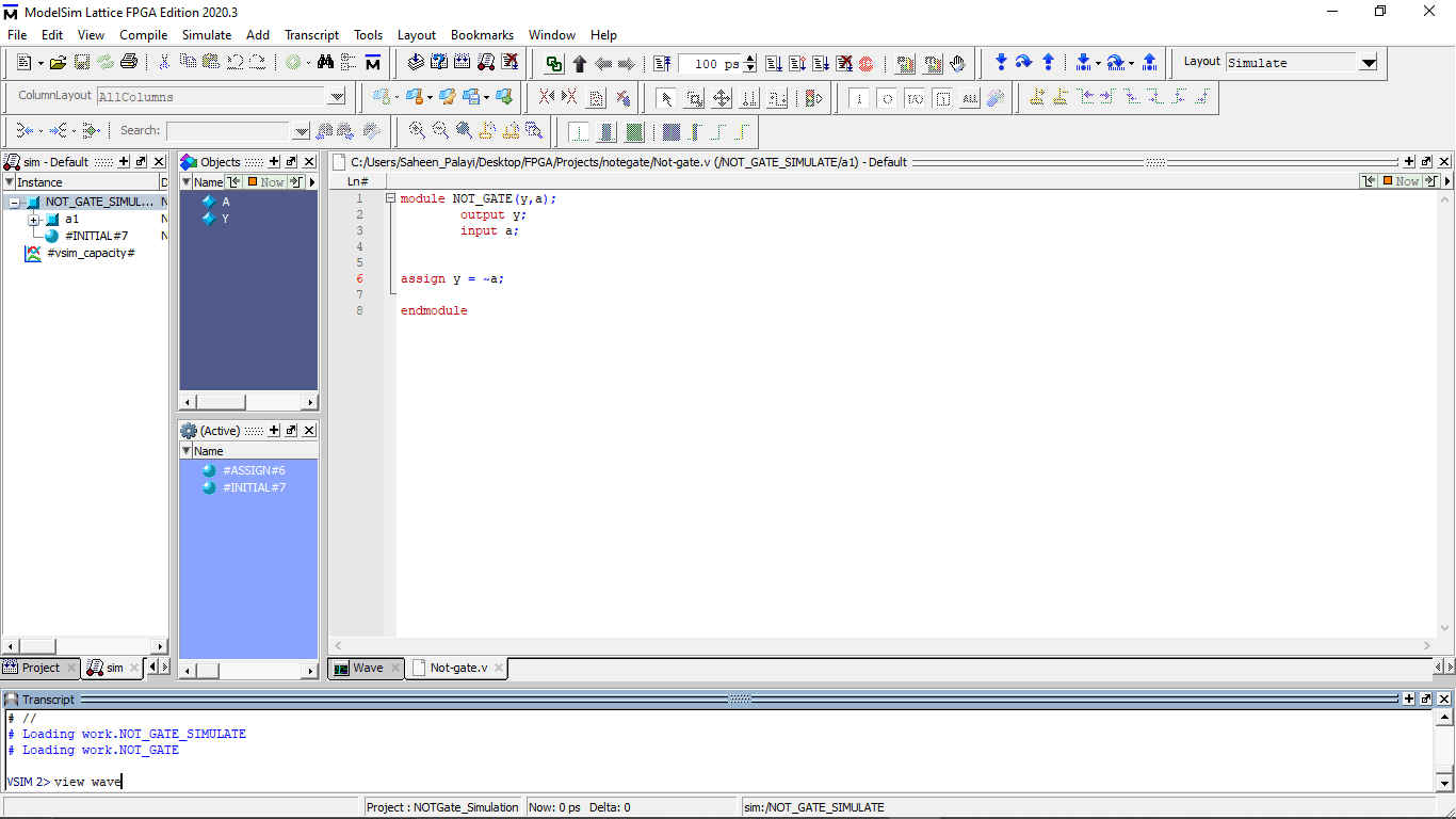
Then I used the terminal command for opening the wave out put window
view wave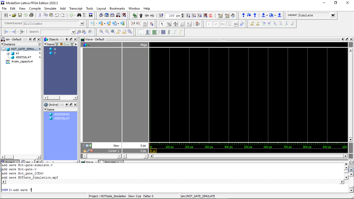
The wave window opened.By typing the add wave command load the wave file from the compiled directory
add wave *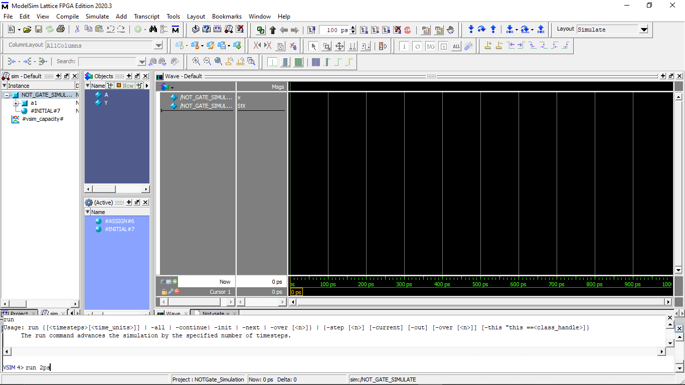
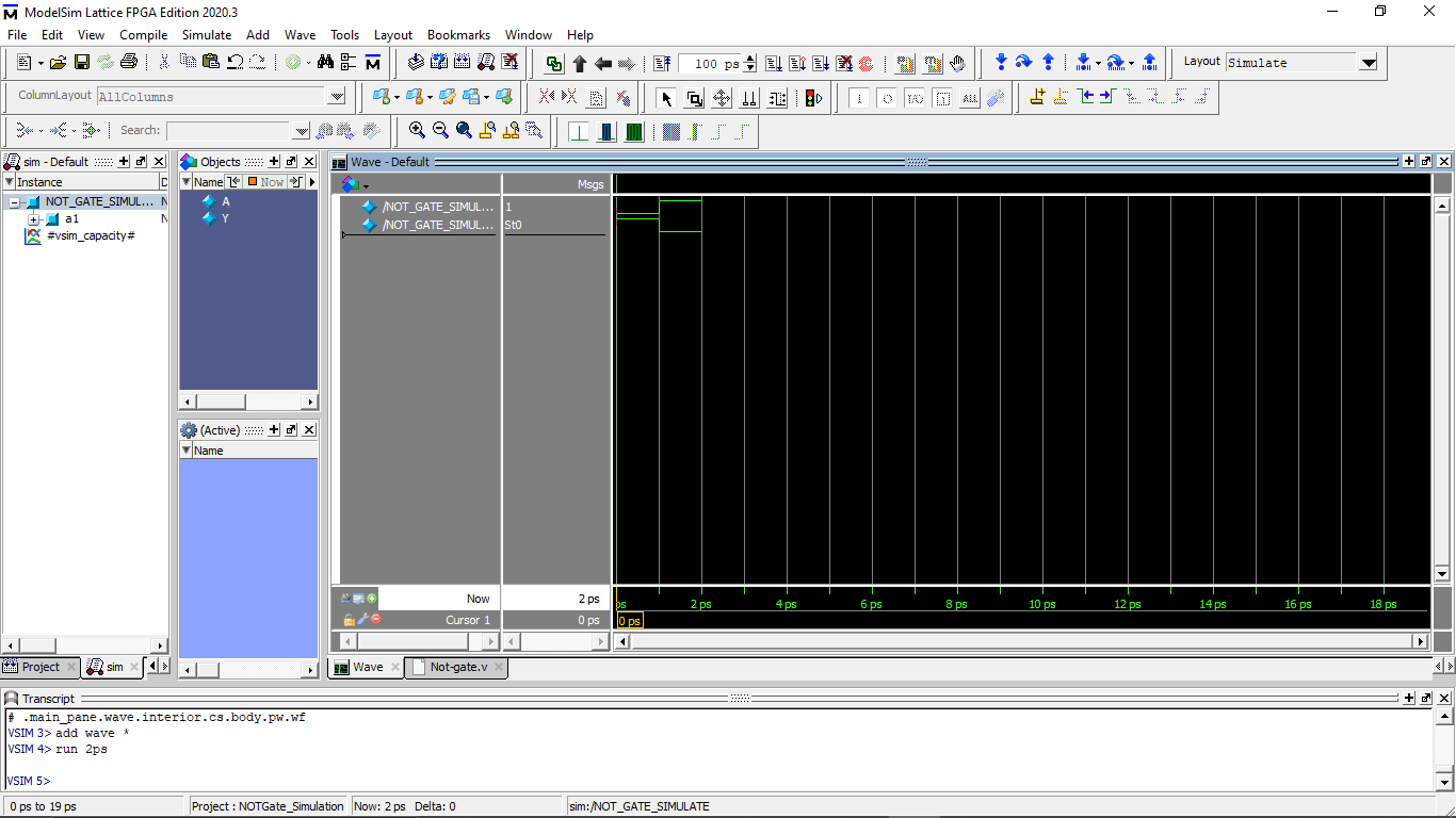
Then Runs the simulation for 2 Picosecond by timing run 2ps code in the command line.I programed each signal delay for 1 picosecond .so I have two inputs 1 and 0 total for 2 picosecond
run 2ps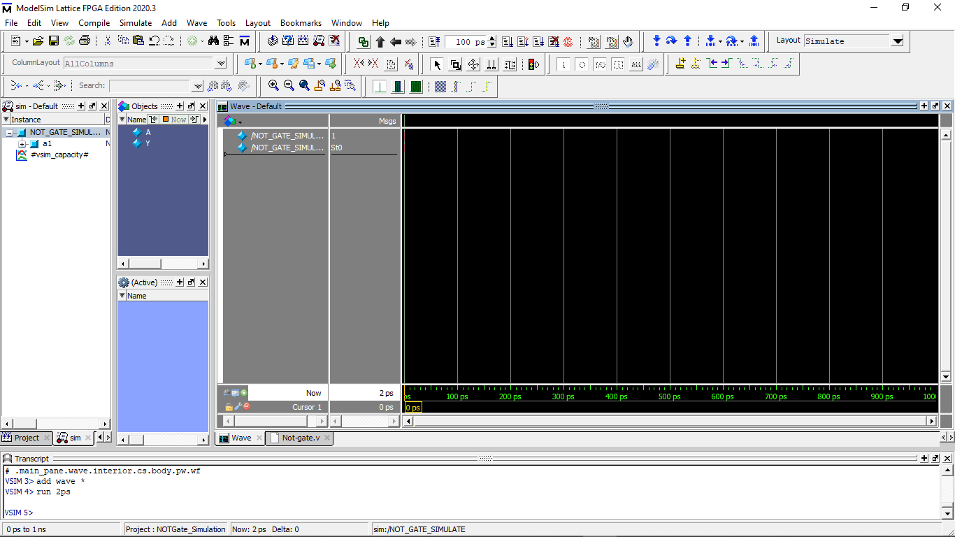
we can see on the figure that the wave window got something on the screen I have to zoom to see that because it was only for 2 picosecond
This is the wave form Expected for the NOT Gate program and also I got the same results in the simulation
we can also wrote the both code in the same file which also works .this type experiments are the one that I learned during my Diploma.we were using a different software. but I didn't find interesting to do this kind of simulation.but it necessary to study the OUTPUTS
Icestudio the Open Visual editor for FPGA
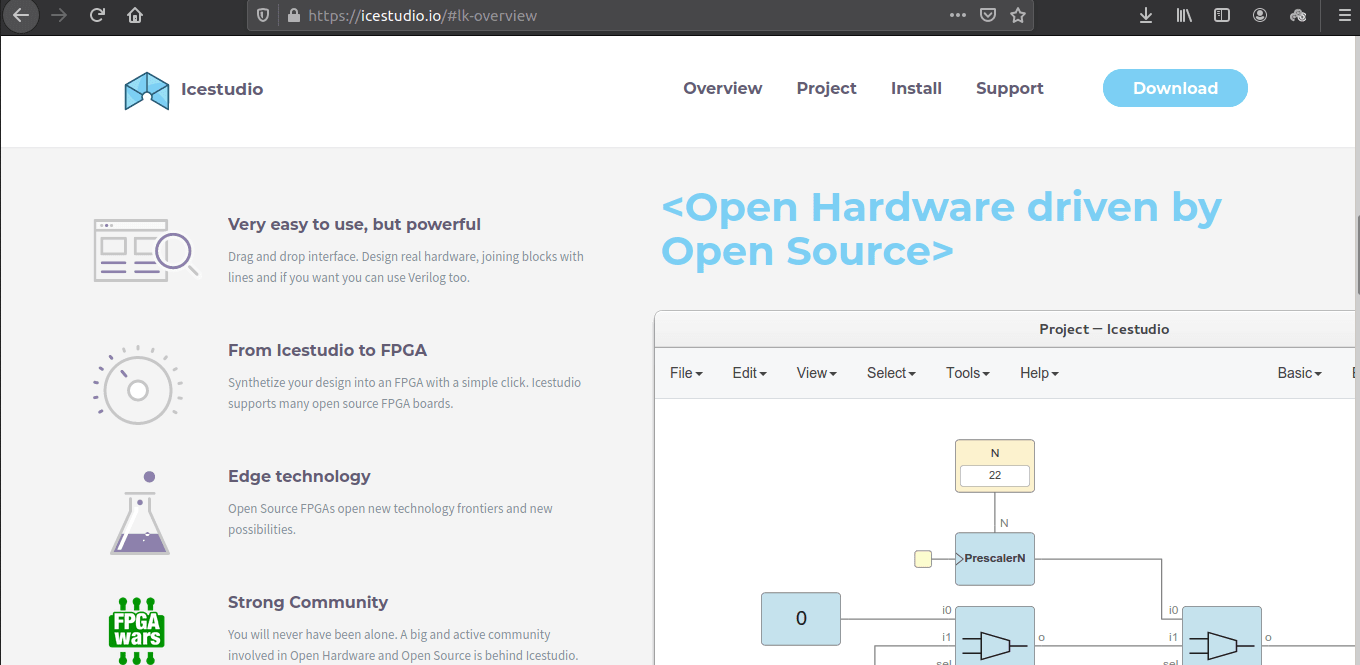
Icestudio is a revolutionary Open Visual Editor software builds for open FPGA boards.Which is completely open source like arduino and available to download for all the platforms
The Components like Logic gates,counters...etc.. are available in the Icestudio,That we can just drag and drop and can br connect just using mouse also each blocks editable as in Verilog language
I downloaded the Icestudio for windows from the icestudio.io and installed in my PC.It's supports all the open source FPGA hardwares like Tiny FPGA boards ,Lattice ICEStick and etc...
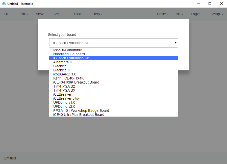
After Installation complete software asks which board that I'm using.The ICEStick Evaluation Kit also listed along with all supported Open FPGA boards
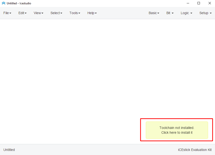
Then It shows notification banner says Toolchain not installed.so by clicking the banner it started to install the tool chain from the internetS
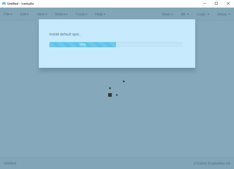
It takes some time.All features in this software is very simple with super optimized UI
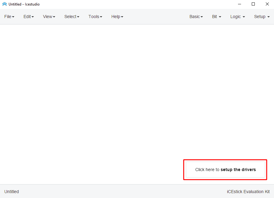
Then it says to setup the driver for the board.by clicking on that also shows a mini 4 step guide to navigate the driver installation process
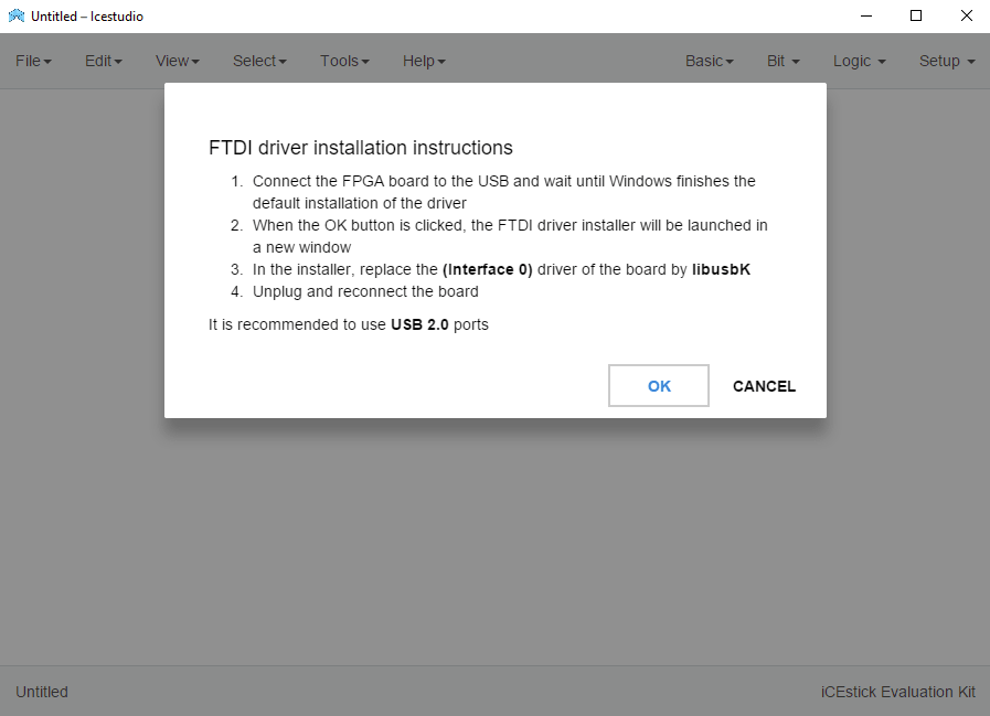
So I plugged the lattice ICEStick Evaluation Board to my pc and clicked 'OK' to continue
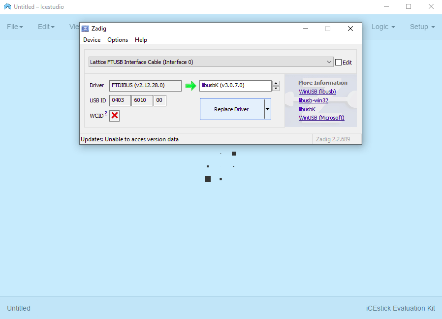
It detected the Board and recommended a new version of the driver automatically.I already have A driver in PC because I installed the lattice Diamond Programer first to try out
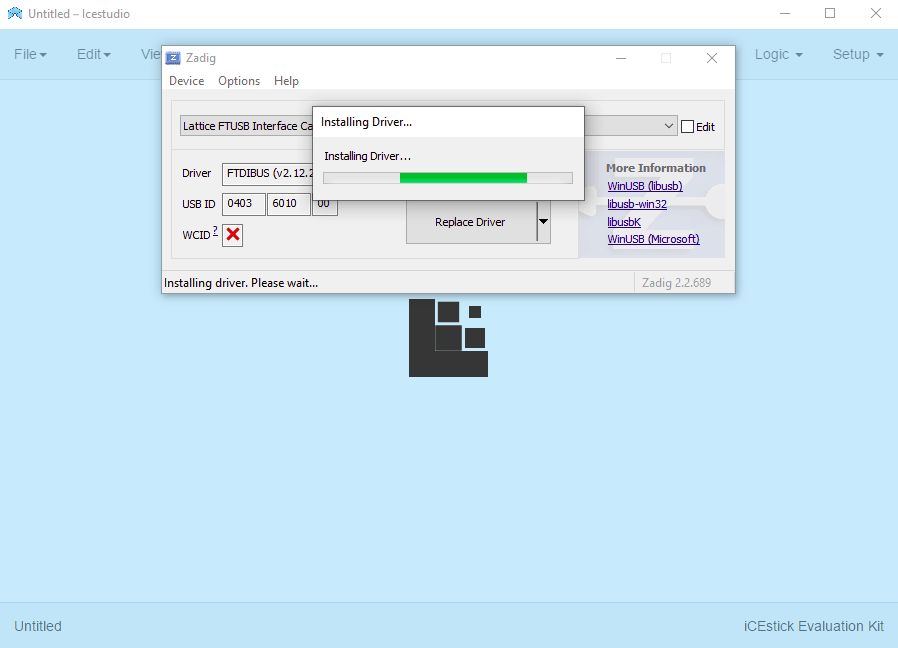
closed the tab after driver installation then unplugged and re-plugged the ICEStick board as per the Instructions
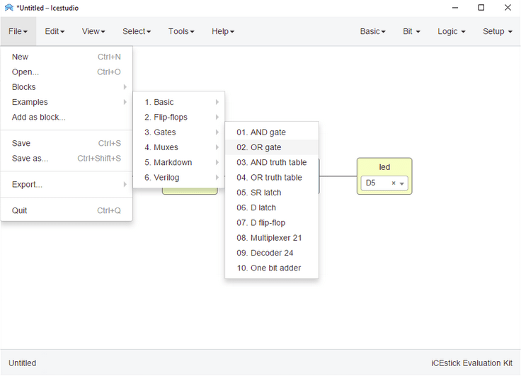
SO examples provided by Icestudio by default to Explore.The whole menu options are just like the arduino IDE
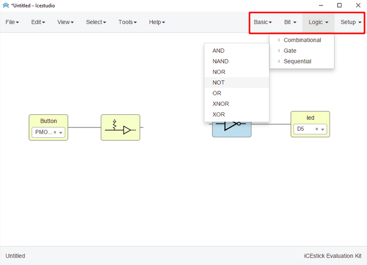
on right top options we can get some blocks which includes inputs,outputs,Logic gates,Flipflops and etc.. to make our own designs
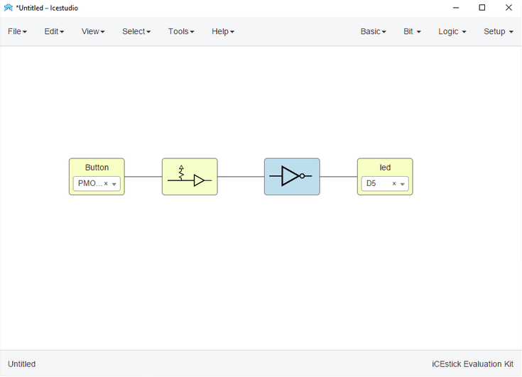
This the NOT gate project in Icestudio which I created similar to the previous ICECube2 NOT gate Project.It is very simple to do project on Icestudio only thing is we have to wire from output to inputs
Each block on the pictures are very relatable. first one is an Input block for the button and next one is the pull-up enable block.Then a NOT gate block and Finally a output block fo the LED.All the pin configuration are just dropdown-select methods.all are named by default According to the board
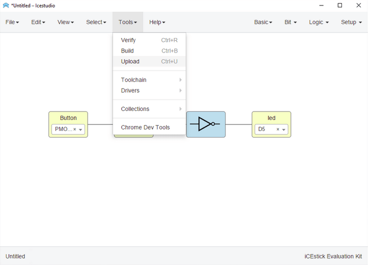
Like I said all the options are just like the arduino IDE very simple to verify and upload the programs
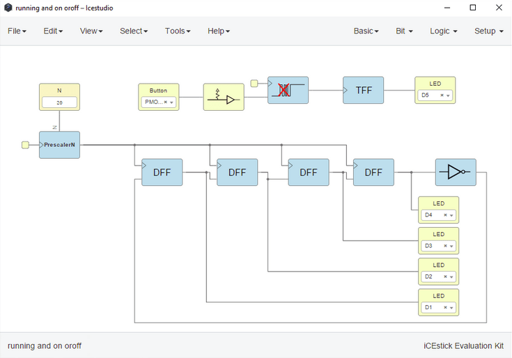
I mentioned that unlike the microcontrollers FPGA can do Multitasking at the same time.So,I did this running LED and a button toggle program for experimentation
on the video you can see I'm toggling the green led using a button at the same time the RED LEDs are running with out any delay or problems
PONG Game
Through exploring all of the FPGA development work flow My Intention was to make a simple display drive to drive a VGA Monitor using the lattice ICEStick Evaluation board
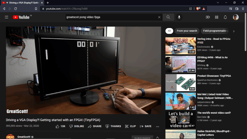
While searching internet I saw this video on YouTube from Channel name GreatScott. The german guy actually explained how to use and get started with a tiny FPGA development board try to drive an VGA Display just like I wanted. He pulled an Project named PONG Game some guy did on github and it's awesome The ice studio files also available.
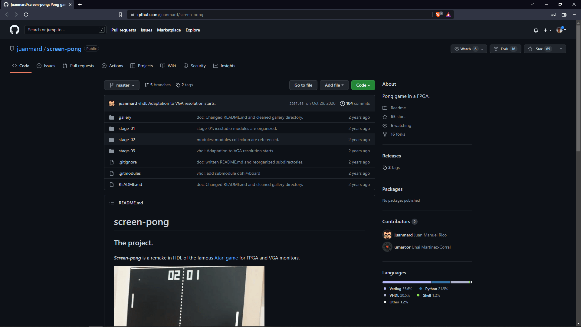
The github project named screen-pong is made by a guy called Juan Manuel Rico.It's a remake in HDL of the famous Atari game's Pong game fro the FPGA and VGA Monitors. I downloaded the entire repo which is included all the game source files and few examples of running VGA monitor outputs in FPGA
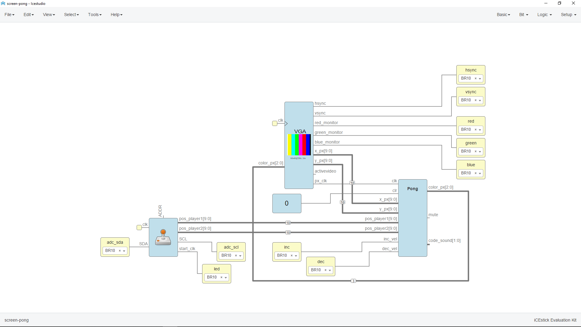
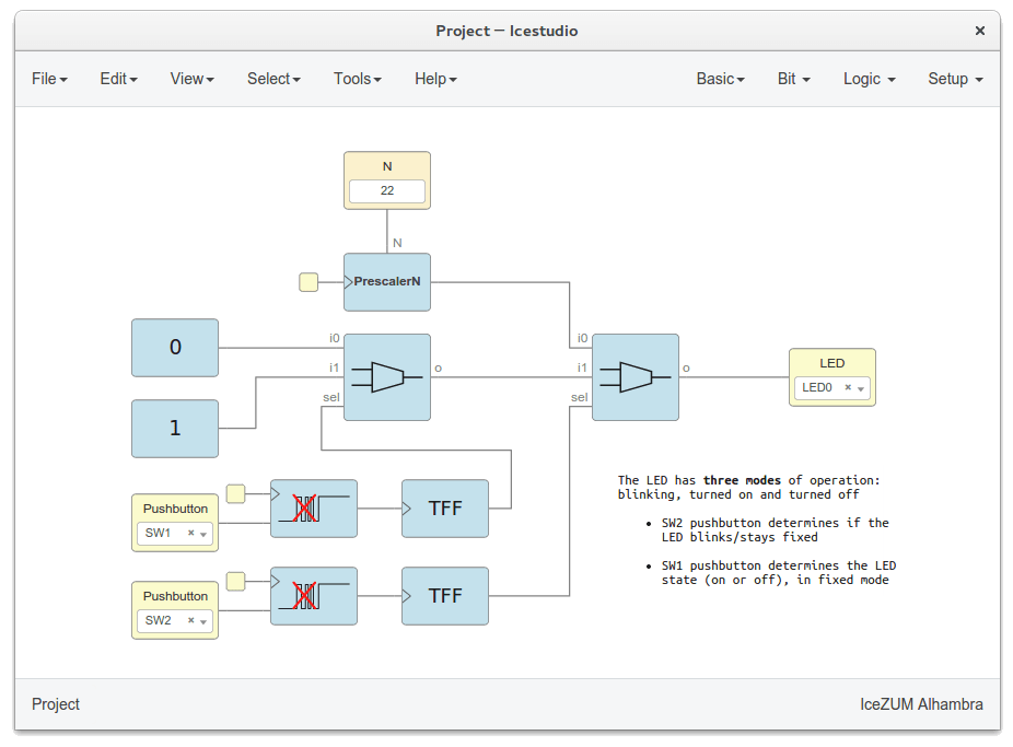
I opened the Stage 1 Pong game project Icestudio which is specially built for iceZum Alhambra FPGA development board as per his github documentation. And this is also works in the ICEStick Evaluation board because both uses same FPGA chip.But there is another problem to implement this Program because it need a joystick controller with I2C interface which is I don't have.
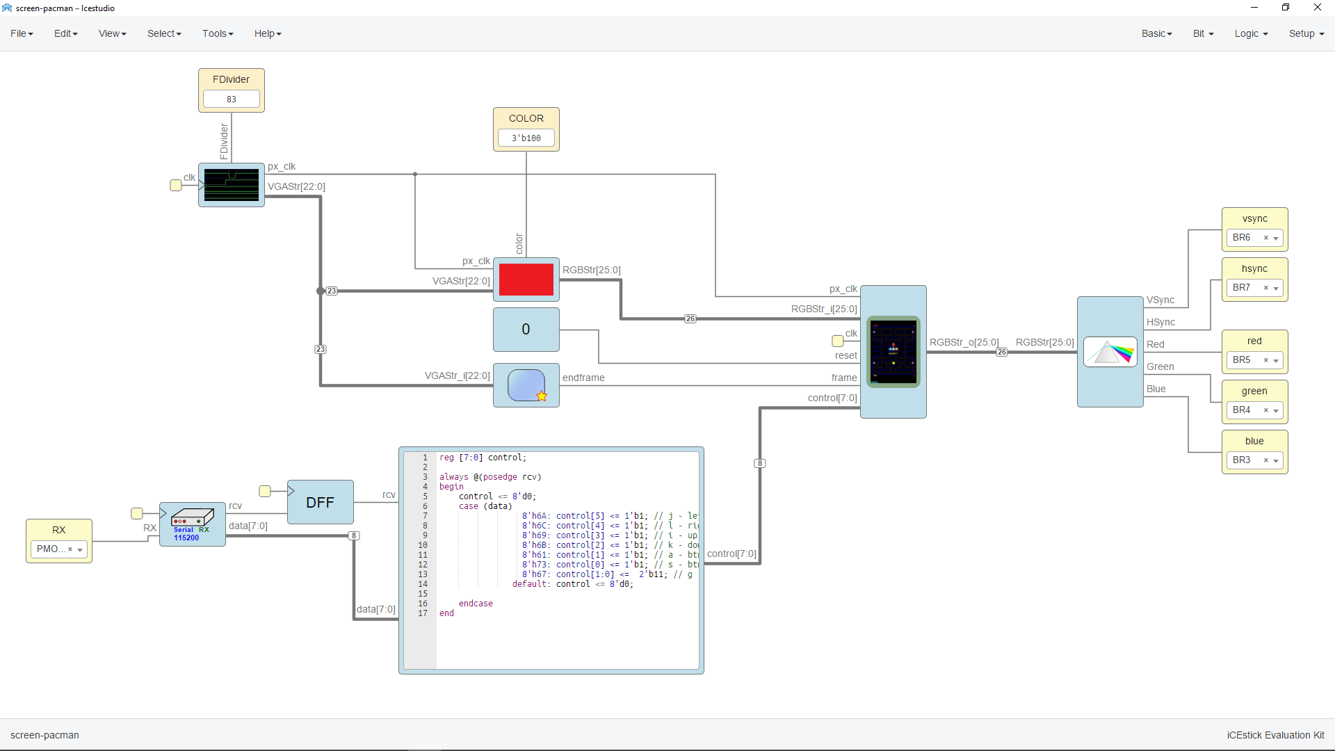
By doing dome more digging on the internet I found a Pacman game github Repo which is also made by the same guy,Juan Manuel Rico. so I downloaded and opened in the Icestudio and converted to a icestick project, Then assigned the PIN Numbers for the VGA output.
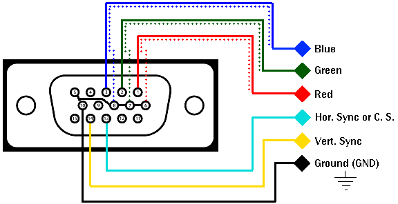
- PIN Diagram
- VSync -- > BR6
- HSync -- > BR7
- Red -- > BR5
- Green -- > BR4
- Blue -- > BR3
- GND -- > GND
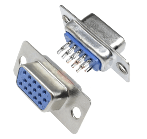
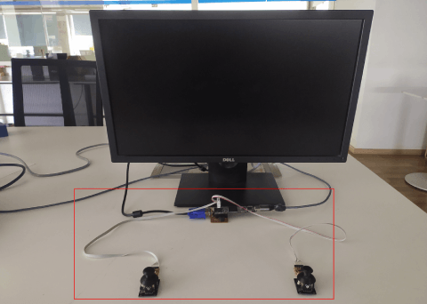
Here is the VGA connector I've got from my home and It's 15 PIN straight connector used for VGA extender cable making. Then I connected to a computer monitor which supports VGA source using some jumper wires,breadboard and the VGA Female Connector.
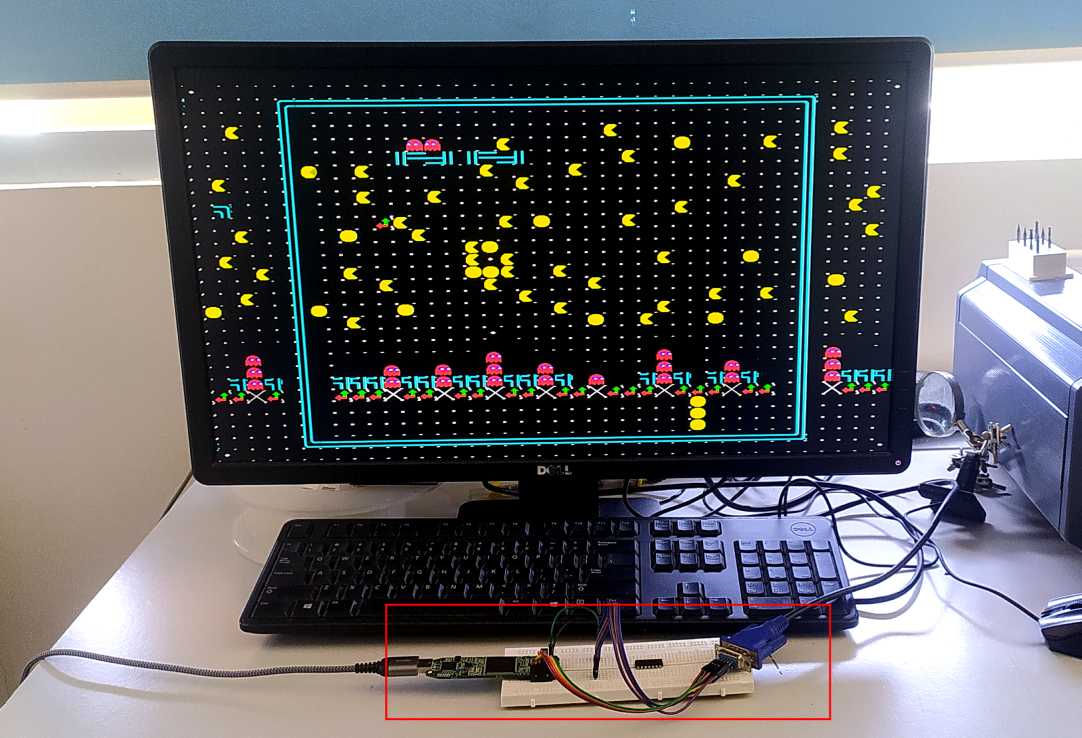
Tadaa... I got the VGA out from the lattice icestick FPGA and it's Pacman game console now .But I've no idea how to play a Pacman game.
Designing the VGA Hardware
For making the connections are perment and easy to use I've designed the PCB hardware for the Icestick evaluation Board . We don't have the FPGA chip in our and also required micro soldering skills to build circuit with the chip.
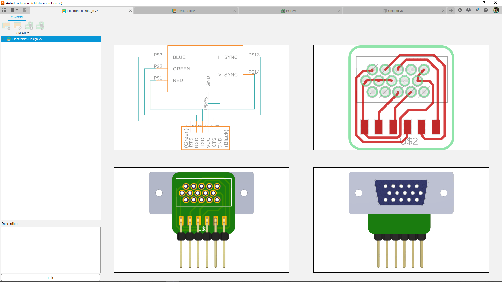
Here is a small fusion 360 PCB made for the Connector for making it 90 degree bend and solder able to the final PCB .The best for the this project is the 15 PIN 90 degree bended PCB VGA connector but this is the only I've got so I decided to go with it
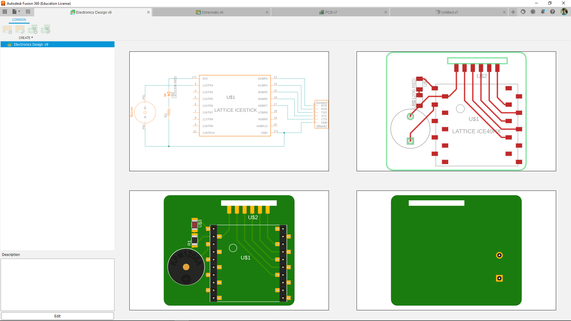
Then I designed the Shield fo the Icestick evaluation board with 10 pin female pin headers and also added a power LED ans a Buzzer. U can see there is slot in the PCB to add the VGA connector PCB to the Board by soldering them together.
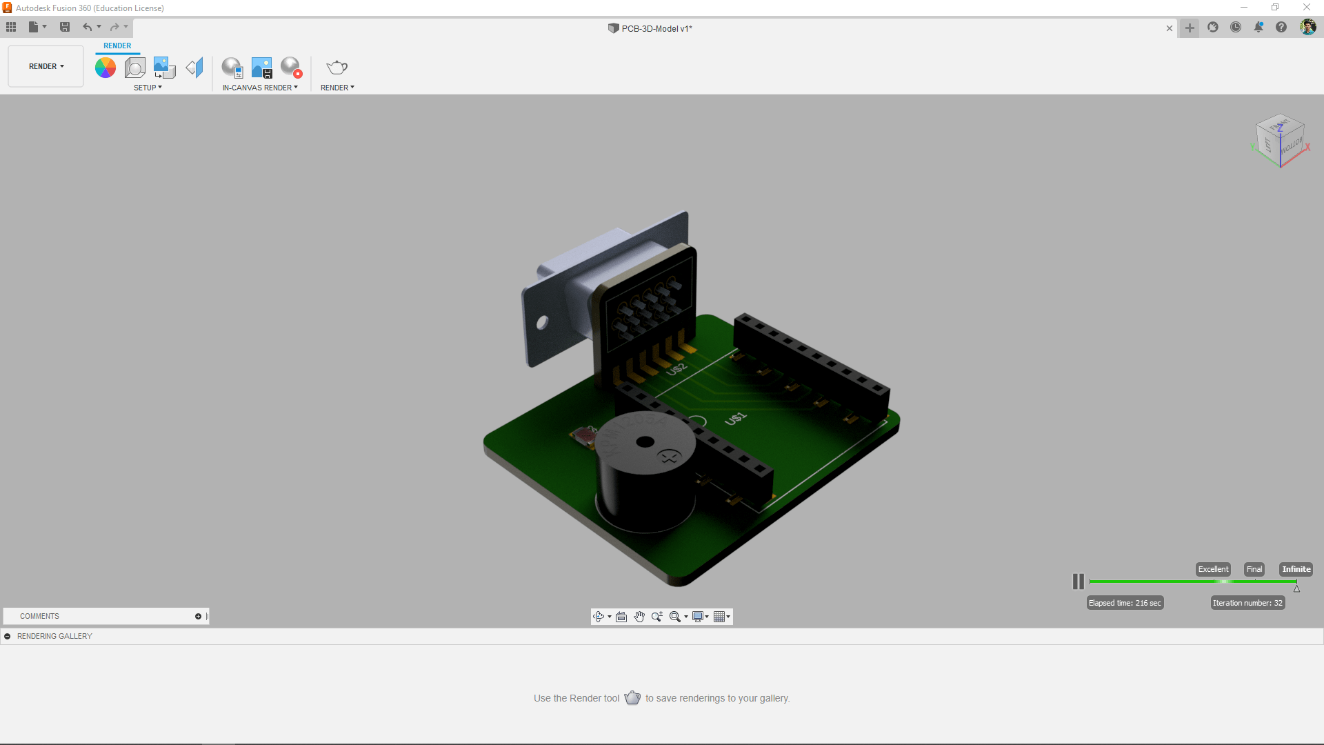
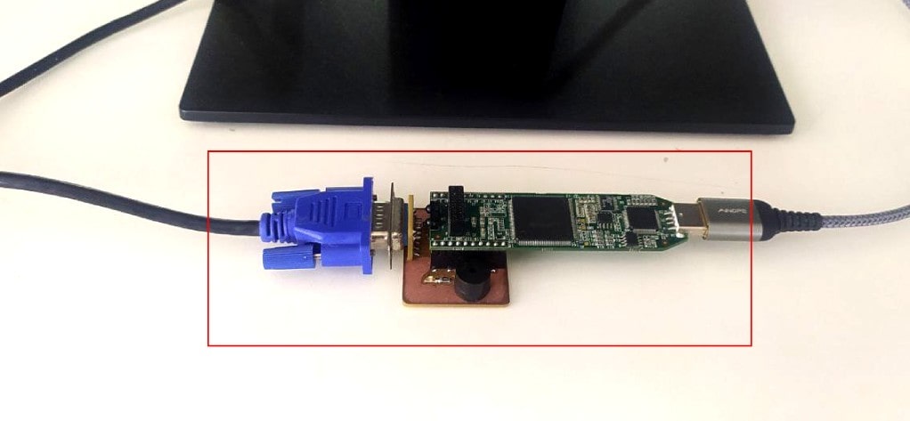
Here is the final Output of the Entire Hardware setup I'm making,This way I can plug everything in compact way. Awesome! right?!
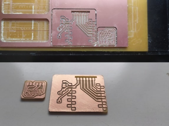
Then I milled out the PCBs in our Modalla milling machine and the Endmill of the machine wasn't that good and the cutting edge of the Endmill loses its quality by time. So required sanding after Milling.
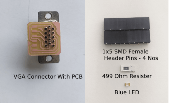
Then Gathered all the components to solder the PCB . And also a Buzzer is required to add in this picture but did not find in our inventory I have to get it from out side.
After I bought the buzzer I soldered to the board. But I had to use the Through hole rivet to solder the Buzzer because it's not SMD. See my Machine week for how to steps. Additionally this time I tinned the pads before riveting then I heated up after riveting the hole for making good contact between both revet and the PCB pad.
Here is the beautiful and satisfying part. I made the slot in the main PCB to insert the PCB which solder to the VGA connector It is one of the awesome technique used in some electronics controllers in the Power electronics I've seen this before
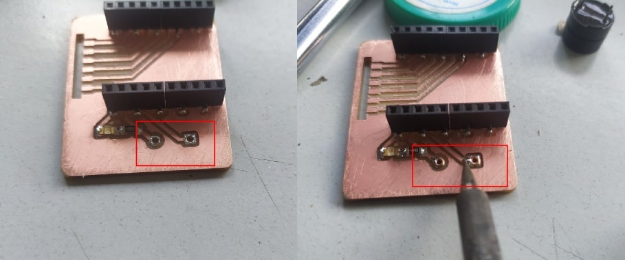
But while learning about the VGA signals from FPGA I noticed that the RGB signals needs to gos through a 270 ohm series resister according to This Documentation from fpga4fun.com. because the RGB signals are analog signals and the Vsync and Hsync signals are digital signals.
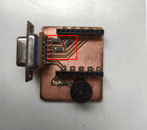
So I interrupted the RGB tracks with a knife and placed a near value resister from required as per the availability.
The Controller
For The user controller the Pong just need four buttons for each user and the Pacman required a serial communication device which send " j, k, l, i " for forward,backward and left,right controls @ 115200 Serial baud rate
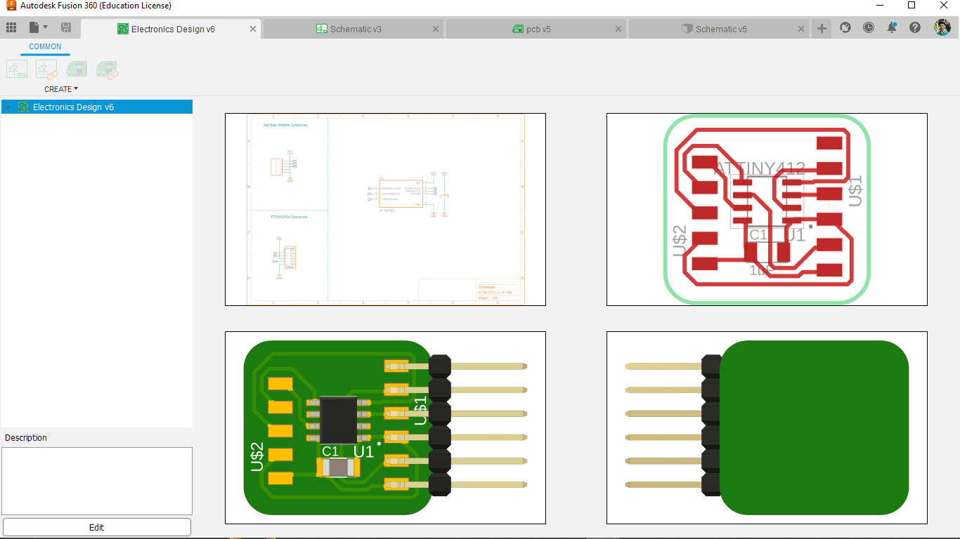
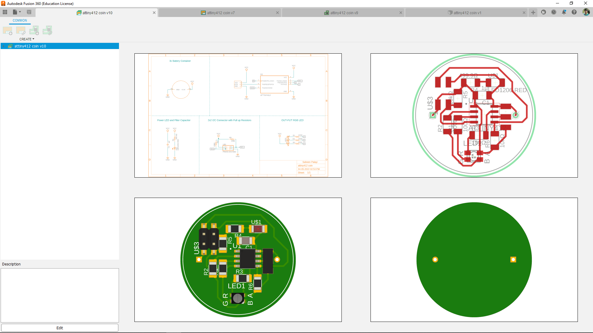
I've found some joystick module at the lab and designed a converter board using the Attiny412 in fusion 360. Because the joystick output is analog out put we cant read that directly using fpga so the attiny412 works like a ADC converter here also needs to make program to send digital signals according to the joystick movements.
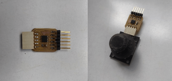
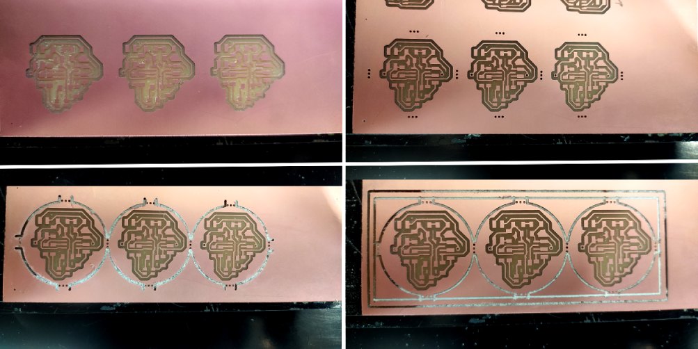
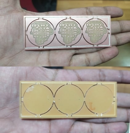
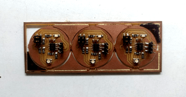
After Designing I milled out the board and soldered all the components which is only required a capacitor and two connectors alongside the Attiny412 AVR chip.
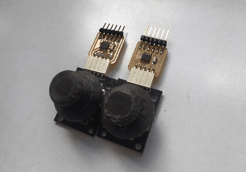
I replicated the process again for two player and those joystick caps where 3D printed by me that was missing at our lab.So the hardwares are ready now It's time to test the gaming console.
Programing the screen-pong Game
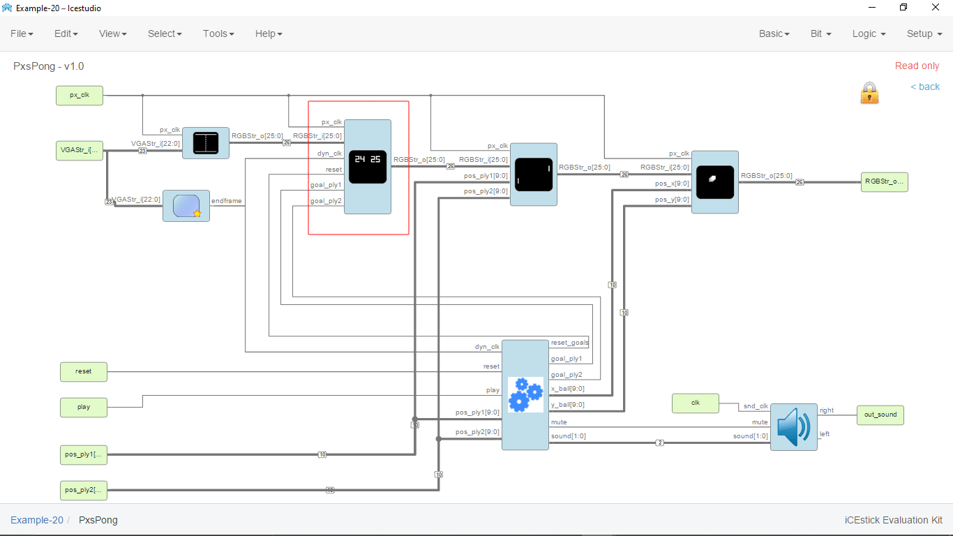
By doing some try on the screen-pacman game from juanmard I did not work the game entirely but only th VGA out. So that brought me back to the screen-pong game project also from juanmard and I started debugging the whole Icestudio project stage by stage.
Thanks to juanmard he also included all the necessary project file which he made during the developing of the screen-pong game.That help me to understand impotents of each block of the program.
While uploading I'm getting a huge error which I cant identify. But the error actually turns out the program usage of the development board memory so I realized deleting some blocks from the program can be give a successful programing also probably lose some features from the final results.
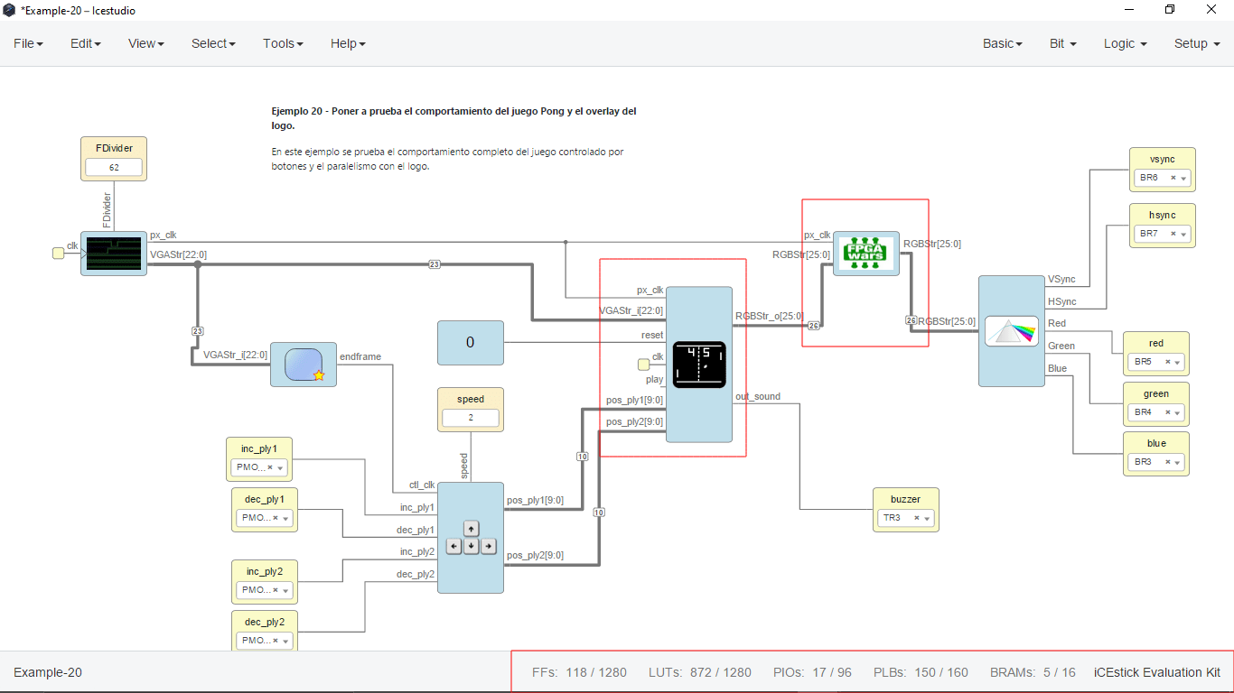
After some understanding of the Icestudio Program of the screen-pong I decided to remove the score showing block of the game so I calculate I can still play the game without the score board in the display.
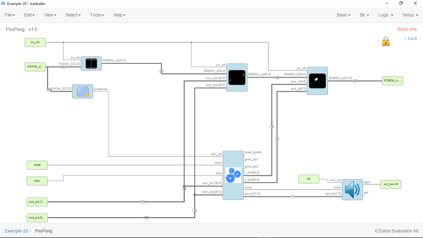
From Inside the game block of the program I removed the score showing program block and reconnected everything else in place. I'm also removed the 'FPGA wars' logo showing block which is not necessary for the game also.
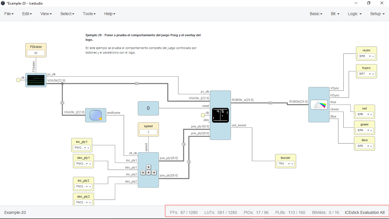
Here is the final game code which is uploaded without any errors and also reduces the usage of program space and other aspects of the Lattice ICE40 FPGA
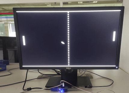
Here is picture of the Monitor running screen pong game from the FPGA gaming console I've created. No its time to focus on the controller,i've program the controller to make it work.
Programing the Gaming controller
The controller is made using joystick so the working of the joystick not like a switch it clearly a 3 point variable resister and shows resistance in those points asper we change the position of the joy stick. normally joystick has two coordinates x,y we only depending on the x coordinates because we only have up and down motion.So here I must make a program for the attiny412 to read the analog value of the joystick and give an output of the 1 and 0 states to the fpga to control the pong game.
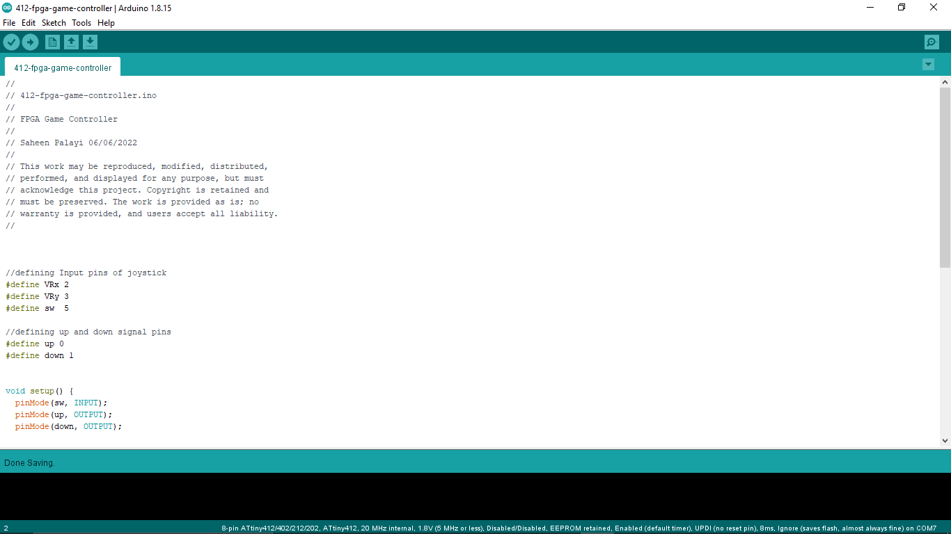
So I've made a program in arduino to just read the up and down action of the joystick and then it perform the digital outputs accordingly through pin 0 and pin 1.
CODE :-
                //
                // 412-fpga-game-controller.ino
                //
                // FPGA Game Controller
                //
                // Saheen Palayi 06/06/2022
                //
                // This work may be reproduced, modified, distributed,
                // performed, and displayed for any purpose, but must
                // acknowledge this project. Copyright is retained and
                // must be preserved. The work is provided as is; no
                // warranty is provided, and users accept all liability.
                //


                //defining Input pins of joystick
                #define VRx 2
                #define VRy 3
                #define sw  5

                //defining up and down signal pins
                #define up 0
                #define down 1


                void setup() {
                  pinMode(sw, INPUT);
                  pinMode(up, OUTPUT);
                  pinMode(down, OUTPUT);

                }

                void loop() {

                  // Checkin the joystick in the up position or not
                  if (analogRead(VRx) < 450) {
                    digitalWrite(up, HIGH);

                    delay(100);
                  }
                  else
                  {
                    digitalWrite(up, LOW);

                  }

                  // Checkin the joystick in the down position or not
                  if (analogRead(VRx) > 550) {
                    digitalWrite(down, HIGH);

                    delay(100);
                  }
                  else
                  {
                    digitalWrite(down, LOW);

                  }

                }
The same code uses for both controller and no changes in the code so programed the both controller using UPDI programer I've made.
Then I made a connecting cable out of some header pins and ribbion wires then connected the joystick controller board to the FPGA like in the picture. Now I'm all set to play.
Let's play the game
Here in the video u can see my left hand playing to my right hand there are nobody in the lab while Im filming this.It was an awesome feel to play the game after all of this journey in the FPGA
The Summery
Thanks to the lock down we got here in India let me explore about the FPGA yet.It's not a thing that we can fit in a one fab week actually. The journy of the FPGA is not ends up here for me like some one sys It's just a beginning.I will explore more about the FPGA in future and also will make my own great projects then will document as well.One of my instructor told me that I can also build entire Microcontroller inside the FPGA. Definitely gonna try out one day
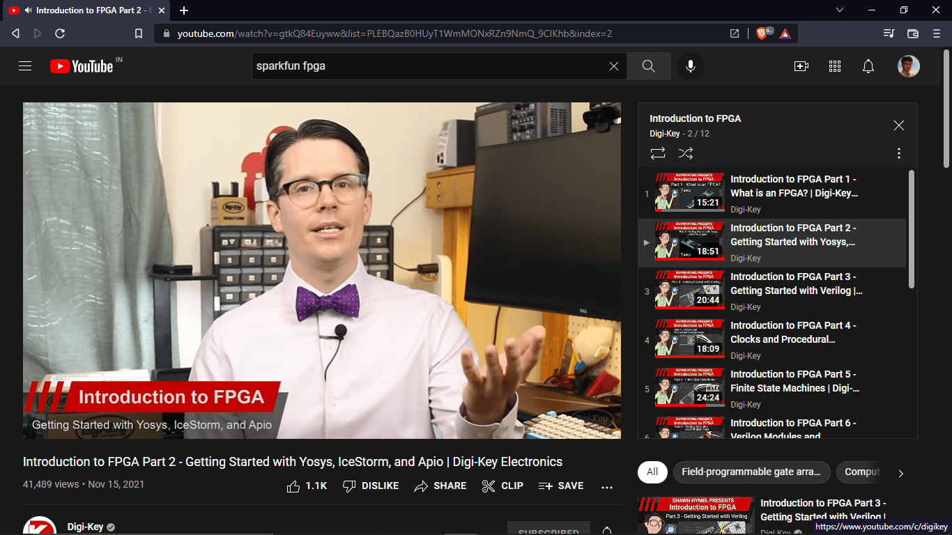
Here is a youtube video series I found During the documentation. It's done by shawn hymel from Digi-Key Youtube channel.The guy is awesome I love his presentations. Find the Link Here.
He also integrating a RISC V CPU core inside an FPGA . A good thing is he also Using the Same Icestick Evaluation board that I've used.
PICK and PLACE CNC Machine
I wasn't sure the FPGA journey I did is enough fo the assignment because the requirements of wild card week assignment clearly sys that to Design and Produce something digital which include CAD and CAM. The reason why I did the FPGA because of the pandemic lock down now we are back in the lab and got some extra time to complete the academy so I decided to do try out the Pick and place machine in our SuperFAB LAB
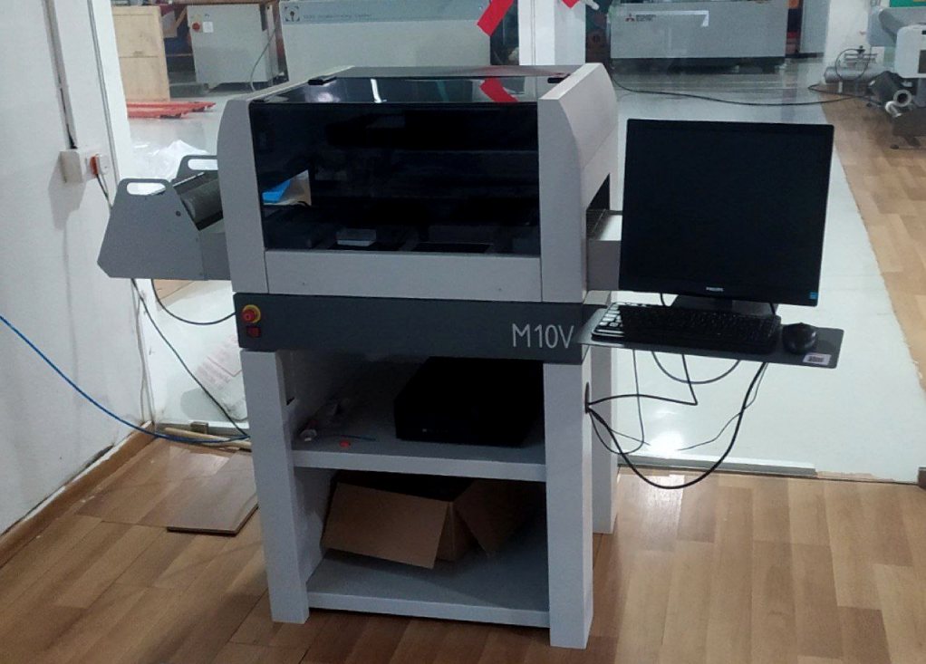
This the machine we have in our lab for the Pick n Place Jobs The machine is called Mechatronika M10V and probably made in Poland and it's a Polish machine.No official documentation available online and found a supplier called SMTnet.
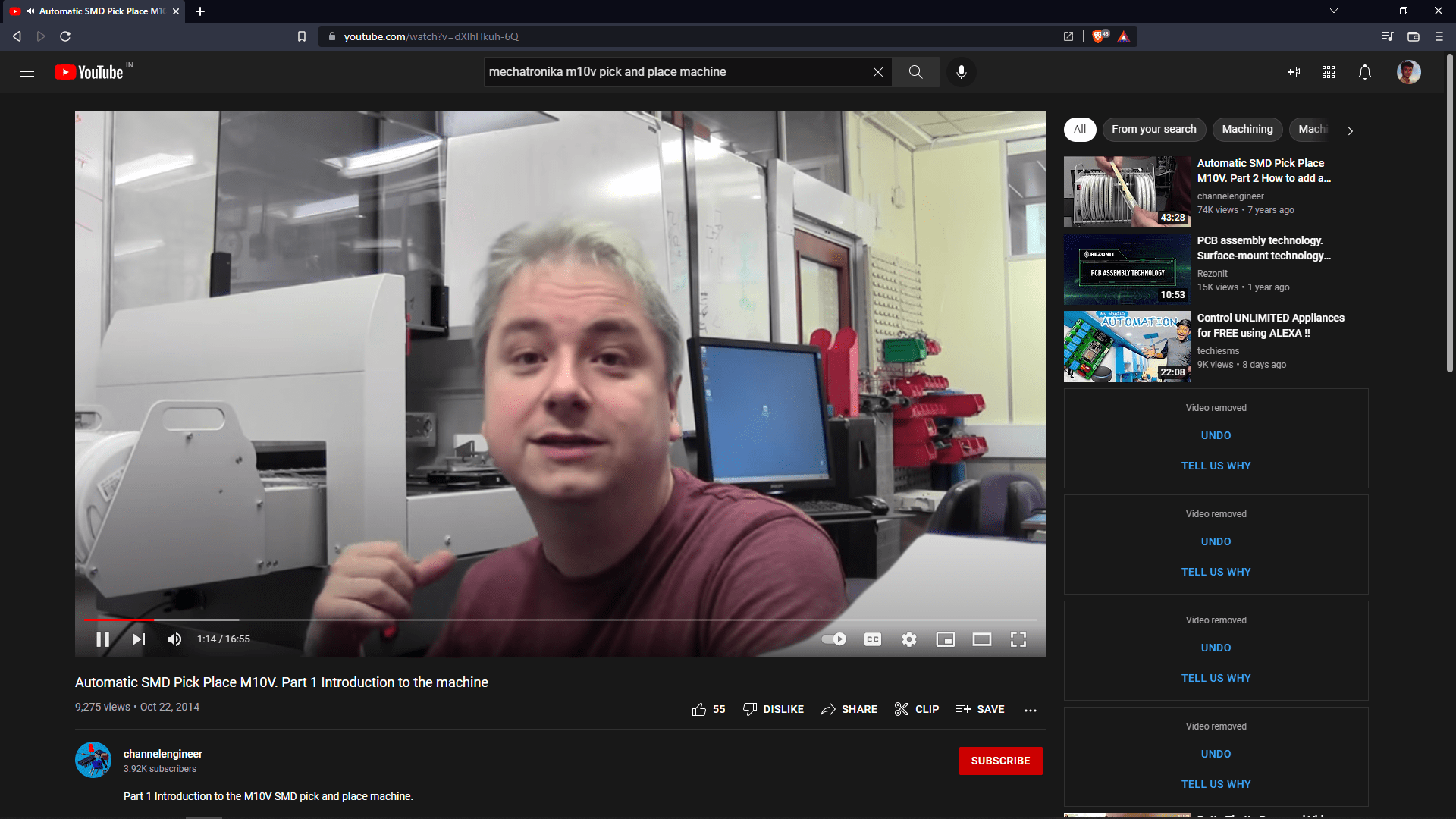
By searching online I found an awesome youtube video series of this machines setup and working by a youtube channel called "channelengineer". one of our Instructor Mr.Rahul S Rajan joined me to help out with the machine because no body in the lab knows the machine's to work I was the first one using the machine.
- Tutorials Found in Youtube:-
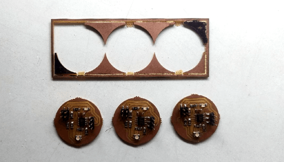
PCB Penalizing for Pick n Place
References
- Fab Academy Wildcard Week classes
- FPGA | en.wikipedia.org
- Lattice ICE40 Software installation Tutorial
- FPGA | Servo PWM in VHDL
- icestudio.io
- GreatScott's Driving a VGA Display
- Screen-Pong github repository
- Screen-Pacman github repository
- www.fpga4fun.com | PongGame in VHDL
- FPGA Video Series | Digi-Key's Youtube channel
Downloads
- FPGA Verilog Programs
- PCB Design Files