Computer Controlled Machining
week 7 Group assignment is to do our lab's safety training test runout, alignment, speeds, feeds, materials, and toolpaths for our CNC machine
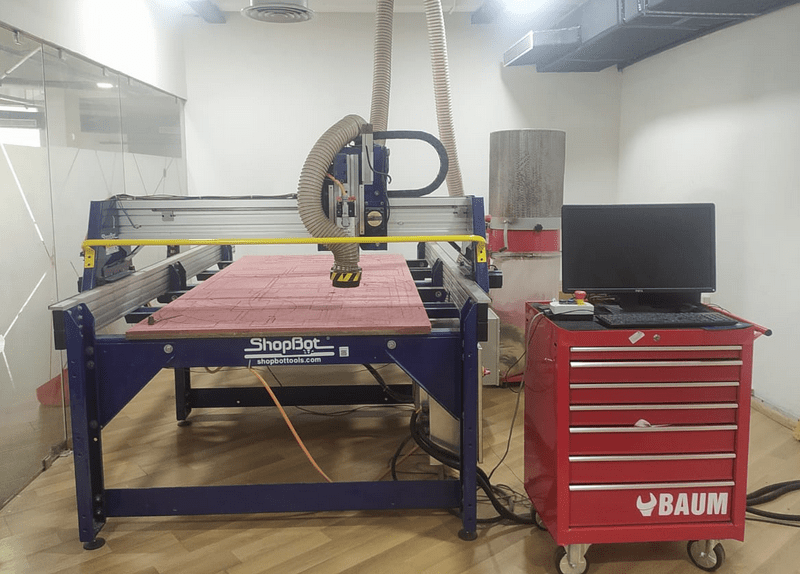
ShopBot
Fab lab Kochi has a 3 axis wood CNC by ShopBot.This is the most dangerous machine that uses for the Academy.Operating a larger wood cnc machine is new for me,never done before with beasts like this .ShopBot has a bed size of 4x8 feet or more and supports material like timbers,plywood,MDFs and some soft Aluminum etc...
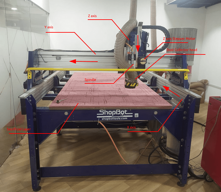
The below picture shows the spindle and its moving axis directions and other parts as well.
A PC is attached with the machine for easy Machining.which include the ShopBot driver and V carve Pro CAM Softwares etc..
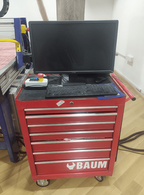
The red color table shelf is the tool box of the ShopBot where all the tools like endmill bits,collects,other tools are stored.There is an 3 manual control interface of ShopBot placed top on the toolbox table which include start,Reset buttons and Emergency Stop button.
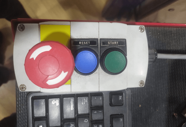
these switches for resetting the connection of entire machine and also for starting the spindle.If something gone wrong We have to hit hte Emergency stop switch
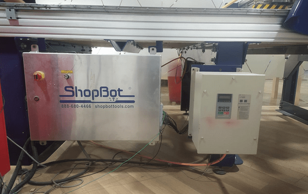
This is where all of the main controls section of the ShopBot embedded which include stepper drivers,power supplies,VFDs etc...
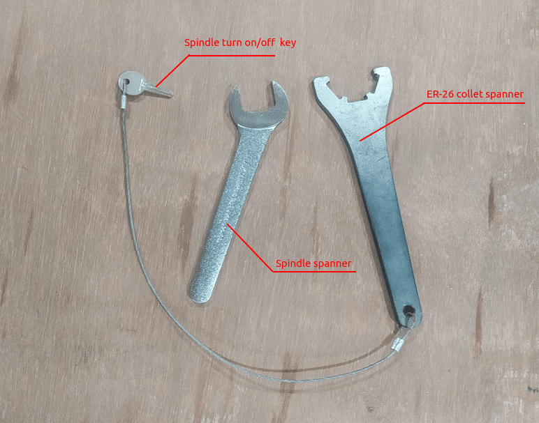
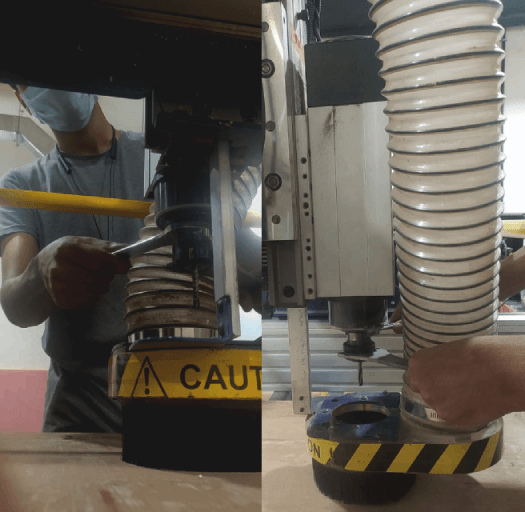
These spanners use for attaching endmill bit to the ShopBot spindle.One for holding the collect chuck one for holding the spindle shaft.An electric switch key connected to the Collet chuck spanner for safety.That's u cant use the spanners without turning of the spindle.these key lock can be found on the control box of the ShopBot
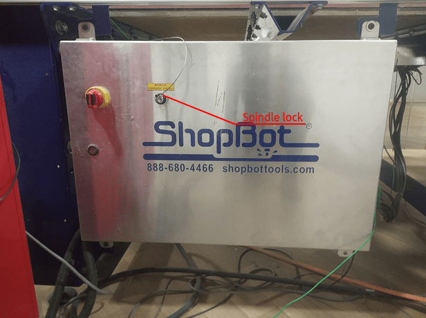
So usually the lock need the key to turns on always and we cant use the spanners without turning off it , So nobody gonna get hurt from the spindle while attaching or changing the Endmil tool in cas any accident. awesome safety feature!.
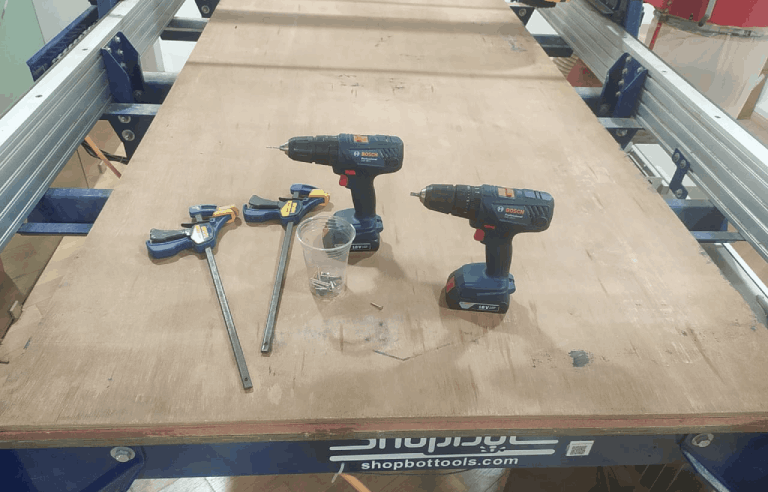
Here is the picture of the hand tools and the clamps used to hold the stock above the sacrificial layer. Any in-proper stock placing or any lose ends of the stock can leads to vibrations, Endmill damages and other dangerous accidents as well.
Safety and Precautions
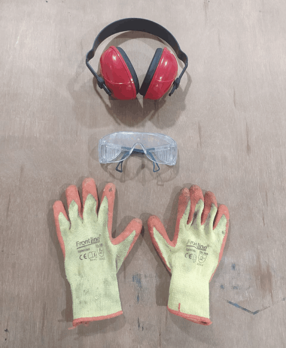
When it comes works with machines the Safety of the worker or operator or who ever near by is biggest concern and the person must follow the safety protocols in a LAB. Fo us the Shopbot is the beast in the academy syllabub very noisy and dangerous when something goes wrong.
Press fit Testing
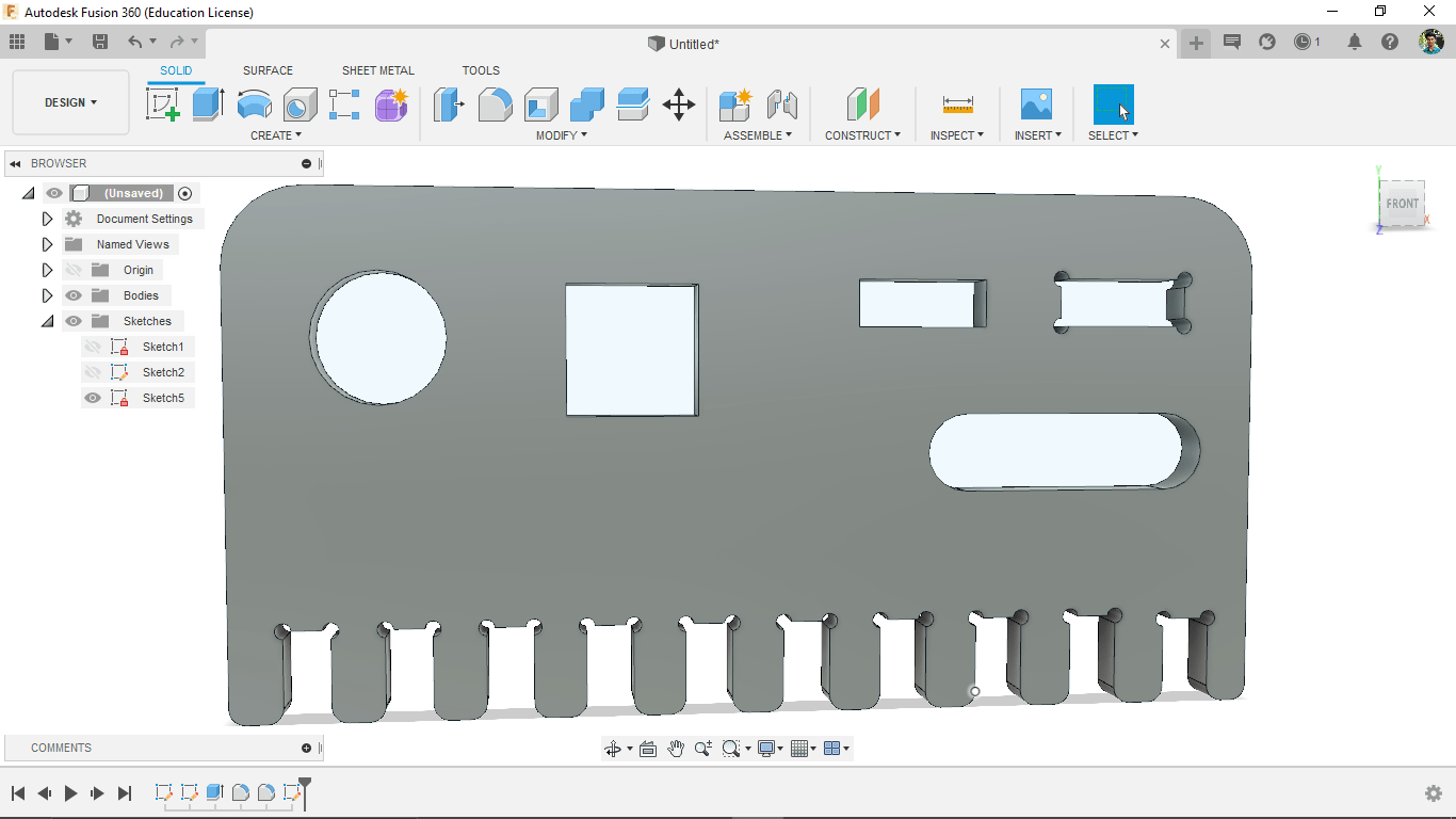
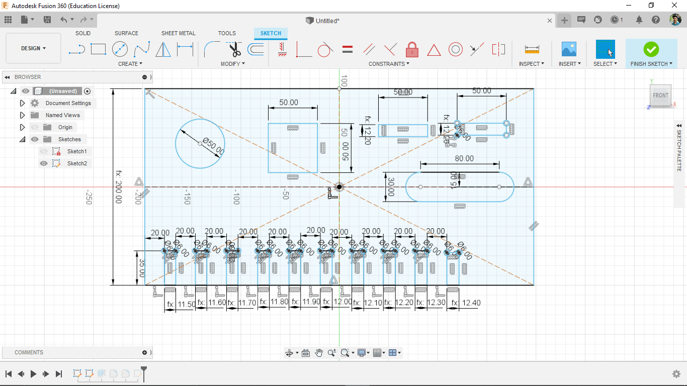
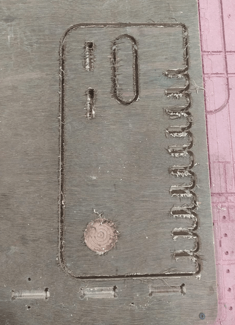
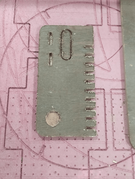
For understanding the machining rules of ShopBot we done a test cut which include pocketing,Inner-cut,outer-cut,wood joint press fit etc... So,We designed a test jig with some holes and press fit key on fusion 360
The material thickness that provides in kochi fab lab are 12 mm and 18 mm thick plywood sheets of 8x4 foot.so We the design was done in parametric according to the thickness.we done our test in a pice of 12 mm plywood
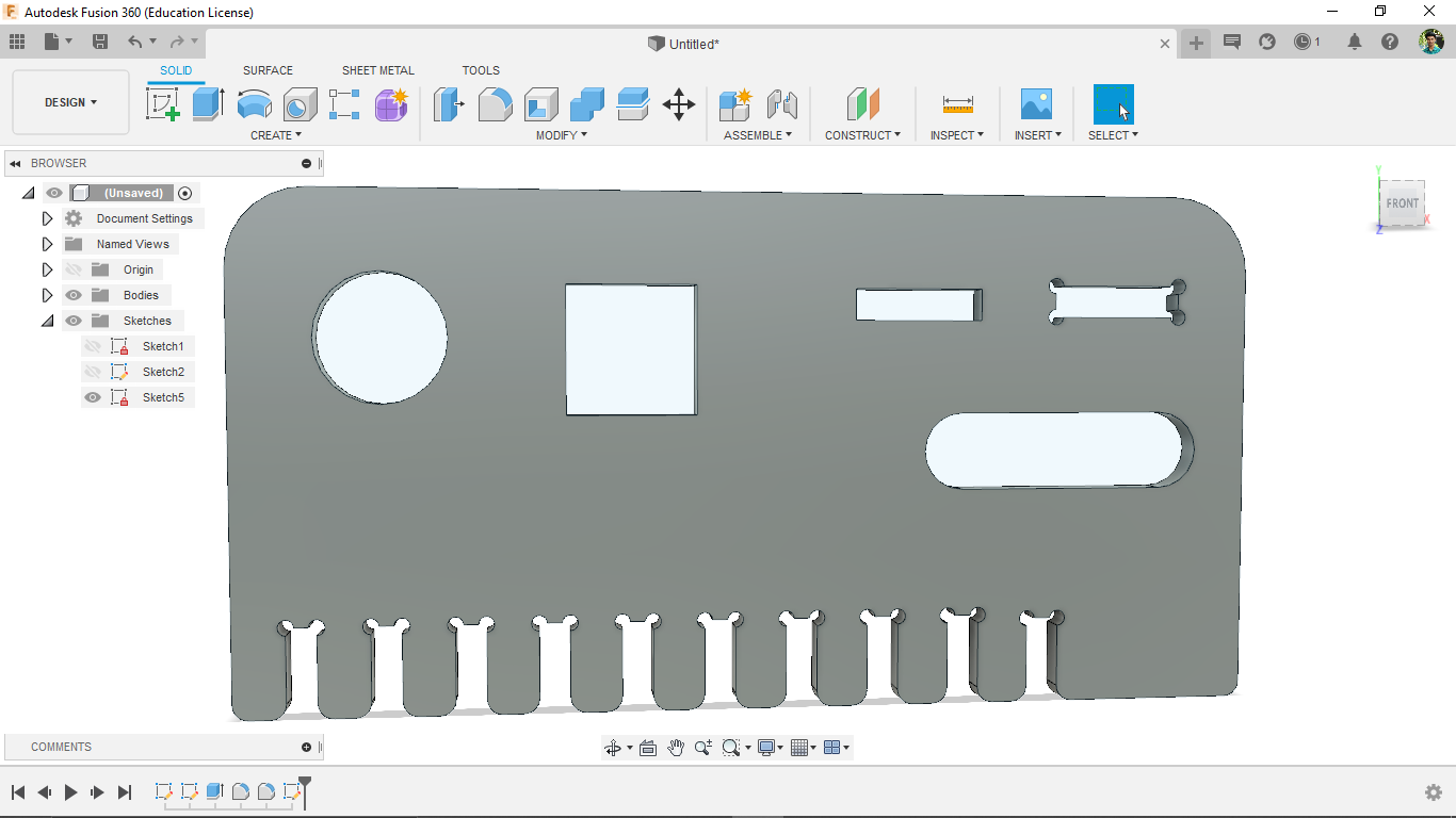
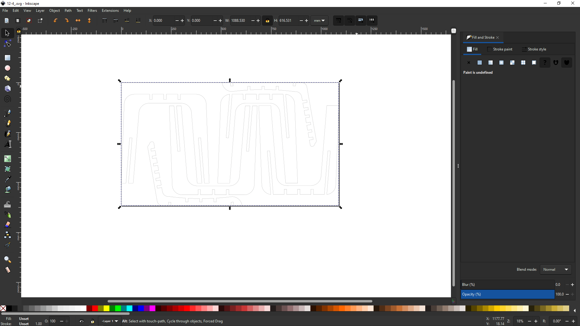
The below picture shows the dimensions of the pockets,holes,and the wood joint jigs etc..
This test file created with parametric design which we can use to test various thickness materials from same design . we exported the file as DXF from fusion 360.
Then we opened in to V carve Pro software and set the thickness of the material 12.7 mm then clicked ok. the play wood we actually selected for the test is 12 mm standard but the wood is old. so because of the moistures in the air the thickness expanded so we got 12.7 while measuring as average.
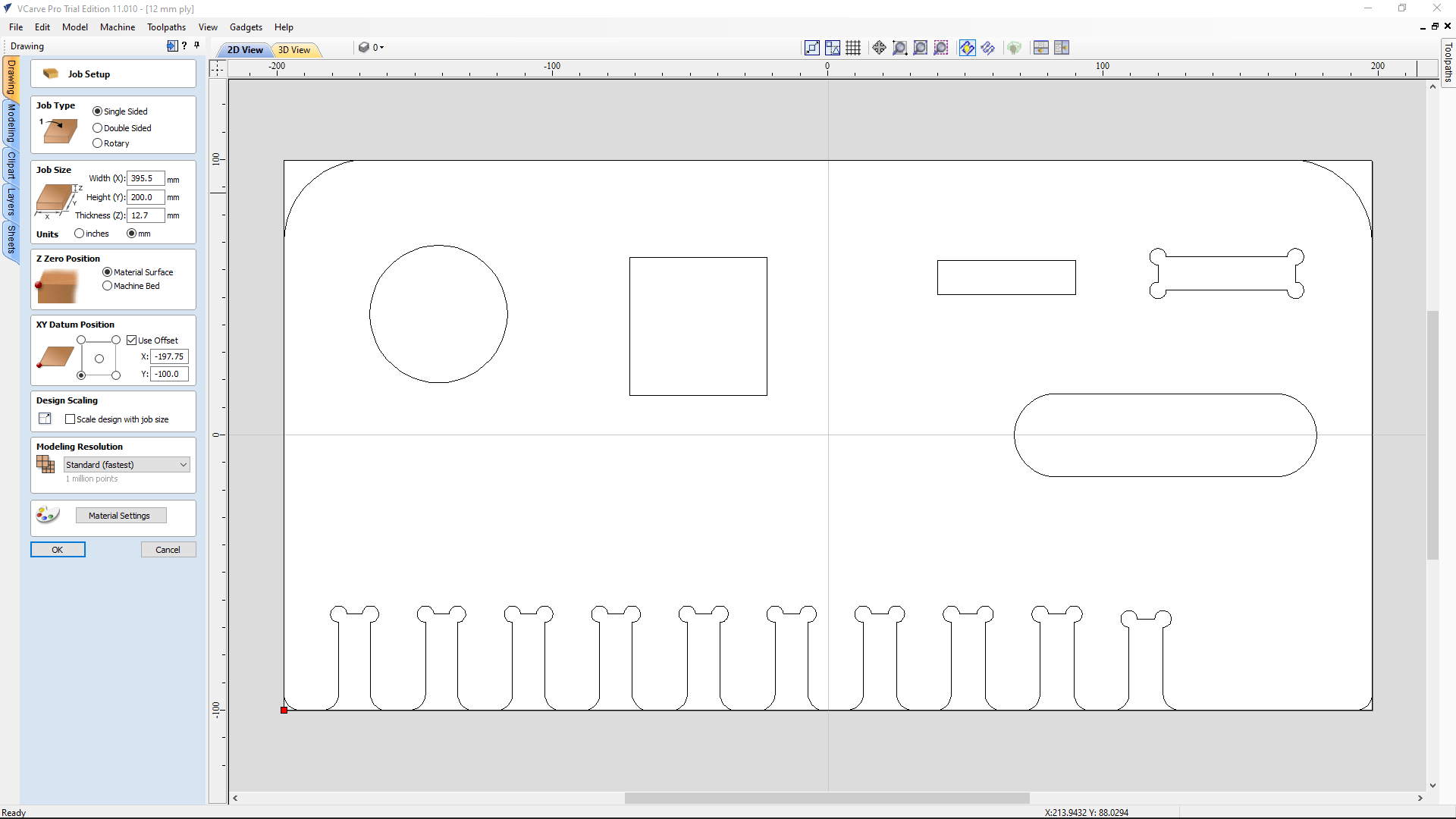
Then the DXF vector file came up in a window with vector editing options so if we need to edit the file we loaded it's possible in v-carv pro. Then we pinned Toolpath side menu from top left.
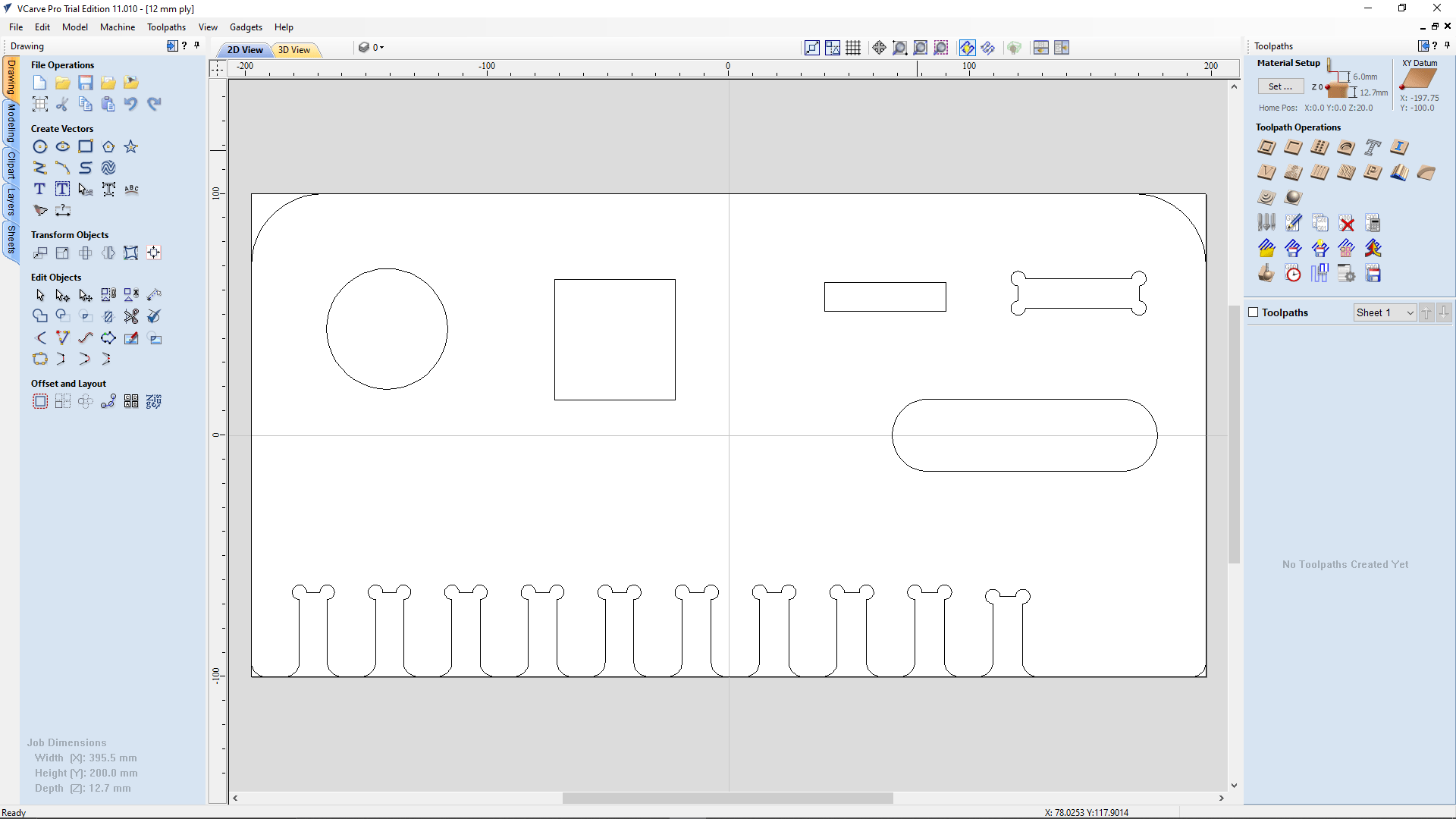
At the toolpath menu lots of toolpath creation tools available and also we edit the material setup by hitting the 'set' button on the top.
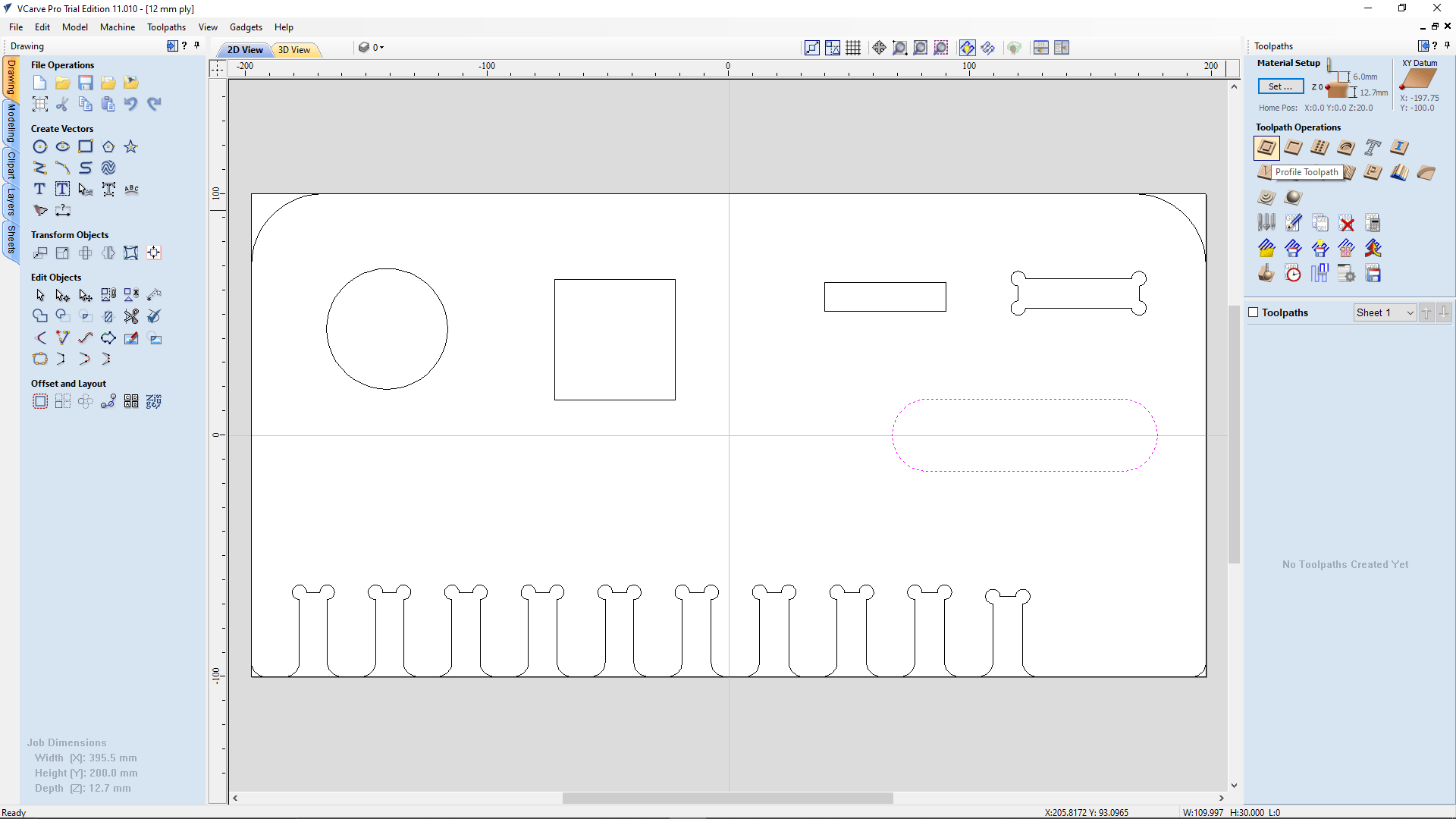
Then we started to create tool path firstly we selected the rounded rectangle shape then clicked the 'profile tool path' option under the 'toolpath operations' in the Toolpath menu.
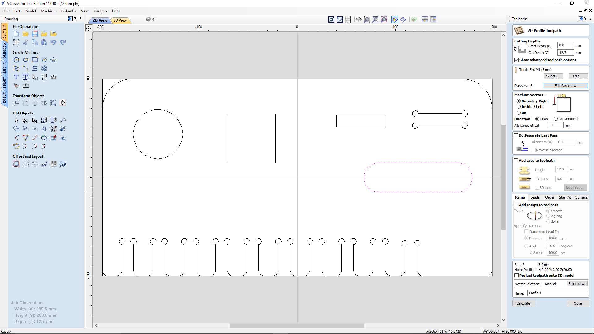
Then it's open the '2D Profile Toolpath' setup for creating the tool path .Firstly we set the cut depth same as the material thickness and selected the machine vector operation as 'Outside / Right' because the inside part is our target.
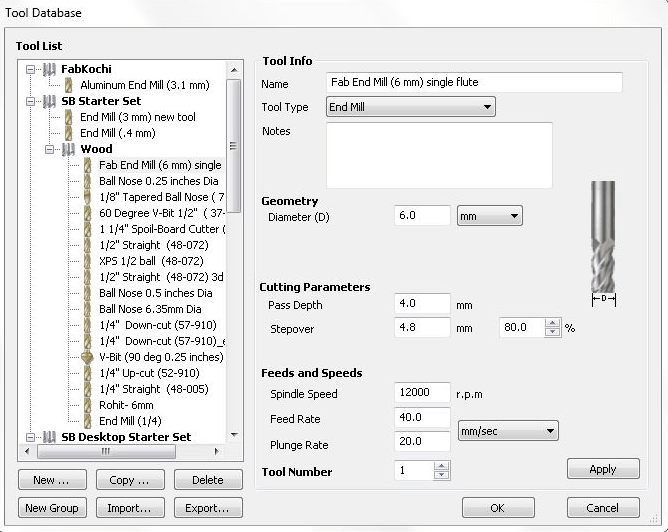
We also selected the tool as FAB 6MM single flute from the tool library, The above figure shows the parameter of the tool we are using.
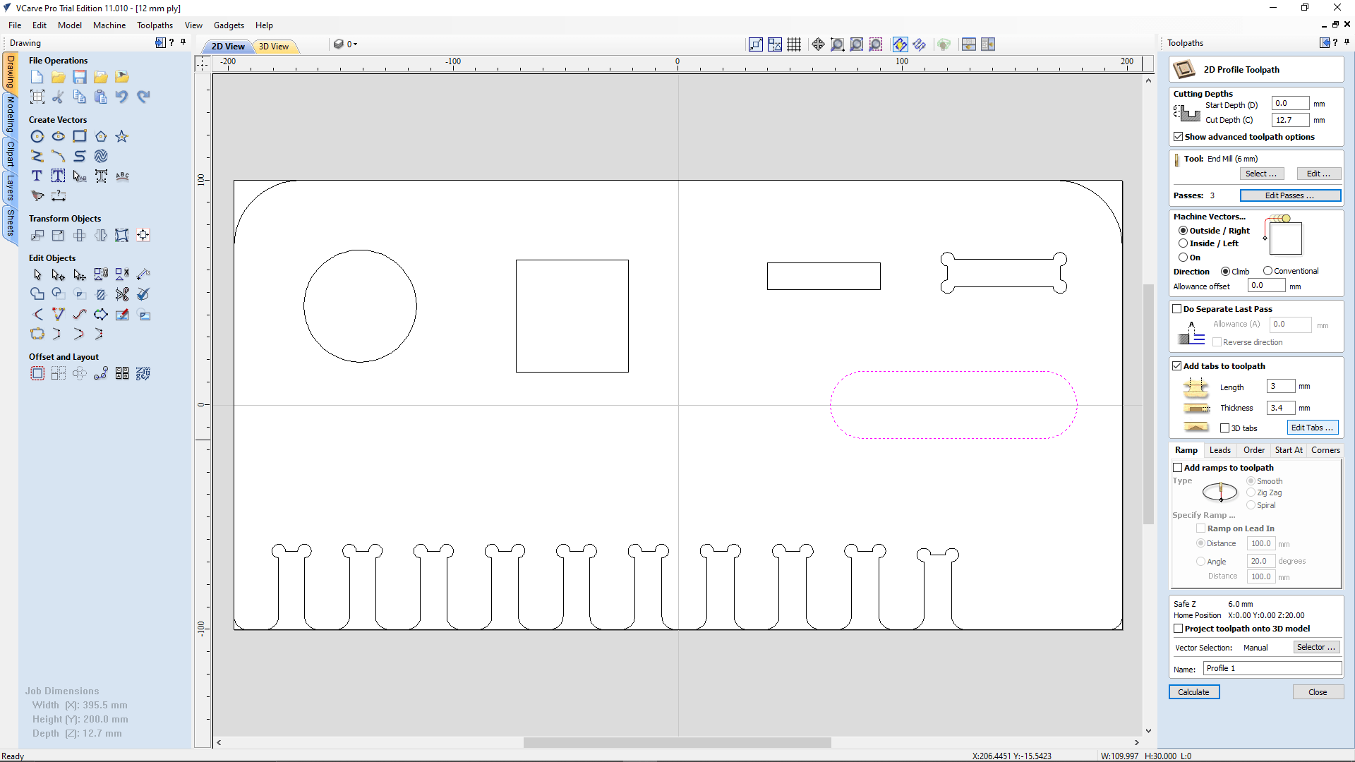
Then we enabled the tabs menu and clicked on edit tabs to add the tabs around the object to be cut. Tab length we gave was 3 mm wide and 3.4 mm thick. This Tabs feature gonna help us to keep the cut part keep in the material for avoiding any machine accident and also helps to cut properly.
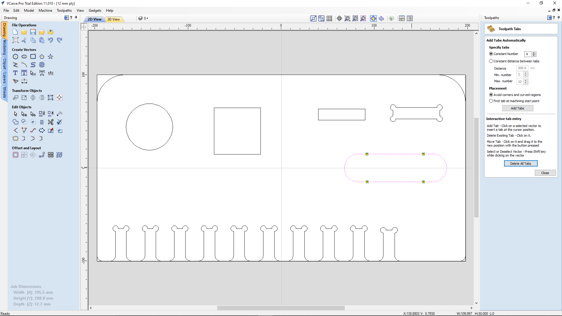
we added 4 tabes around the object by manually and we can also go for the automated tabbing just select the number then click on add tabs.But, sometime the automated tab will come in curved surface which is required more attention to clear the tab chip after cutting.
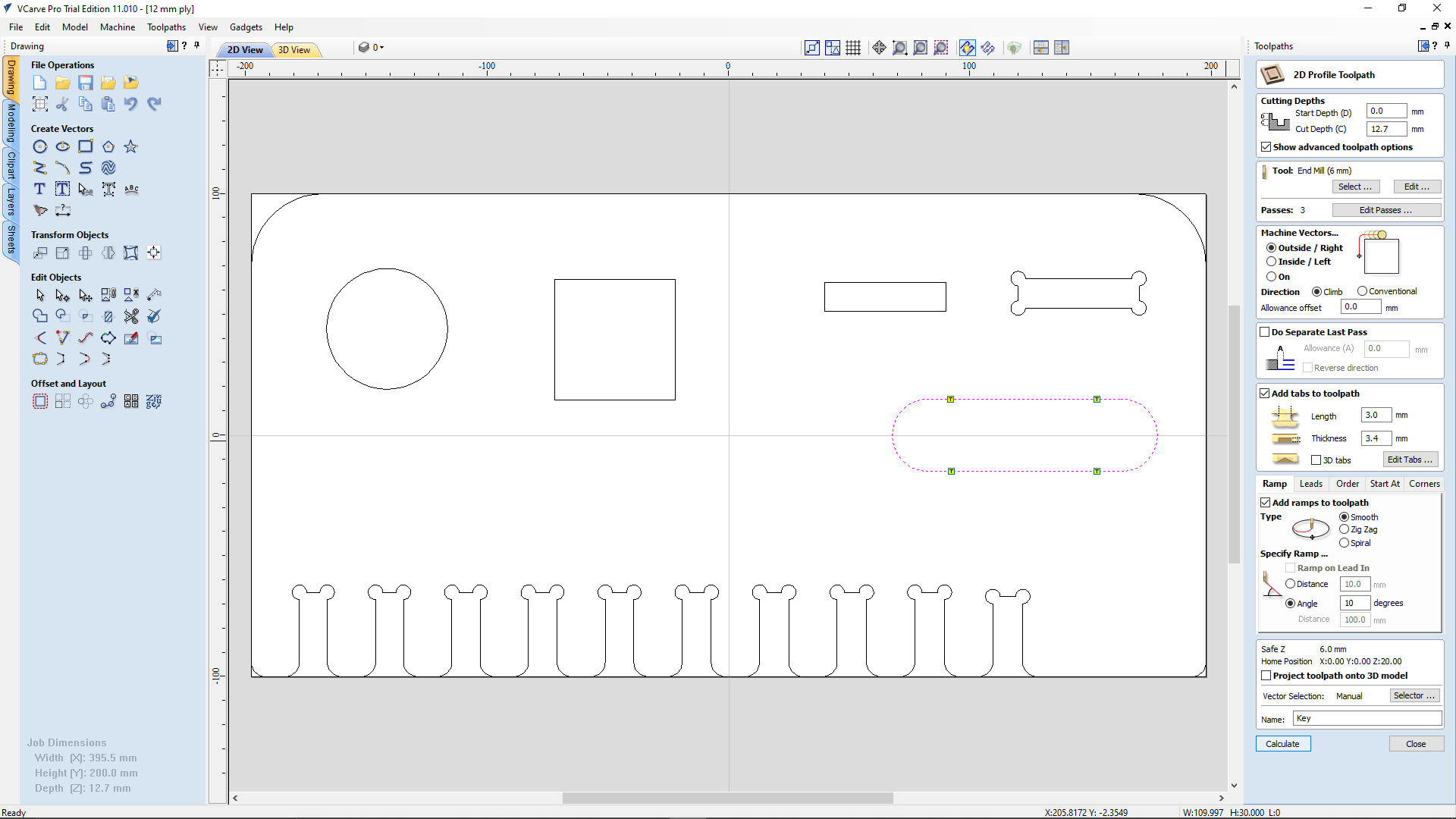
Then we enabled the Ramping menu and opted smooth ramp type at 10 degree angle.Then we gave a name for this path as "Key" and clicked the calculate button.
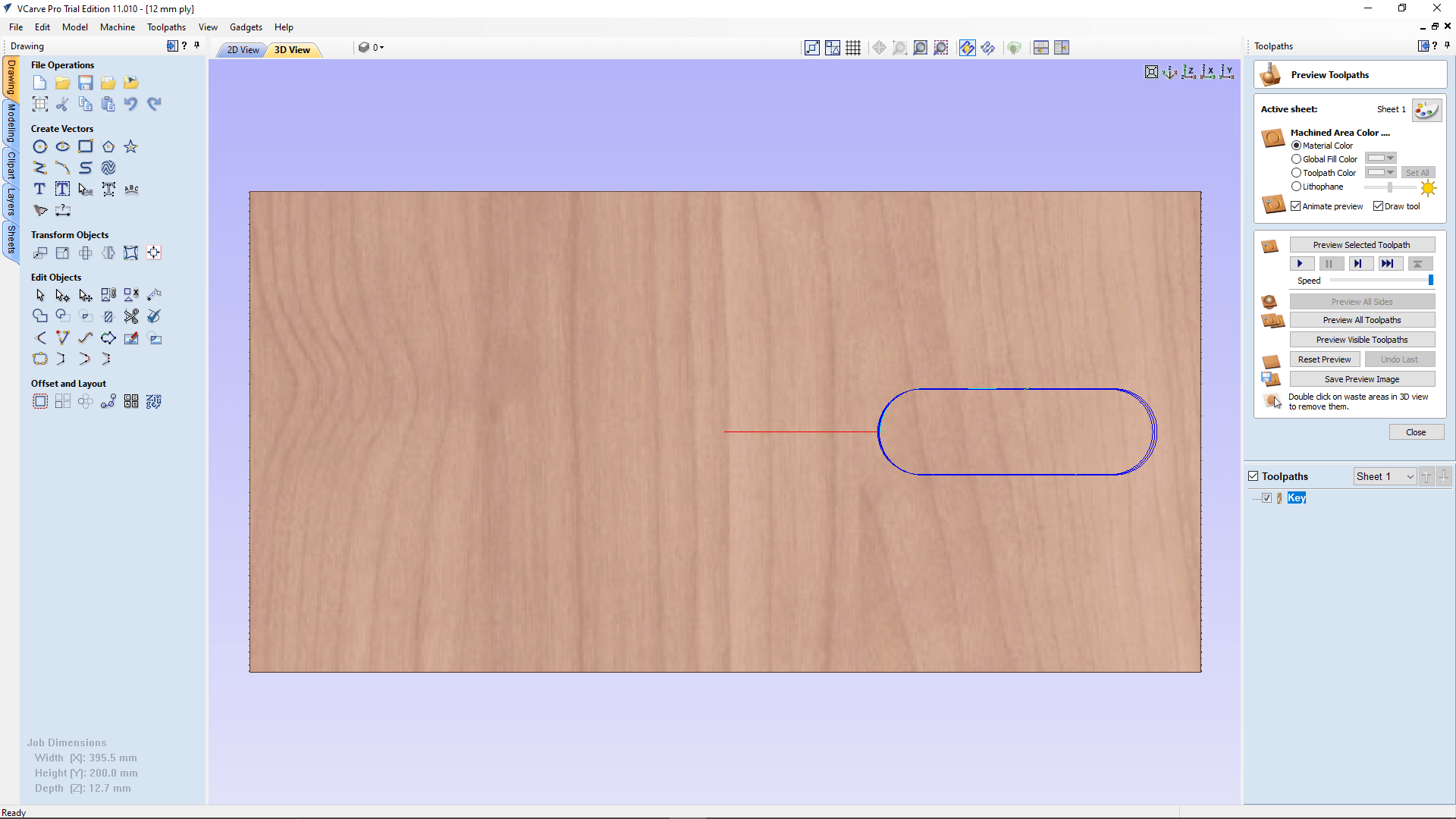
After clicking calculate V-carve pro navigated to the 3D window and simulation setting to check the simulation result of the toolpath we created.
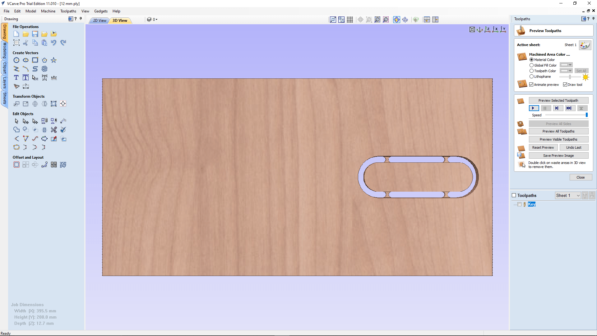
So this was the result after we play the simulation we got 4 visible tabs and promising final cut in the simulation.
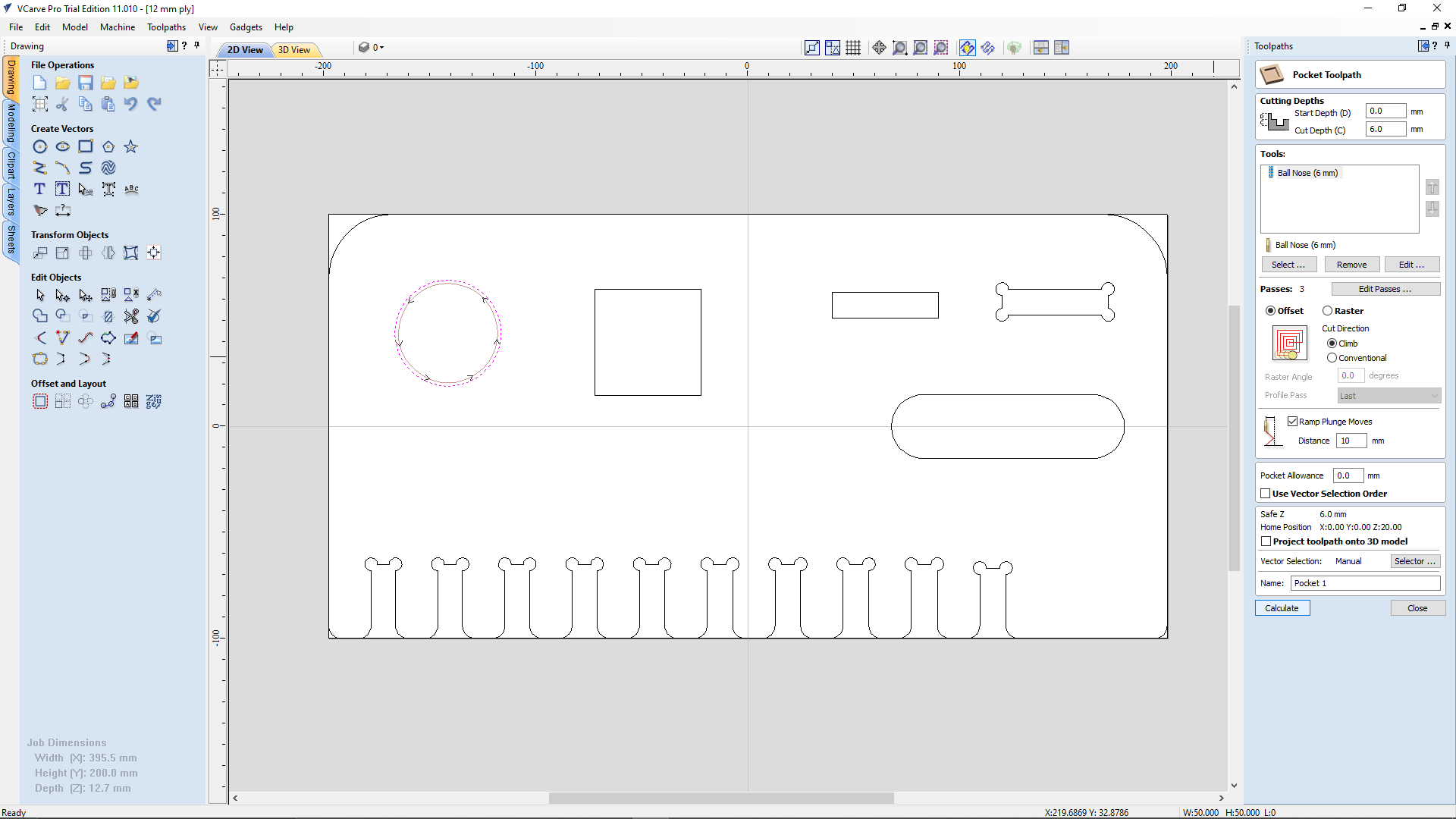
So next we selected the round shape for cutting pocket.This time we selected "Pocket Toolpath" from the toolpath menu and set the cut depth 6mm. And then we selected the tool same as for the 'Key' toolpath ,added ramp in 10 mm distance.
After the simulation here is the results it was really beautiful to watch the toolpath simulation for the pocket creation with the 6mm Endmil. It's doing like a spiral path!.
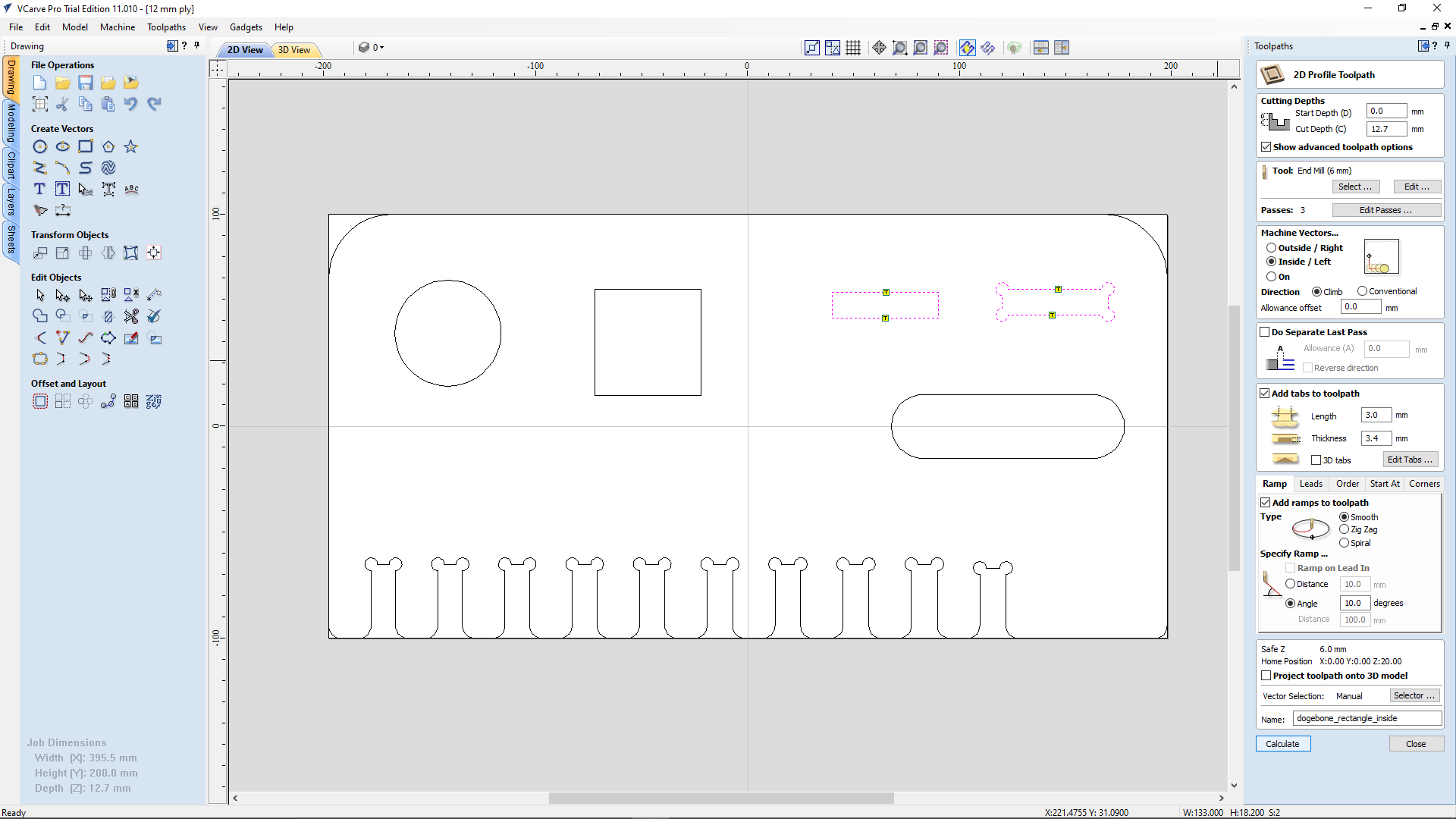
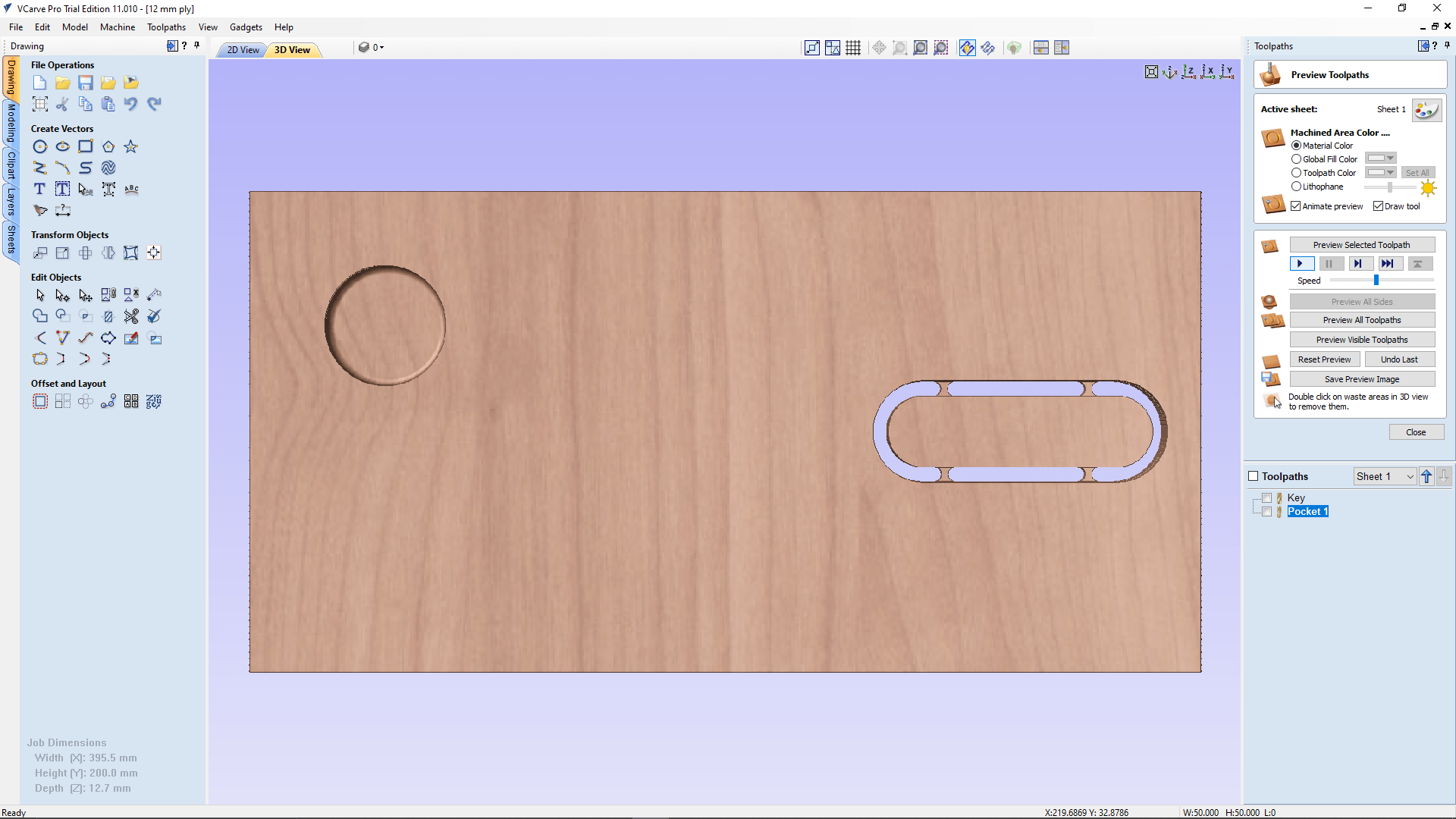
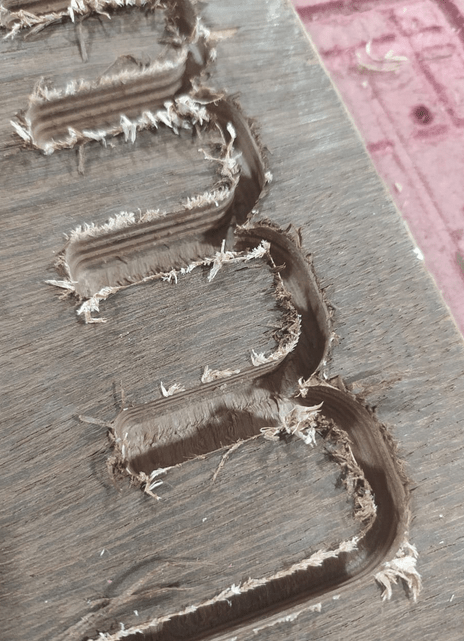
As next we selected another tool paths for the square holes to compare with dog-bone and without dog-bone. This time we opted an Inside cut / left option for the 2D Profile Toolpath setup
We setup everything else same as that we used for the 'key' cut toolpath generation. and we got the simulation results like in the picture. The dog bone from the design was missing in the simulation!
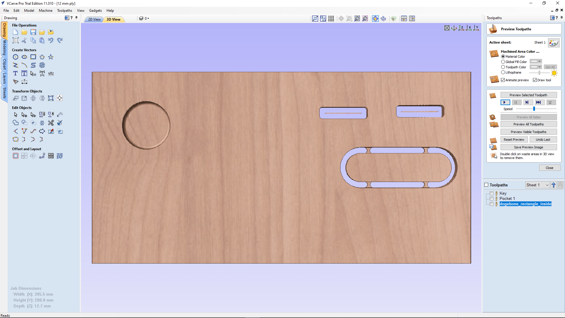
We understand that, it is too narrow to have the tabs inside those rectangle shapes.So,we decided to remove the tab based own our instructor's suggestion. The inside part is not gonna do any damage and also it is an unwanted part.
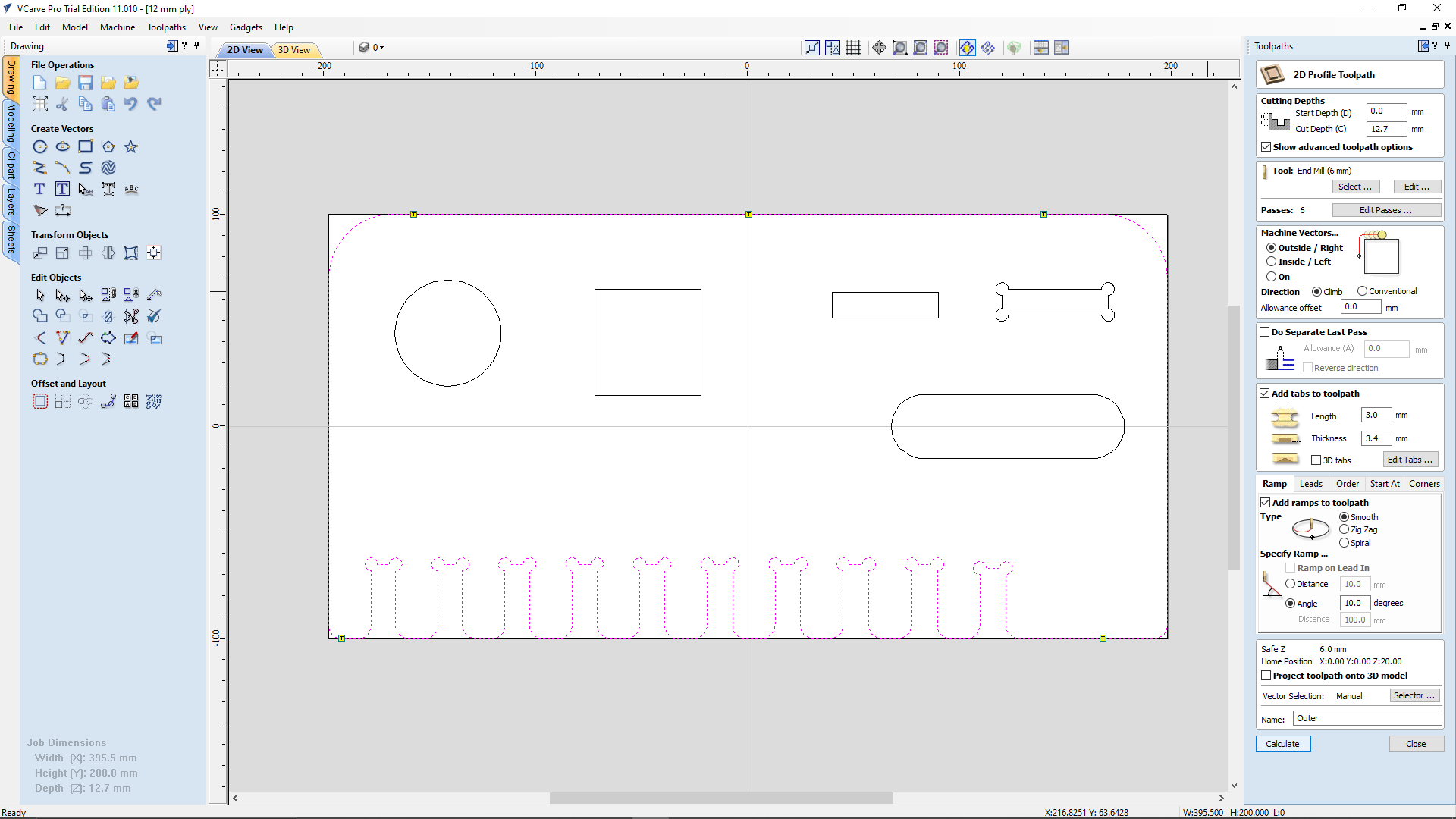
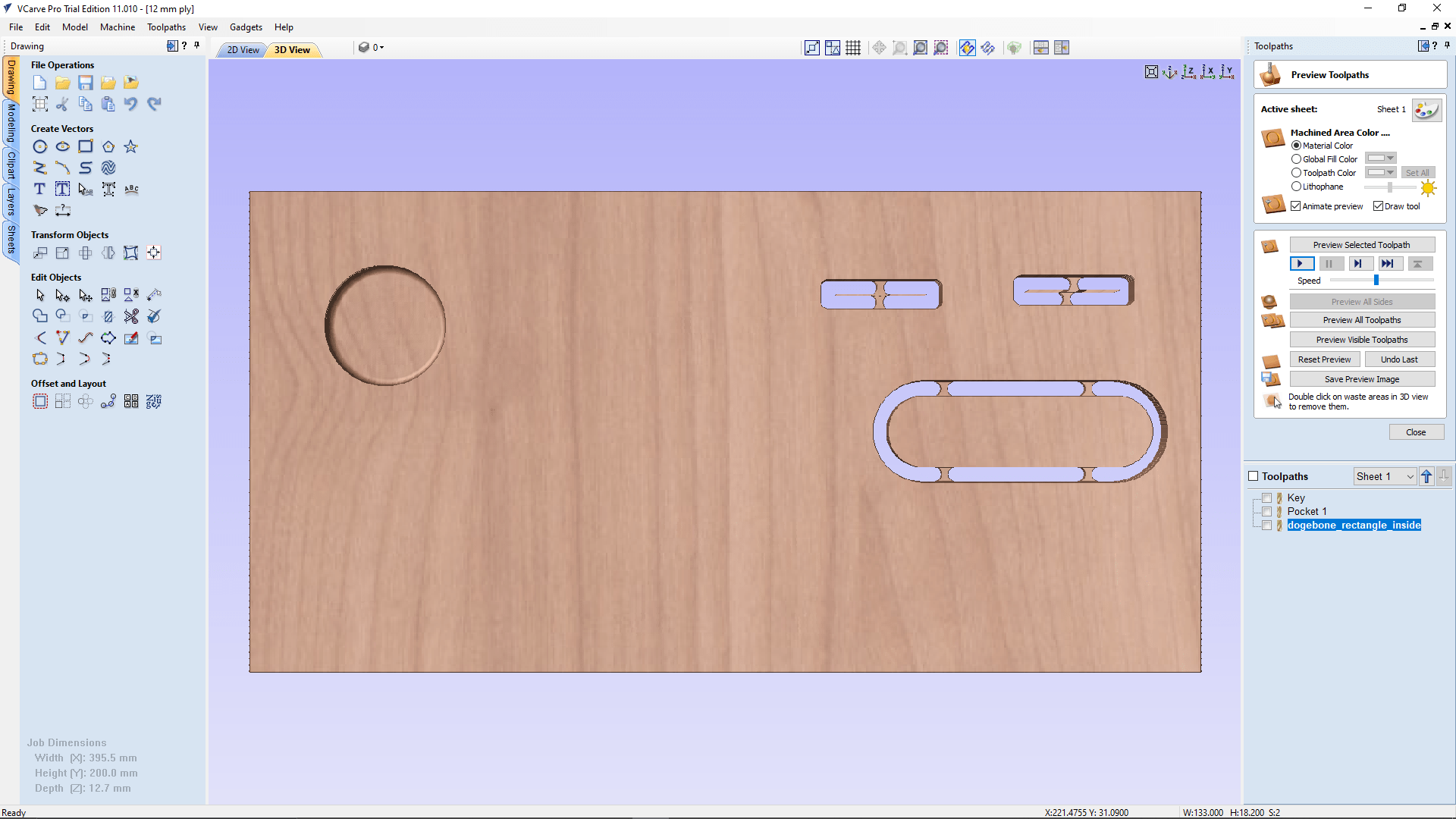
Then we setup the 2D profile cutting for the outer boundary of the test jig design. The setup is everything same as the key toolpath setup also added more tabes around it.
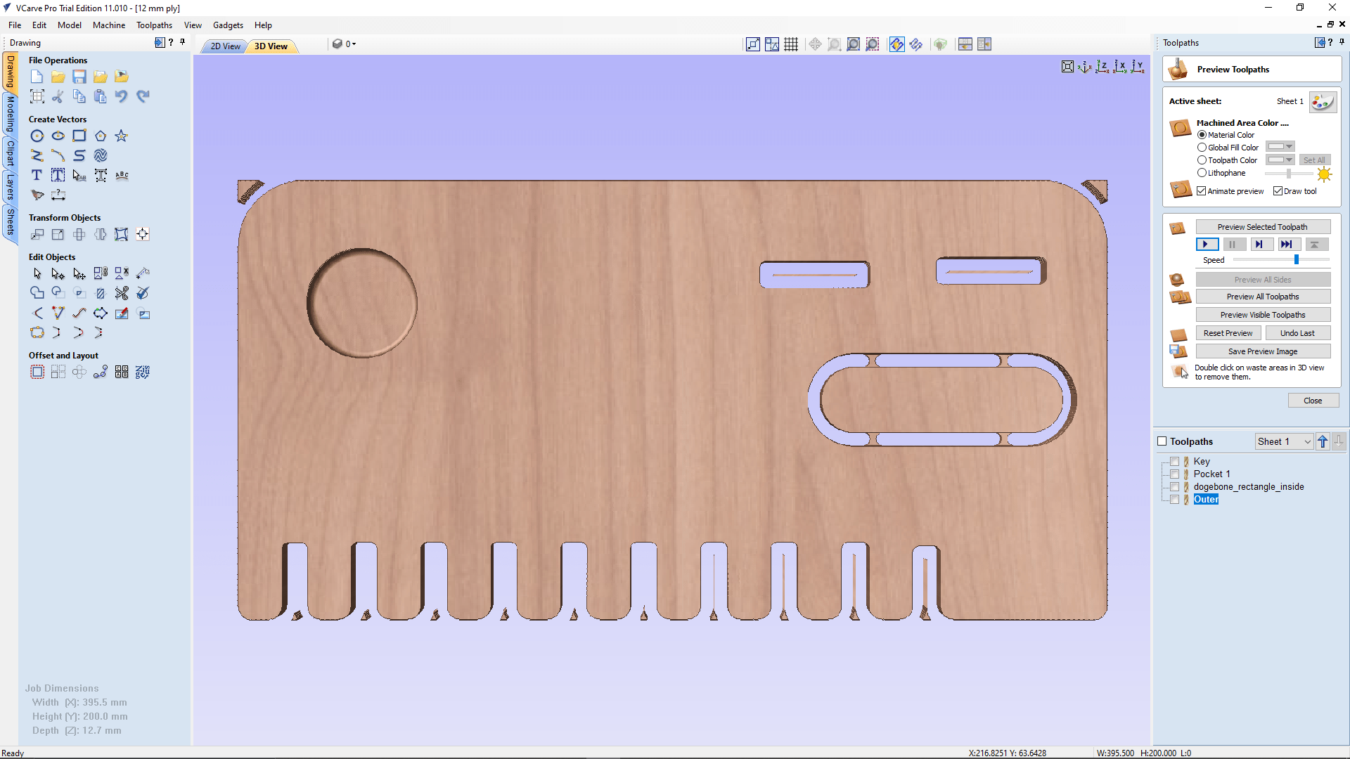
here is the final simulation of all the part we can see that there is no tabs around the design because we didn't set up the length and width of the stock while the material setup in V-curve. our Instructor told us all the tabs will be there it's not a problem for the test cut practice.
After the designing we exported the sketch of the 3D drawing face to DXF format and loads in to the V carve Pro software in the ShopBot PC
After loading the material on the bed we starts to set origins of all axis,starting from x,y .We sets the X,Y origin manually at the corner of the material we loaded .
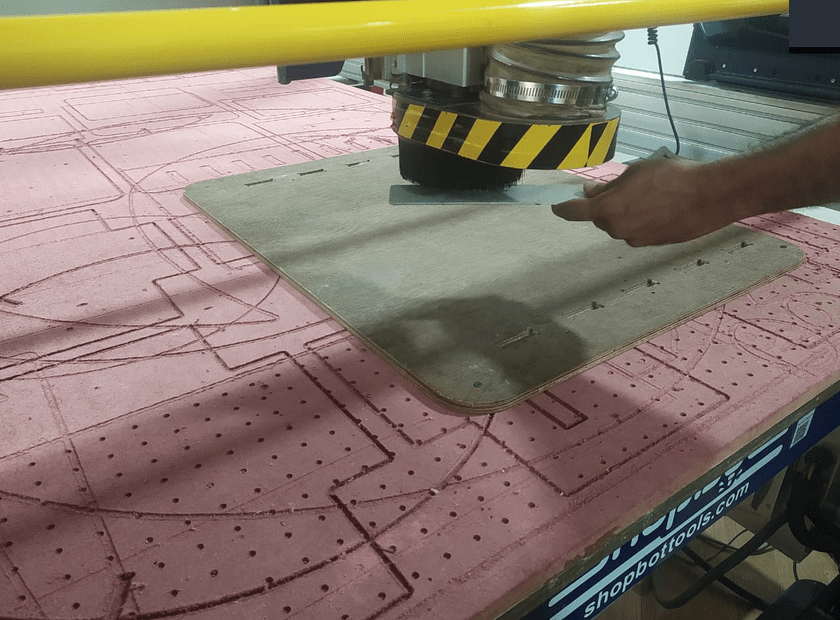
for Z probing we can set either manual or auto probing.ShopBot has a auto z probe feature.A wired aluminum plate which connected to the controller used for z probing so first we checked wether it detects any contact or not.That's for making sure the z probe working or not .other wise there is a chance that it gonna break the bit.
then we paced o top of the work stock and also under the endmill.It gonna slowly lower the z axis till it touches the plate
while the z probe came down we pause the machine and made sure the plate is directly under the end mill,then we continued the machine
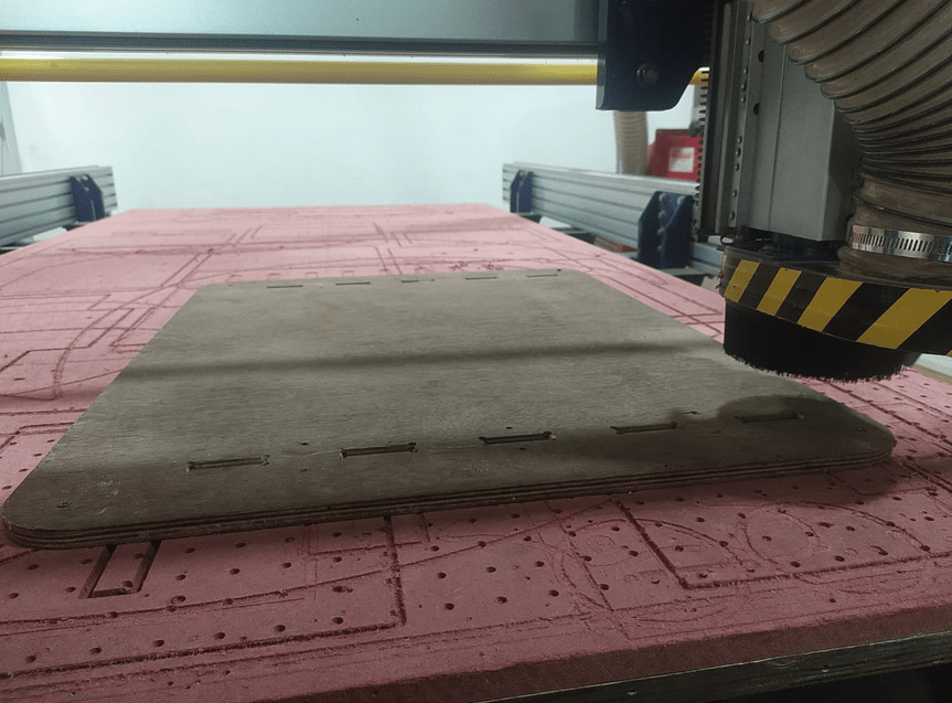
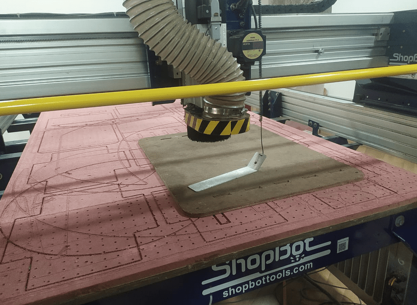
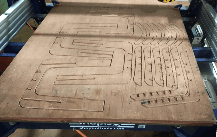
After the probing the machine is ready to cut we moved the machine back to home and started to cutting the press fit test file
After done the cutting the machine went back to home and turned of the spindle it self then we checked the result and we found out that it didn't cut through.
we realize that we forgot to measure the material before loading to the ShopBot bed . so we increased the cutting depth to 13 mm by editing the tool path and ran the machine again
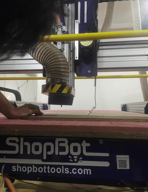
This time All went well and the results are better, we taken it out from the Stock material by breaking the tabs using a chisel.One of us got a scar by wood chips while taking the cut part out so remember the safety,Wear the wood safety glows
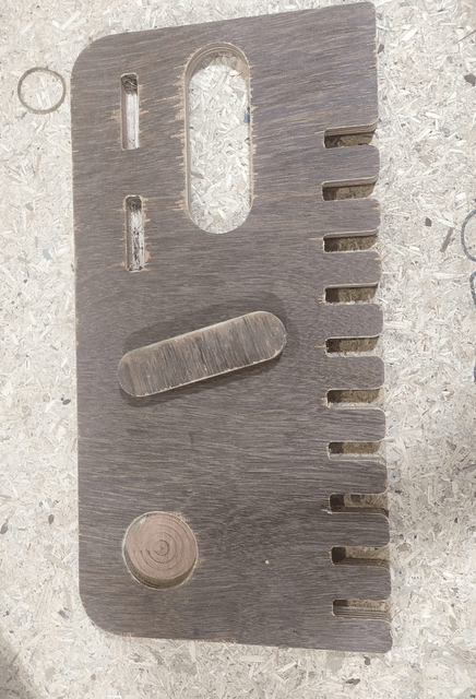
Then we sanded everything using a 100-120 Grade SAND paper and also using a FLAT File then finally used the sander machine for a better finish surface without removing too much material
Then we tried to insert the key in the different joints
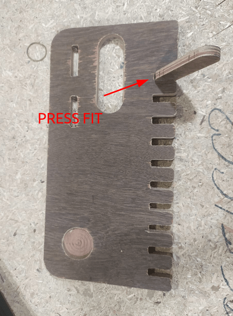
The key perfectly fits in the bigger '12.4 mm' slot with a good press fit.Actually it must be loosen in the slot but then we found out there is an error with the end mill too that we used for cutting.The endmill isn't exactly 6 mm
week 7 assignment is to make (design+mill+assemble) something big (~meter-scale)
extra credits: don't use fasteners or glue , include curved surfaces
Designing the Big
This week is one of the big week and we have to design something big like man sized object.According to the assignment requirement I should design something big and machine then assemble.
I searched over the academy documentations of previous students and many of them did furniture most of them interesting.But I know I'm not a furniture Maker any way I gave it a try
One of my instructor shows this beautiful website called opendesk.cc which provides an uni work platform to organize ,design and sell beautiful CNC furniture's in some countries. I found a chair design from open desk and I take that as a inspirational design to design and build one my own.
Idea to Design
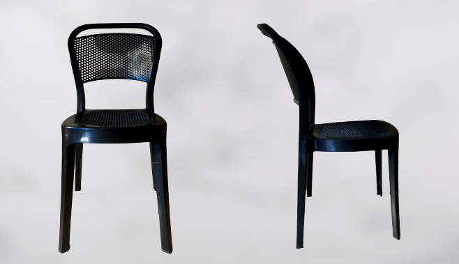
I found this plastic chair in my home so decided to take some mesurments from it to get an idea of sitting positions and angles,width in between legs of the chair ..etc.
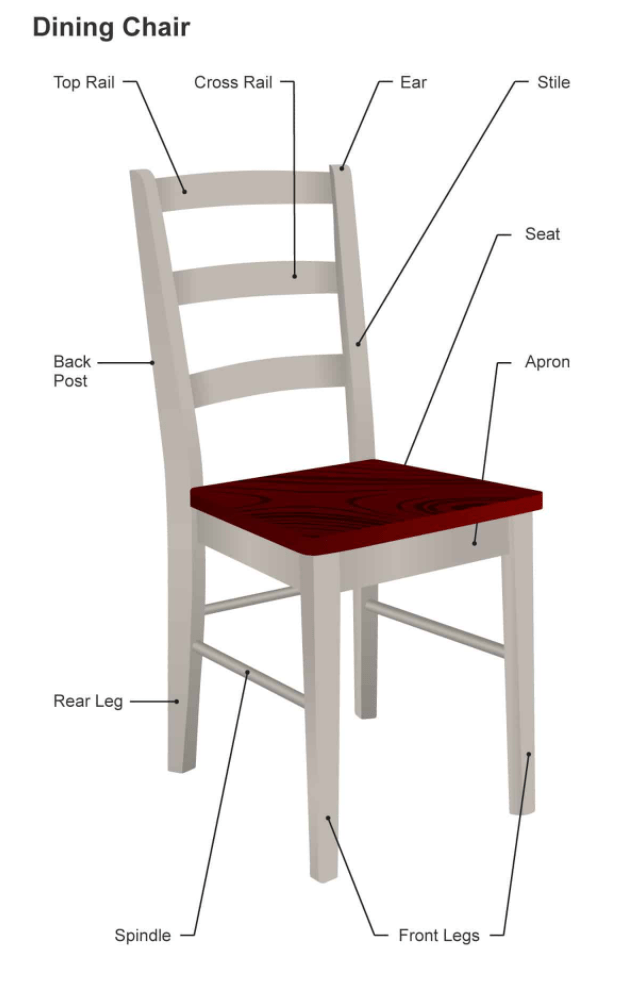
Here is the picture of a typical chair which showing all the component in details of regarding a chair design. this helps me to explore more in engineering manner .
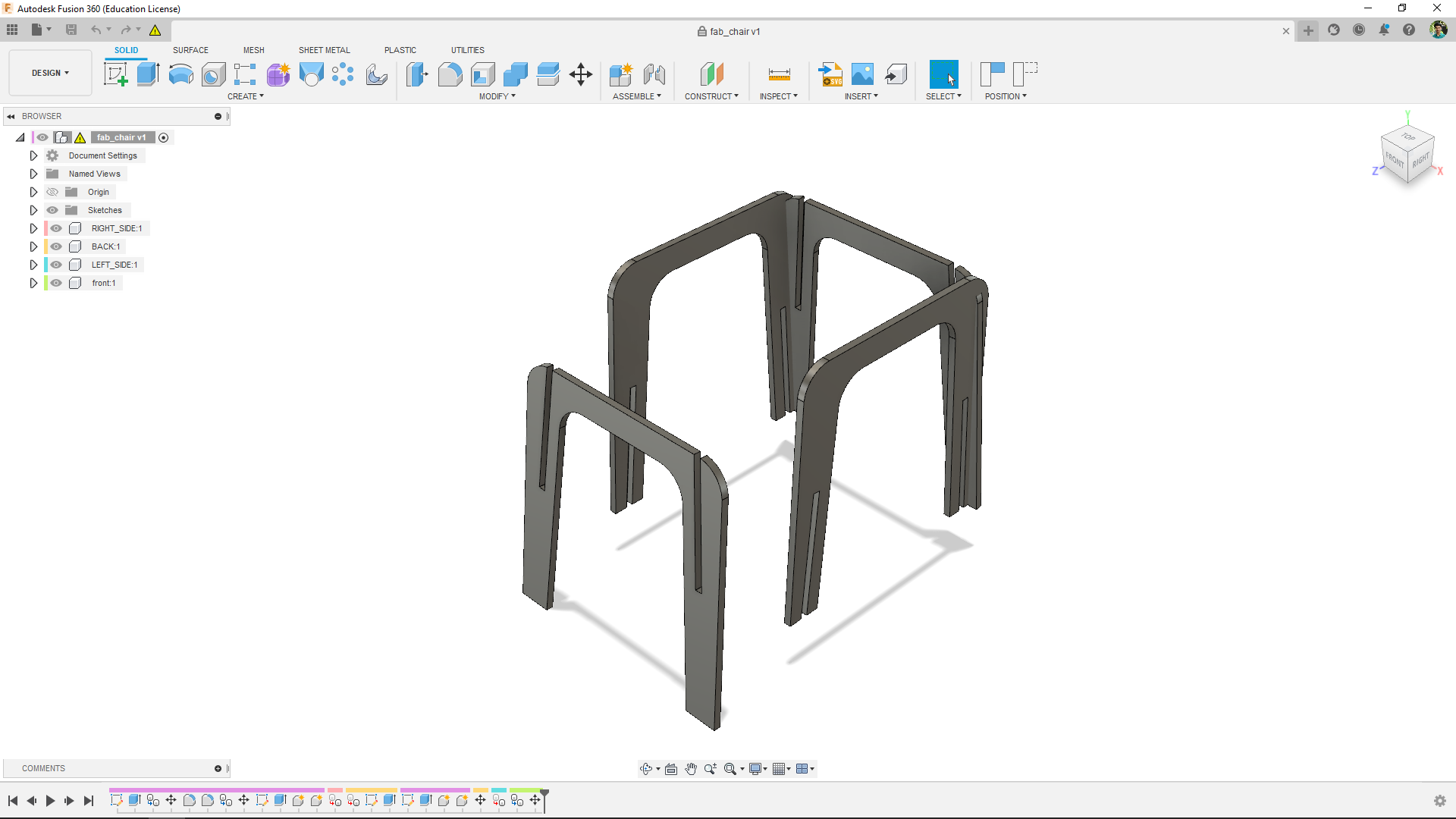
Based on the measured details and inspirational ideas I managed to draw an Interlocking legs of the chair in fusion 360. I'm using 12.4 mm play wood for this design
Then I exported the leg as dxf file to cut and test the interlocking works as expected. Because I faced a joining problem while designing in fusion but, It went well.
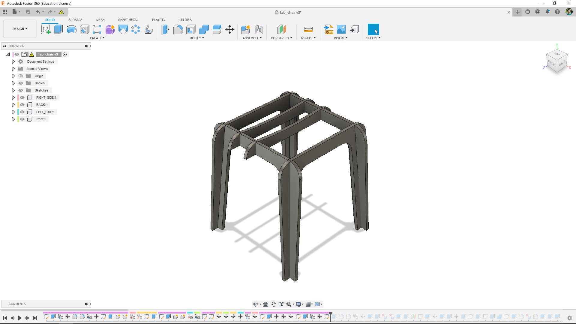
After that I continued the design by adding crosses across the legs for strength and stability
From those crosses I added a 100 degree Back posts for supporting our back while we sitting on it. ha.. ha.. I know that's why It's called chair.
Then I added some ribs as cross rail and its a curvey part in the design.so I added up to 6 wooden curvy ribs part all the back post is too thin to support a man I hope Its work well!.
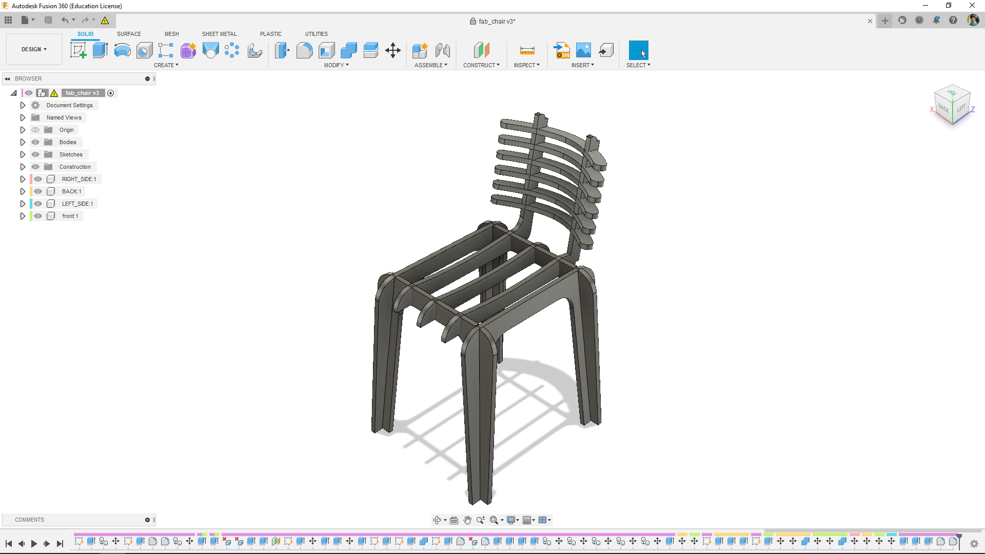
While designing I thought the design was not ok . felt like something over so, I reduced the width of the chair for better look.
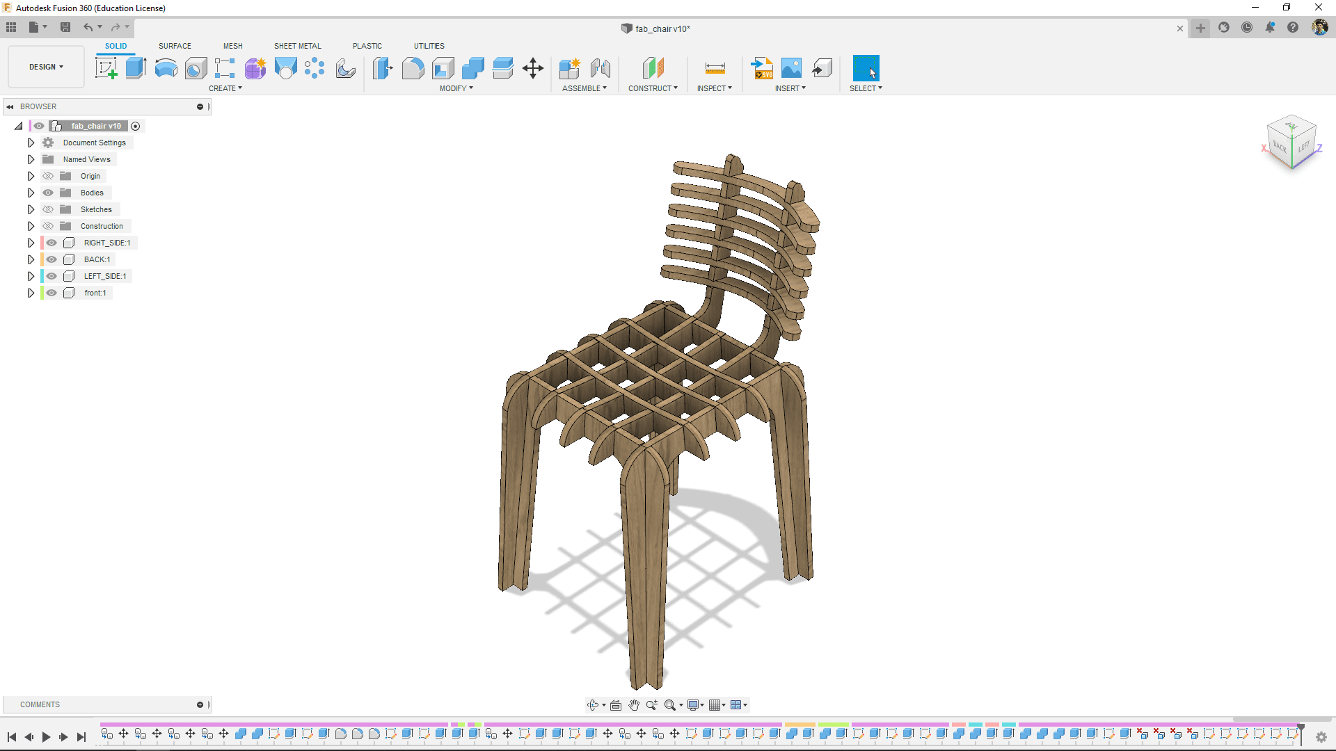
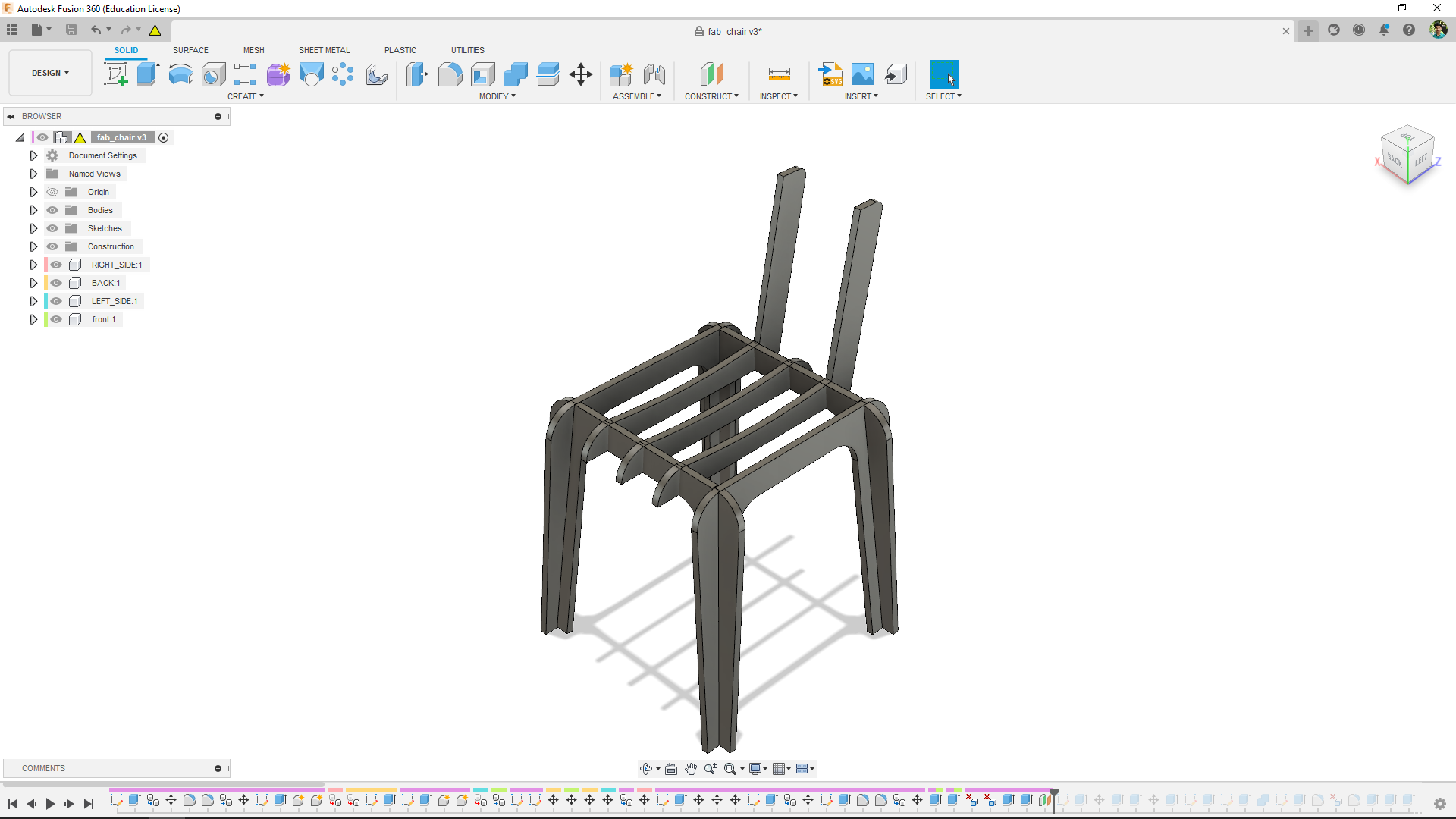
After reducing the width of the chair added 3 more crosses perpendicular across the legs and the first 3 crosses.Then I gave a wooden color for final rendering
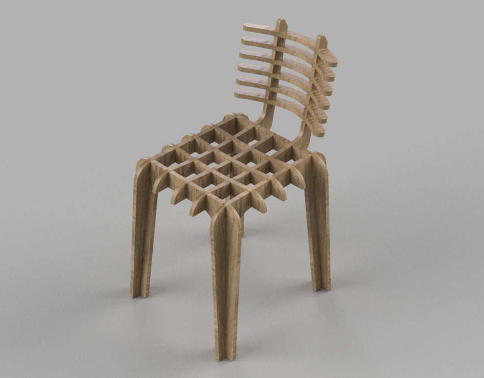
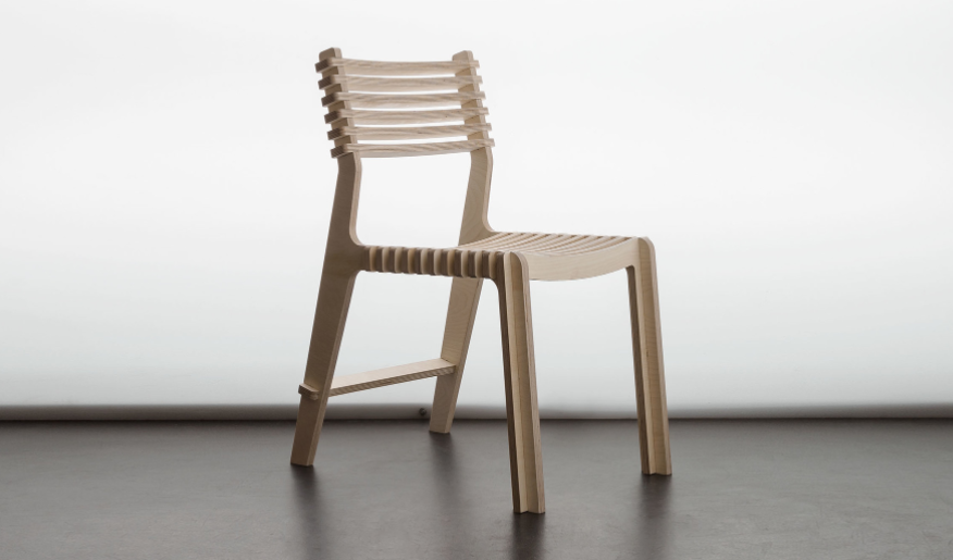
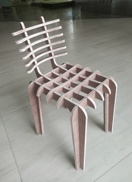
Here is the rendered image of my fab chair which all set for fabricate.
Testing in Small
So I completed the Design in time now its time to test.I'm going to cut the design in a big machine with big material which is more expensive to do than the previous weeks so I need to test a the design is oky in a cardboard
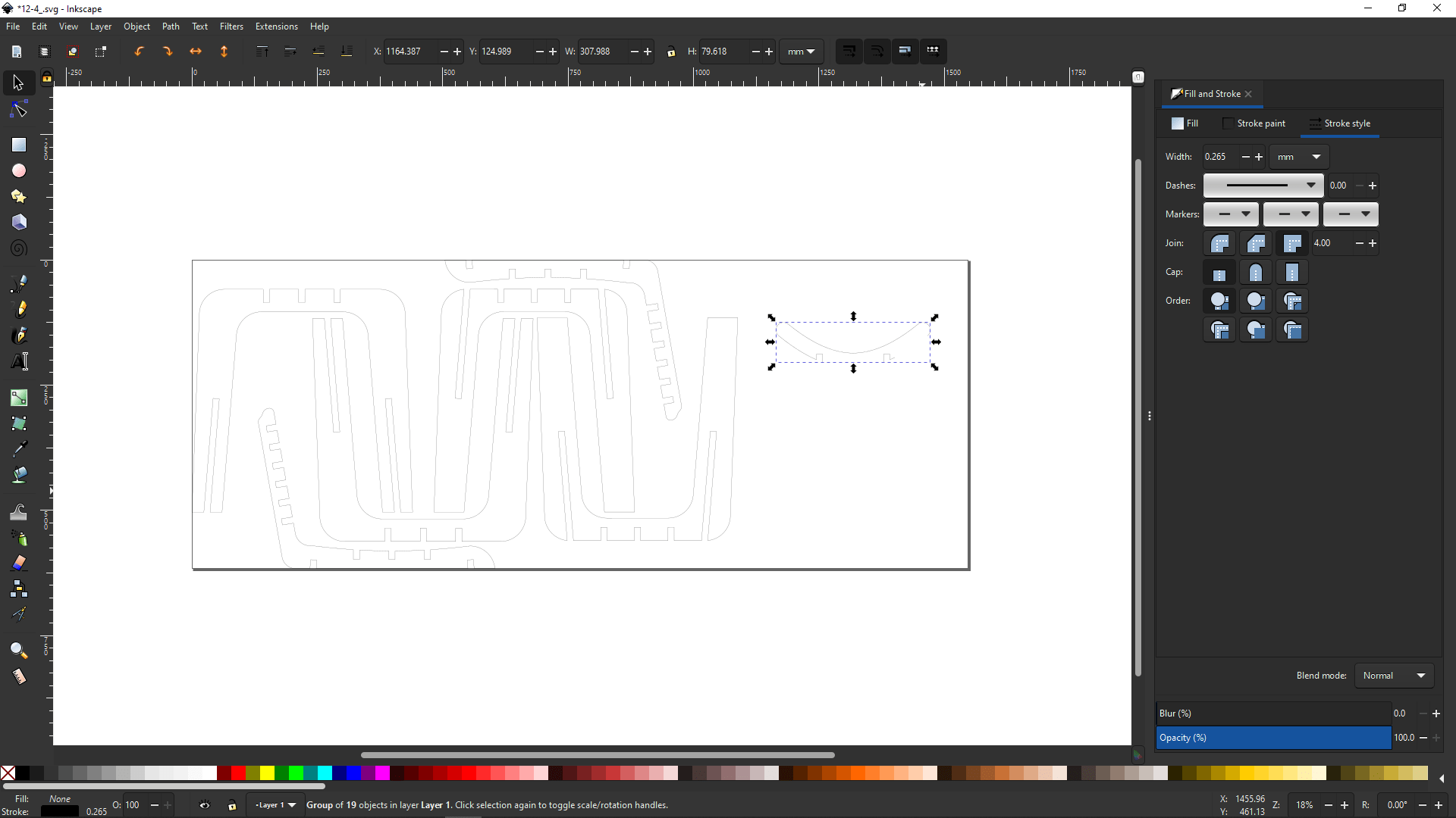
I did tried to arrange in Inkscape for laser cutting, But my curvey part not coming in Inkscape properly so by some digging on the internet I found out Inkscape may miss some curvey paths while importing from a dxf file.
I've decidede to cut rest of the part firstly and deal with the curvy ribs later. this design is in large scale or should I say meter scale so in order to scale it down from 12.4 mm thick to 3.4 for cutting in cardboard I selected and copied the height of entire object combined.
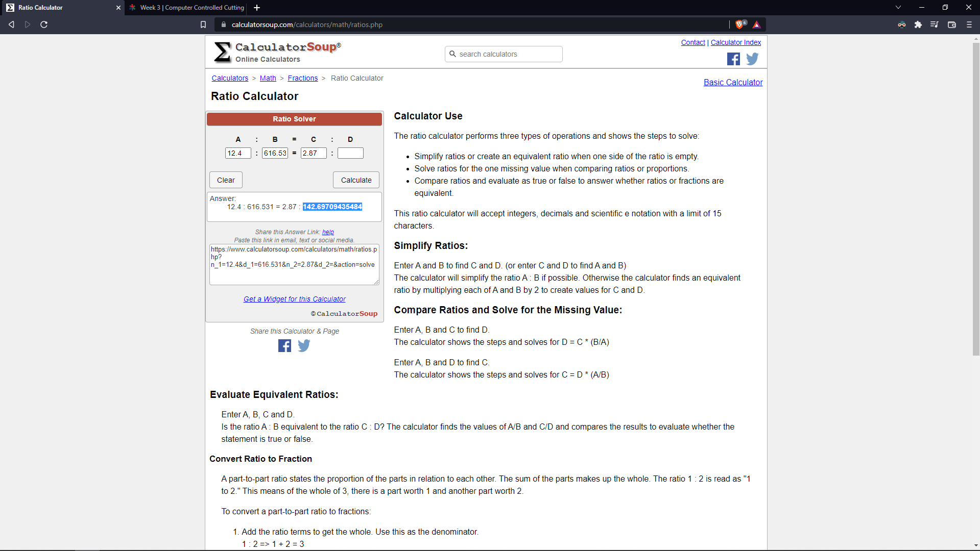
Then I opened the online Ratio calculator and entered the height and thickness one side and other side I gave target thickness to calculate which is 2.87 from our press-fit experiment during the Laser cutting week.

I copied the answer fro the ratio calculation and replaced the height of the whole document and also didn't forget to check the ratio lock icon in Inkscape.
Then I gave the red Ink to the stroke and did laser cut the parts in 3.84 mm thick cardboard for testing the design.
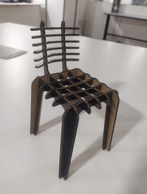
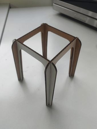
Here is the picture of the scaled down model of my design After assembled from cardboard laser cut parts.
Nesting for milling
So I designed the wooden chair in 3D but I need all components of the chair in one plane to cut on a CNC machine. I've got a 8x4 feet 12 mm play wood to make my chair and I've to arrange and cut all the components required from the sheet.This process is called nesting .
While arranging in Inkscape you can see here I was facing a DXFfile import issue problem so I decided to do the nesting in fusion 360 .
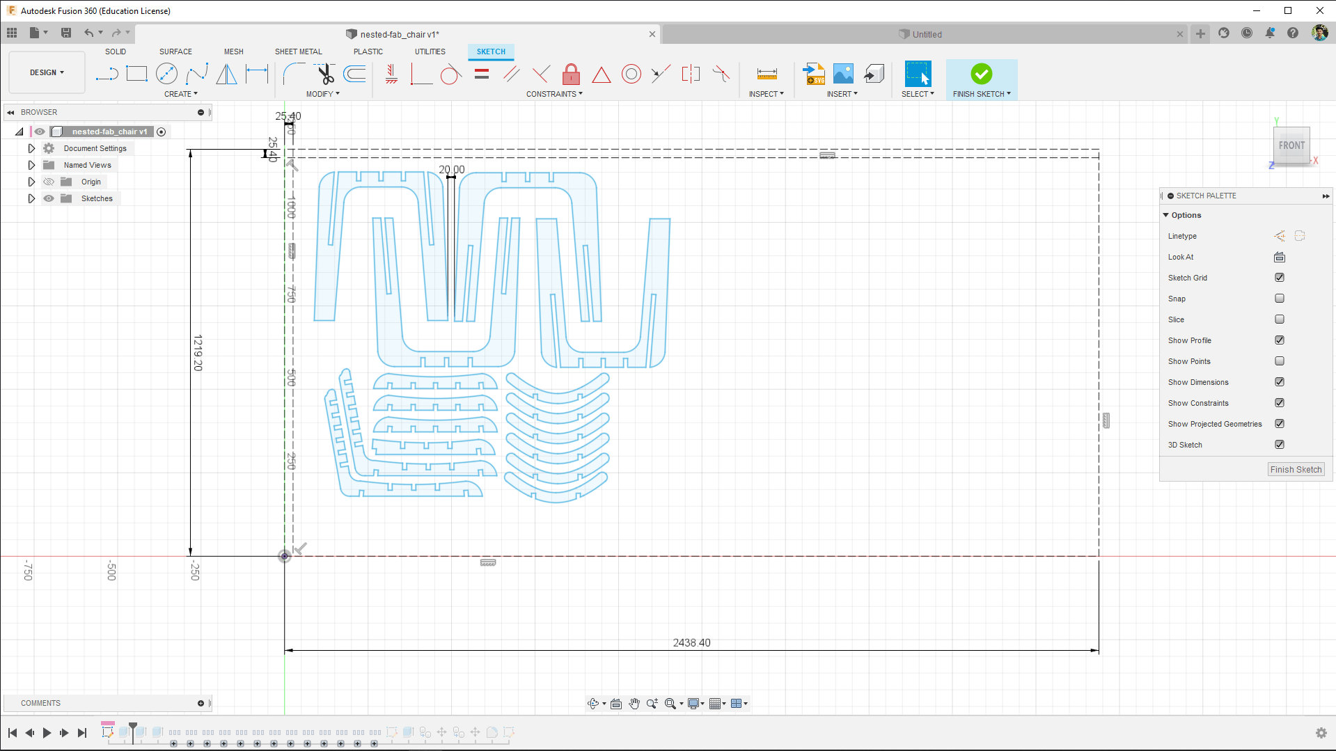
So I drew a reference box of 1219.20x2438.40 which is standard 8x4 feet Plywood sheet and then arranges all the DXF parts of my chair in it with a minimum 20 mm in between distance.
The whole components of the chair only takes just nearly half of the sheet which make my design is actually very economical.
Dog Boning
I know that needs to draw the dog bone in order to cut the part without routing edge fillets so we also learned that from group assignments that we can actually do the dog-boning process in V-carve pro while creating the tool path so I didn't draw the dog-bones in the design.
We later finds out and github page containing fusion 360 ads-in script that helps to create the dog-bone in just few information and one clicks.
The above video shows how the adds-In scrypt is working for more refer this Github page from 'tapnair'
For adding dog-bones to the surfaces, I extruded The nested file with 12.4 mm thickness to solid bodies. Then I followed the above video and documentation to add the dog bone plug-in tool in to my fusion 360 CAD software.
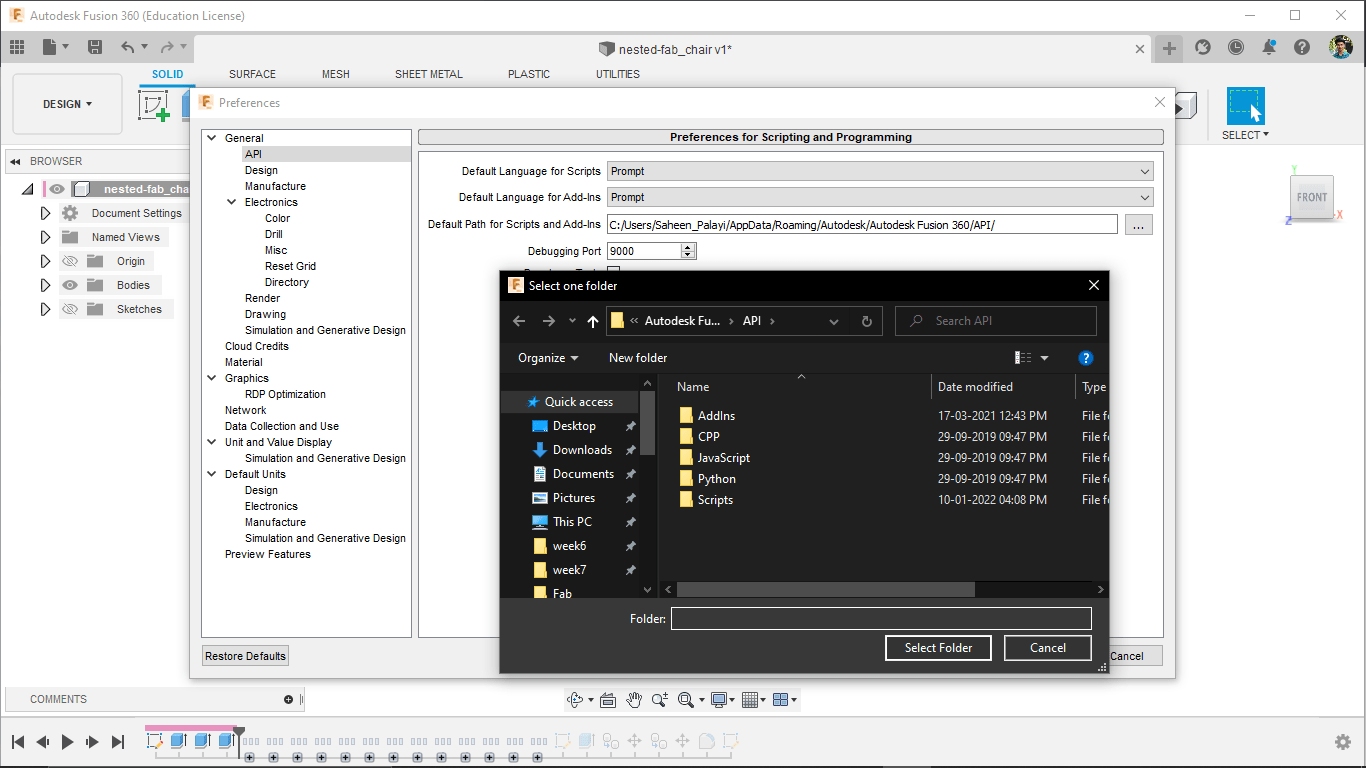
The video was made for mac users so It's better to find the 'AddIns' folder if we go to preference >> API and API folder location.
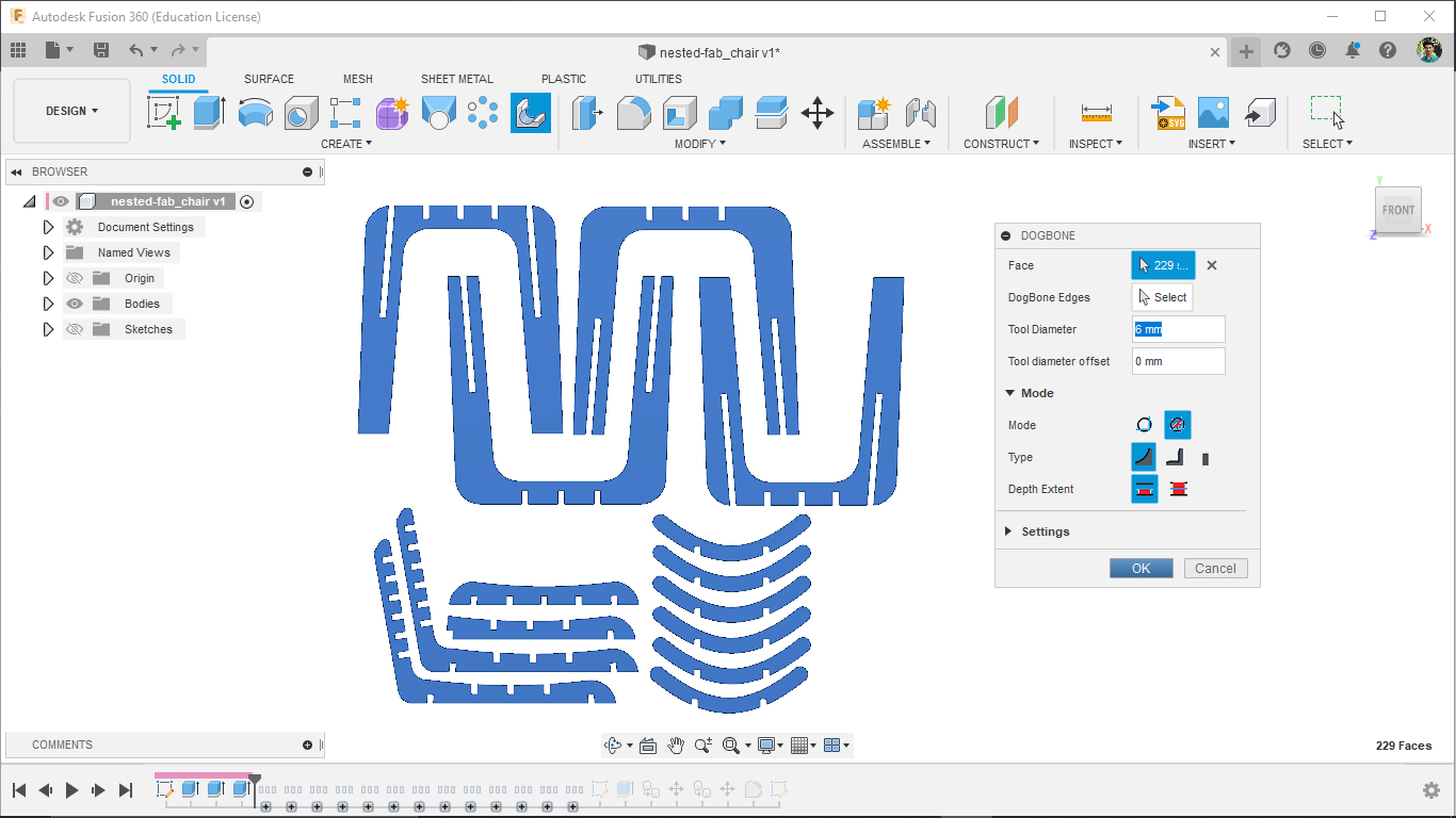
So I ran the script from addIns and runs the tool then selected all the faces to be dog bon and gave tool diameter information.
Ta Da... That was totally awesome if we zoom in we can see the dog bones are created where ever I want them.
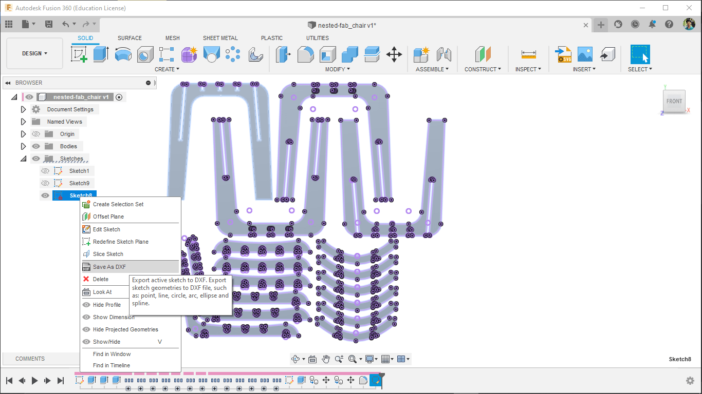
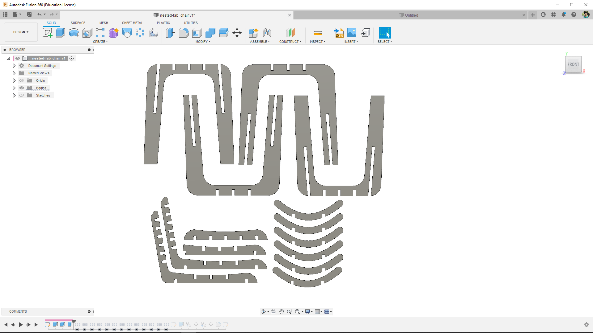
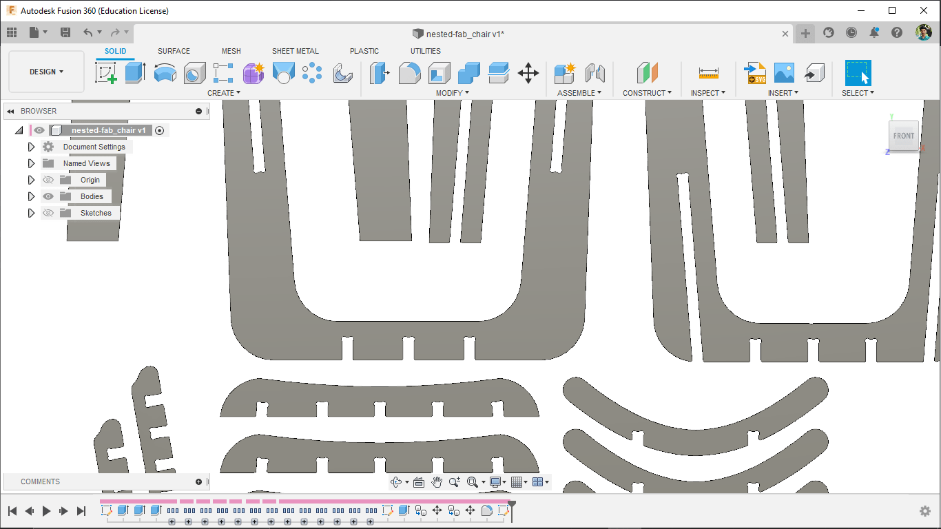
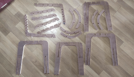
The total nesting was missing something so I added the execs components of the chair and dog boned again then I created new sketch and projected everything I wanted then exported as DXF for cutting in Shobot.
CNC Machining
Now that I completed the designing for machining, It's time to start the machining procedure just like we did during the group assignment. I have to setup-the material for cutting and make the CAM first then will do machining
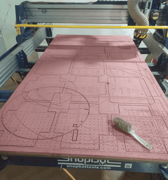
I've cleaned the bed of shopbot as a first step using vacuum cleaner and some Mob brushes. also made sure the bed is nearly flat to support the stock material pretty much flat.
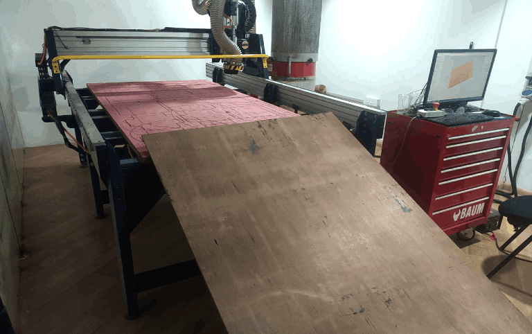
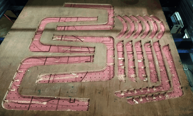
Then I loaded the 12 MM Plywood of 8x4 feet in to the bed with the help of my friends. while placing the stock material it's good to check nothing get caught in between the stock and the sacrificial material (bed)
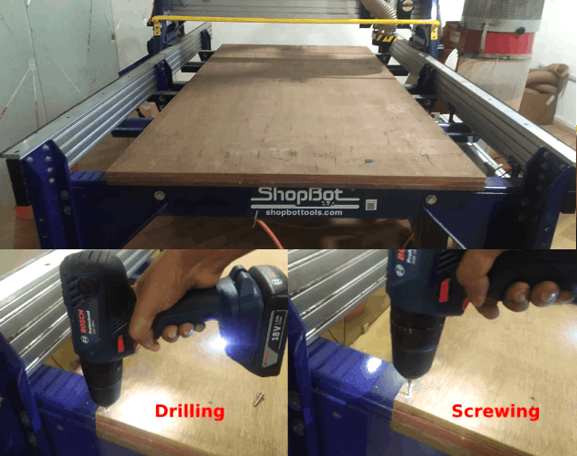
Then I aligned the stock almost parallel to the axis and started to screw down the corners of the stock using a 3/4" drywall and steel screws with the help of codeless drill. I'm also made sure the screw position not affecting the machining or no way to hit the screw while cutting the material.
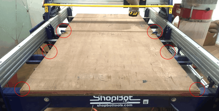
So I've screwed the stock plywood sheet in place and used two clamps at the center to hold ans avoid any vibration while cutting.The above figure shows how I did it.
Toolpath generation
Now That Secured the stock above the sacrificial layer now it's time make the tool path in V carve pro.
Setting the Origin
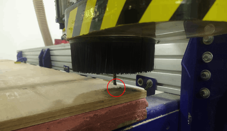
Then we sets the origin and my instructor told me that its a good idea to make a small indentation of the milling bit at the origin because if incase we got any power outages we can start again by following the mark.
References
- Fab Academy Computer-Controlled Machining classes
- ShopBot
- www.vectric.com | V- Carve Pro
- www.Opendesk.cc | CNC Machined Furnitures
- www.homestratosphere.com | The Parts of a Chair
- Online Ratio calculator
- Dogbone github Doc
Downloads
- Group Assignment Design Files
- Design Files