Week 8: Embedded Programming
In this eight week of Fab Academy, I need to program the board that I had made in previous week using different environments. Further, I need to read a microcontroller data sheet, and experiment with different architectures. In the group assignment we need to compare the performance and development workflows for different microcontroller families. Further learnings from this week are listed below:
- Document the work without fail
- Read the datasheet for the microcontroller
- Program the board you have made to do something, with as many different programming languages and programming environments as possible.
- Describe problems that I had faced, and how I fixed them
- Described the programming process/es you used
- Include hero shots of the board
The following are the softwares that I have used for learning various operations:
- Arduino IDE : Programming
- Atmel Studio 7 : Programming/Assembly
Looking back to the Electronics Production week, I found the tracing part to be difficult but I hope I could do better this time. To be honest, I initally found the embedded programming to be difficult but if you find to understand the logic behind it, it would be fun. So without further adeau we can go directly to this weeks work:
| |
|
|---|---|
| Wednesday | Prof. Neil's class on Embedded Programming |
| Thursday | Understanding datasheet of ATTiny 84, Testing Atmel Studio |
| Friday | Trying out new programs using the board |
| Saturday | Documentation, Pending ShopBot Cut |
| Sunday | Documentation |
| Monday | Review & Prepare for the machine building week |
| Tuesday | Testing Node MCU, Wi-Fi Local Server & Documentation |
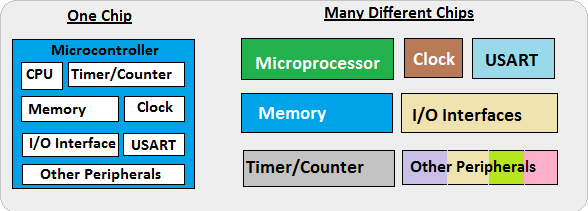
A microcontroller (or MCU for microcontroller unit) is a small computer on a single integrated circuit. In modern terminology, it is similar to, but less sophisticated than, a system on a chip or SoC; an SoC may include a microcontroller as one of its components. A microcontroller contains one or more CPUs (processor cores) along with memory and programmable input/output peripherals. Program memory in the form of ferroelectric RAM, NOR flash or OTP ROM is also often included on chip, as well as a small amount of RAM. Microcontrollers are designed for embedded applications, in contrast to the microprocessors used in personal computers or other general purpose applications consisting of various discrete chips like ADC(analog to digital converter),DAC [Digital-to-Analog Converter]
Embedded Systems
An embedded system is a controller programmed and controlled by a real-time operating system (RTOS) with a dedicated function within a larger mechanical or electrical system, often with real-time computing constraints. It is embedded as part of a complete device often including hardware and mechanical parts. Embedded systems are commonly found in consumer, industrial, automotive, medical, commercial and military applications.
AVR Microcontrollers
AVR is a family of microcontrollers developed by Atmel beginning in 1996. These are modified Harvard architecture 8-bit RISC single-chip microcontrollers. AVR was one of the first microcontroller families to use on-chip flash memory for program storage, as opposed to one-time programmable ROM, EPROM, or EEPROM used by other microcontrollers at the time. AVR microcontrollers find many applications as embedded systems; they are also used in the Arduino line of open source board designs. Here in the lab, I had used ATtiny 84 as the microcontroller for my echo hello world board. So lets dig deep into the specific board.
Microprocessor VS Microcontrollers
Microcontroller and Microprocessor both terms seem similar but there is a huge difference between these two ICs. Microprocessor only have CPU in the chip like most of the Intel Processors but Microcontroller also have RAM, ROM and other peripherals along with the CPU or processor. Both ICs have different applications and have their own advantages and disadvantages. They can be differentiated in terms of Applications, structure, internal parameters, power consumption, and cost.
ATtiny 84
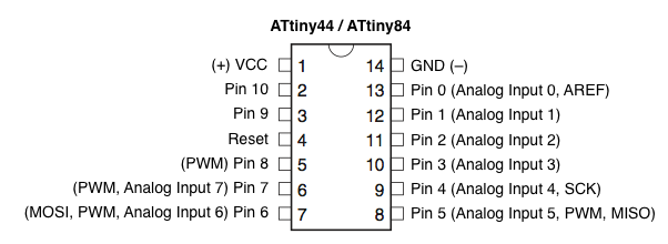
ATtiny84 is high-performance and packed with Microchip's picoPower technology in an 8-bit AVR RISC architecture based Microcontroller unit that has 14 pins, out of which 12 pins can be used as I/O pins. ATtiny84 is high-performance and packed with Microchip's picoPower technology in an 8-bit AVR RISC architecture based Microcontroller unit that has 14 pins, out of which 12 pins can be used as I/O pins. It has Powerful instruction architecture that provides a processing speed of 1 MIPS per MHz while balancing power consumption at the same time processing high-speed performance. The speed could reach up to 20 MIPS if 20 Mhz max frequency is used. ATtiny84 also comes with the debugWIRE On-Chip debugging feature, In-system Programmable SPI Port, Low-Power Idle, Power-down, and Standby Modes. It also uses a programmable brownout detection circuit as well as an On-chip Temperature Sensor. It has a wide operating voltage range from 1.8V to 5.5V. Thus it can be used in 1.8V, 3.3V, or 5.0V logic level operations. However, 0-4 Mhz operation is supported by the 1.8V input voltage for ATtiny84V. For frequency up to 10 Mhz, the minimum voltage is required 2.7V for ATtiny84, and for 20 Mhz operations, the minimum voltage is required 4.5V-5.5V. The below image is showing the detailed pin diagram of the ATtiny84.
| CPU | 8-bit AVR |
| Number of Pins | 14 |
| ADC Module | 10-bit (8-Channel) |
| External Oscillator | Yes |
| Internal Oscillator | 8 MHz |
| CPU Speed (MIPS) | 20 MIPS |
| RAM Bytes | 0.5 kB |
| Data EEPROM | 512 Bytes |
ATtiny 44
ATtiny (also known as TinyAVR) are a subfamily of the popular 8-bit AVR microcontrollers, which typically has fewer features, fewer I/O pins, and less memory than other AVR series chips. ATTINY 44 is 16 pin 8bit microcontroller.The ATtiny44 is a high-performance, low-power Microchip AVR RISC-based CMOS 8-bit microcontroller.It combines 4KB ISP flash memory, 256-Byte EEPROM, 256B SRAM, 12 general purpose I/O lines .The ATtiny44 consistof 32 general purpose working registers, an 8-bit timer/counter with two PWM channels, a 16-bit timer/counter with two PWM channels, internal and external interrupts, an 8-channel 10-bit A/D converter and a programmable gain stage (1x, 20x) for 12 differential ADC channel pairs. It has a programmable watchdog timer with internal oscillator.The a internal calibrated oscillator and three software selectable power saving modes makes it suitable for small embedded products . By executing powerful instructions in a single clock cycle the device achieves throughputs approaching 1 MIPS per MHz .It also balance power consumption and improve processing speed. The image below depicts the pin configuration ATTiny 44/84 along with the corresponding pins in the Arduino. When you program ATtiny using Arduino IDE you must specially keep an eye on the corresponding pins.
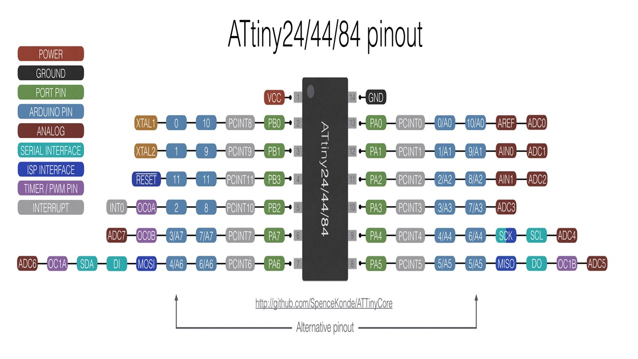
If you want to know more about the microcontroller just refer this datasheet Datasheet is the biography and manual of any electronic component. They explain exactly what a component does and how to use it. Before you start doing anything or even designing any circuit, looking at the datasheet is crucial. It holds important information like Power supply requirements, Pins Configurations and descriptions, Electrical ratings and Schematic of the IC circuit.
The following table shows the basic details of ATTiny 44
| Parameter Name | Value |
| Program Memory Type | 4 |
| CPU Speed (MIPS) | 20 |
| RAM Bytes | 256 |
| Data EEPROM (bytes) | 256 |
| Digital Communication Peripherals | 1-SPI, 1-I2C |
| Capture/Compare/PWM | 1 Input Capture, 1 CCP, 4PWM |
| Timers | 1 x 8-bit, 1 x 16-bit |
| Operating Voltage Range (V) | 1.8 to 5.5 |
| Pin Count | 14 |
Pin Descriptions
- VCC: Supply voltage
- GND: Ground
- Port A (PA7...PA0): Port A is a 8-bit bi-directional I/O port with internal pull-up resistors (selected for each bit). As inputs, Port A pins that are externally pulled low will source current if the pull-up resistors are activated
- Port B (PB3...PB0): Port B is a 4-bit bi-directional I/O port with internal pull-up resistors (selected for each bit). As inputs, Port B pins that are externally pulled low will source current if the pull-up resistors are activated.so we don't need to add a pull-up resistor externaly for button's and other purpose.
- RESET:Reset input. A low level on this pin for longer than the minimum pulse length will generate a reset, even if the clock is not running.a reset will just reset the programm that currently running
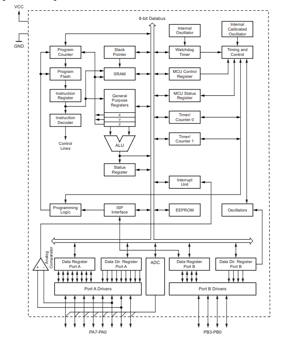
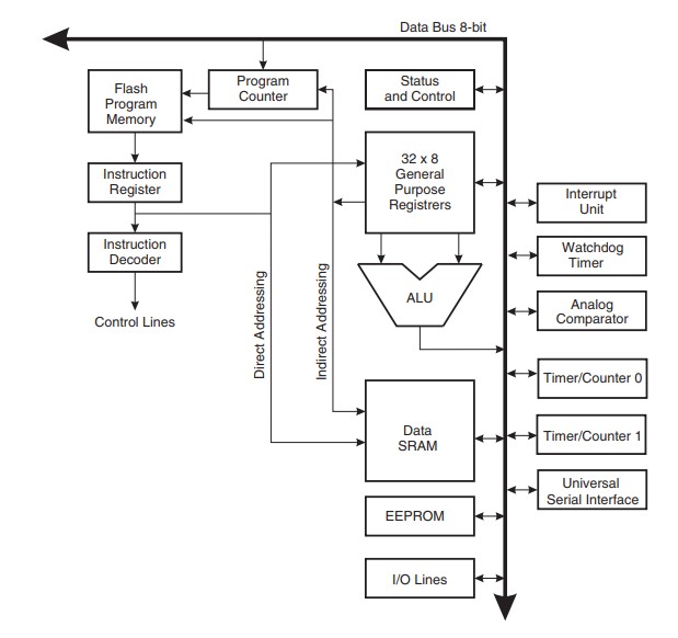
Block Diagram will explain Architecture of the Microcontroller.The AVR uses a Harvard architecture, with separate memories and buses for program and data. Instructions in the program memory are executed with a single-level pipelining. While one instruction is being executed, the next instruction is pre-fetched from the program memory. The ALU supports arithmetic and logic operations between registers or between a constant and a register. Single-register operations can also be executed in the ALU. After an arithmetic operation, the status register is updated to reflect information about the result of the operation.
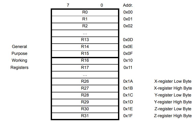
Getting to know about Registers
Registers are small memory elements in microcontrollers with 8 bits capacity. Registers can be accessed quickly by the ALU (Arithmetic and Logic Unit) of microcontrollers
Architectures Available
- Harvard architecture: The Harvard architecture is a computer architecture with physically separate storage and signal pathways for instructions and data.so it can simultaneously use both busses.
- Von Neumann architecture: The design of a von Neumann architecture machine is simpler than that of a Harvard architecture machine, which is also a stored-program system but has one dedicated set of address and data buses for reading data from and writing data to memory, and another set of address and data buses for instruction fetching.
- CISC: A complex instruction set computer processor has complex instructions that take up multiple clocks for execution. The average clock cycle per instruction (CPI) is in the range of 2 and 15.it's Performance is optimized with more focus on hardware. also It has a memory unit to implement complex instructions.CISC mainly used in Microprocessor.
- RISC: A reduced instruction set computer is a computer which only uses simple commands that can be divided into several instructions which achieve low-level operation within a single CLK cycle, as its name proposes “Reduced Instruction Set”.it's performance is optimized with more focus on software. RISC mainly Used in Microcontroller.
- PIC (Microcontroller): PIC(peripheral interface controller) is Initially this was developed for supporting PDP computers to control its peripheral devices, and therefore, named as a peripheral interface device. These microcontrollers are very fast and easy to execute a program compared with other microcontrollers. PIC Microcontroller architecture is based on Harvard architecture. PIC microcontrollers are very popular due to their ease of programming, wide availability, easy to interfacing with other peripherals, low cost, large user base and serial programming capability (reprogramming with flash memory), etc.
- AVR (Microcontroller): AVR is a family of microcontrollers developed by Atmel.These are modified Harvard architecture 8-bit RISC single-chip microcontrollers. AVR was one of the first microcontroller families to use on-chip flash memory for program storage, as opposed to one-time programmable ROM, EPROM, or EEPROM used by other microcontrollers at the time.
AVR Architecture Block Diagram
In order to maximize performance and parallelism, the AVR uses a Harvard architecture – with separate memories and buses for program and data. Instructions in the Program memory are executed with a single level pipelining. While one instruction is being executed, the next instruction is pre-fetched from the Program memory. This concept enables instructions to be executed in every clock cycle. The Program memory is In-System Reprogrammable Flash memory.
Arduino is an open source computer hardware and software company, project, and user community that designs and manufactures single-board microcontrollers and microcontroller kits for building digital devices and interactive objects that can sense and control objects in the physical and digital world. Since I have an exposure to Arduino IDE during my undergraduate studies, I found this compartively easier. To start with, the IDE doesn't Support ATTiny 84/44 so the first step is to add the board directories to the Arduino environment. The steps to add the directory is as follows:
ATTiny 44/84 to Arduino Pin Map
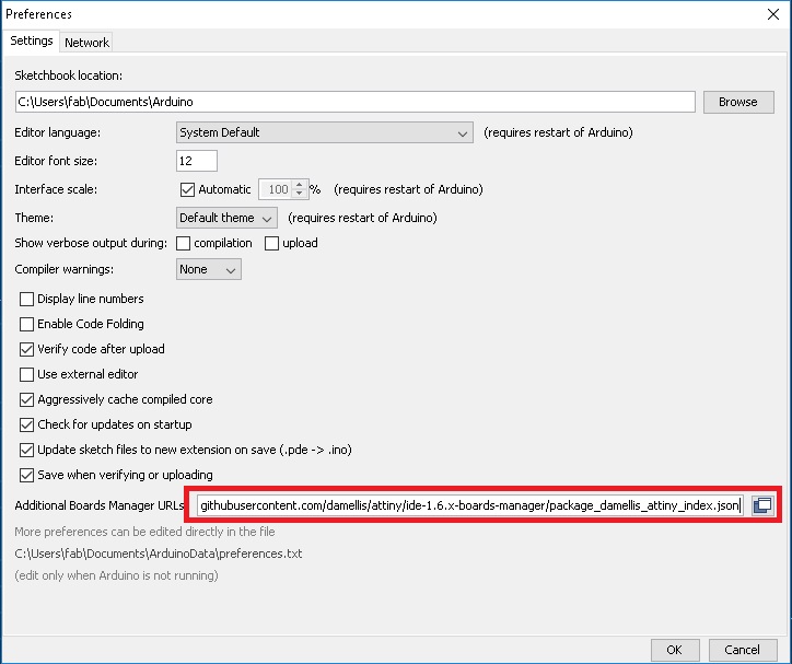
Go to File -> Preferances. Then look for the space to add additional board manager URL. Once you get there, add the URL mentioned below and click "OK"
https://raw.githubusercontent.com/damellis/attiny/ide-1.6.x-boards-manager/package_damellis_attiny_index.json
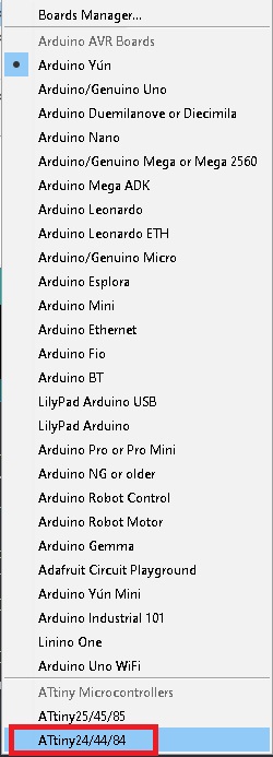
Now to setup the ATtiny board go to Tools -> Boards and click Board Manager
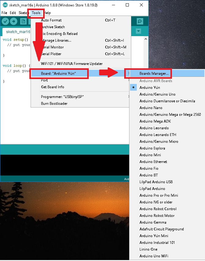
The next step is to search for ATtiny in Board Manager.
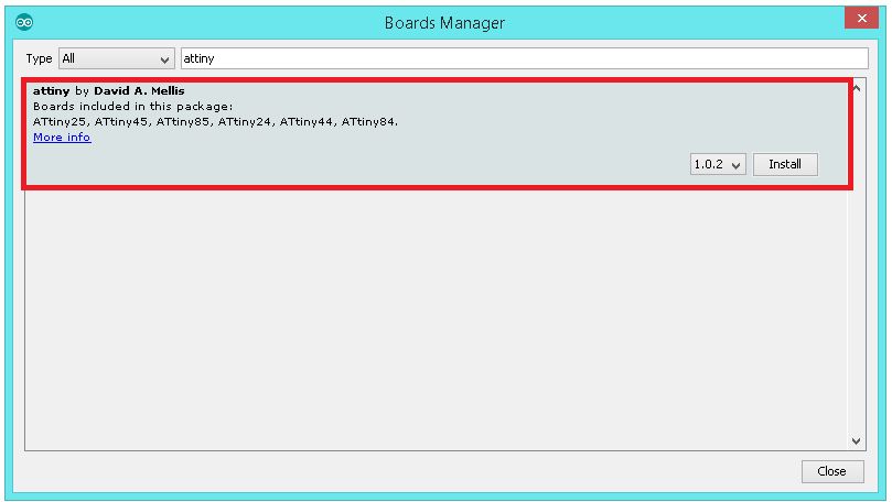
Now if you look at the Board Manager then ATtiny pops up.
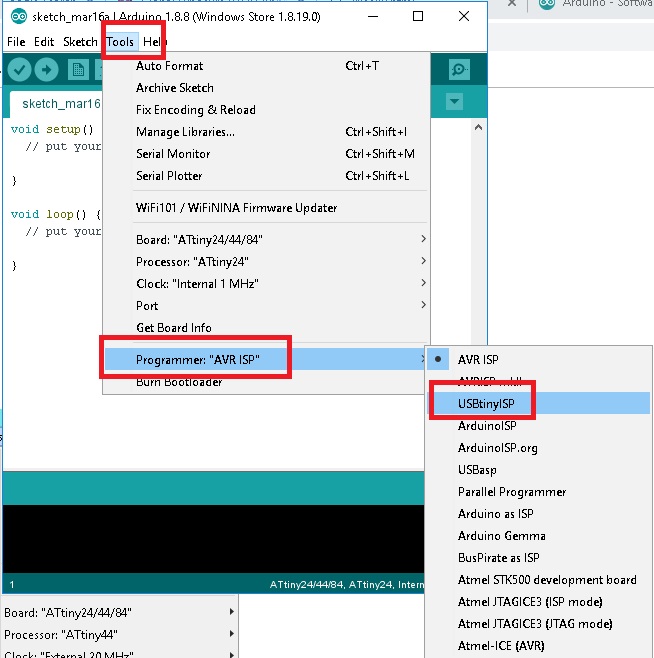
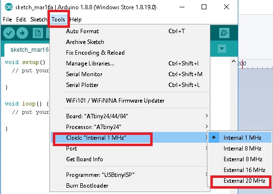
This is an important step, now make sure that the Programmer is selected as USBTinyISP and also verify that the clock speed is selected as 20MHz under Tool section. Do upload the Bootloader bu selecting Burn Bootloader in Tools
Arduino Code: LED Blink
void setup() {

    pinMode(8, OUTPUT);
  }

  // the loop function runs over and over again forever
  void loop() {
    digitalWrite(8, HIGH);   // turn the LED on (HIGH is the voltage level)
    delay(1000);                       // wait for a second
    digitalWrite(8, LOW);    // turn the LED off by making the voltage LOW
    delay(1000);                       // wait for a second
  }
Arduino Code: LED with Push Button
    // constants won't change. They're used here to set pin numbers:
    const int buttonPin = 7;     // the number of the pushbutton pin
    const int ledPin =  8;      // the number of the LED pin

    // variables will change:
    int buttonState = 0;         // variable for reading the pushbutton status

    void setup() {
      // initialize the LED pin as an output:
      pinMode(ledPin, OUTPUT);
      // initialize the pushbutton pin as an input:
      pinMode(buttonPin, INPUT_PULLUP);
    }

    void loop() {
      // read the state of the pushbutton value:
      buttonState = digitalRead(buttonPin);

      // check if the pushbutton is pressed. If it is, the buttonState is HIGH:
        if (buttonState == LOW) {
          // turn LED on:
          digitalWrite(ledPin, HIGH);
        } else {
        // turn LED off:
        digitalWrite(ledPin, LOW);
      }
    }
Arduino Code: LED Fade
    int led = 8;           // the PWM pin the LED is attached to
    int brightness = 0;    // how bright the LED is
    int fadeAmount = 5;    // how many points to fade the LED by

    // the setup routine runs once when you press reset:
    void setup() {
      // declare pin 8 (PB2) to be an output:
      pinMode(led, OUTPUT);
    }

    // the loop routine runs over and over again forever:
    void loop() {
      // set the brightness of pin 8:
      analogWrite(led, brightness);

      // change the brightness for next time through the loop:
      brightness = brightness + fadeAmount;

      // reverse the direction of the fading at the ends of the fade:
      if (brightness <= 0 || brightness >= 255) {
        fadeAmount = -fadeAmount;
      }
      // wait for 30 milliseconds to see the dimming effect
      delay(30);
    }
Arduino Code: Push button with different functions
For a change, I tried to test an interesting program. The logic is that when I press the button for first time the led blinks, the second push make the led to fade.
        const int buttonPin = 7;     // the number of the pushbutton pin
        const int ledPin =  8;      // the number of the LED pin
        int led = 8;           // the PWM pin the LED is attached to
        int brightness = 0;    // how bright the LED is
        int fadeAmount = 3;    // how many points to fade the LED by
         int k=0;

        void setup() {
           pinMode(8, OUTPUT);

         // initialize the LED pin as an output:
          pinMode(ledPin, OUTPUT);
          // initialize the pushbutton pin as an input:
          pinMode(buttonPin, INPUT_PULLUP);

        }

        void loop() {


         if (digitalRead(buttonPin) == LOW) {
          if(k==2){
            k=0;
            }

          else{
            k=k+1;
          }
          }

         switch (k) {

          case 1: //fade
        {
          // set the brightness of pin 9:
          analogWrite(led, brightness);

          // change the brightness for next time through the loop:
          brightness = brightness + fadeAmount;

          // reverse the direction of the fading at the ends of the fade:
          if (brightness <= 0 || brightness >= 255) {
            fadeAmount = -fadeAmount;
          }
          // wait for 30 milliseconds to see the dimming effect
          delay(30);

        }

        break;
        case 2: //blink
        {
            digitalWrite(8, HIGH);   // turn the LED on (HIGH is the voltage level)
          delay(100);                       // wait for a second
          digitalWrite(8, LOW);    // turn the LED off by making the voltage LOW
          delay(100);                       // wait for a second

        }

        break;
        default: break;

         }

        }
Studio 7 is the integrated development platform (IDP) for developing and debugging all AVR® and SAM microcontroller applications. The Atmel Studio 7 IDP gives you a seamless and easy-to-use environment to write, build and debug your applications written in C/C++ or assembly code. It also connects seamlessly to the debuggers, programmers and development kits that support AVR® and SAM devices. The Atmel Studio 7 IDP gives you a seamless and easy-to-use environment to write, build and debug your applications written in C/C++ or assembly code. It also connects seamlessly to the debuggers, programmers and development kits that support AVR® and SAM devices. Additionally, Studio includes Atmel Gallery, an online app store that allows you to extend your development environment with plug-ins developed by Microchip as well as third-party tool and embedded software vendors. Studio 7 can also seamlessly import your Arduino sketches as C++ projects, providing a simple transition path from Makerspace to Marketplace. In Atmel Studio we are writing C code. In order to use the Atmel Studio with our Fab ISP we need to configure the studio before use. In embedded c we need handle the registers.Each of the AVR Digital I/O ports is associated with three (3) I/O register. A Data Direction Register (DDRx), A Pin Register (PINx) and a Port Register (PORTx). Where x is the port A, B, C, etc.
DDRx - Port X Data Direction Register
DDRx is an 8-bit register which stores configuration information for the pins of Portx. Writing a 1 in the pin location in the DDRx makes the physical pin of that port an output pin and writing a 0 makes that pin an input pin.
PINx - Port X Input Pins Register
PINx is an 8-bit register that stores the logic value, the current state, of the physical pins on Portx. So to read the values on the pins of Portx, you read the values that are in its PIN register.
PORTx - Port X Data Register
PORTx is an 8-bit register which stores the logic values that currently being outputted on the physical pins of Portx if the pins are configured as output pins. So to write values to a port, you write the values to the PORT register of that port.
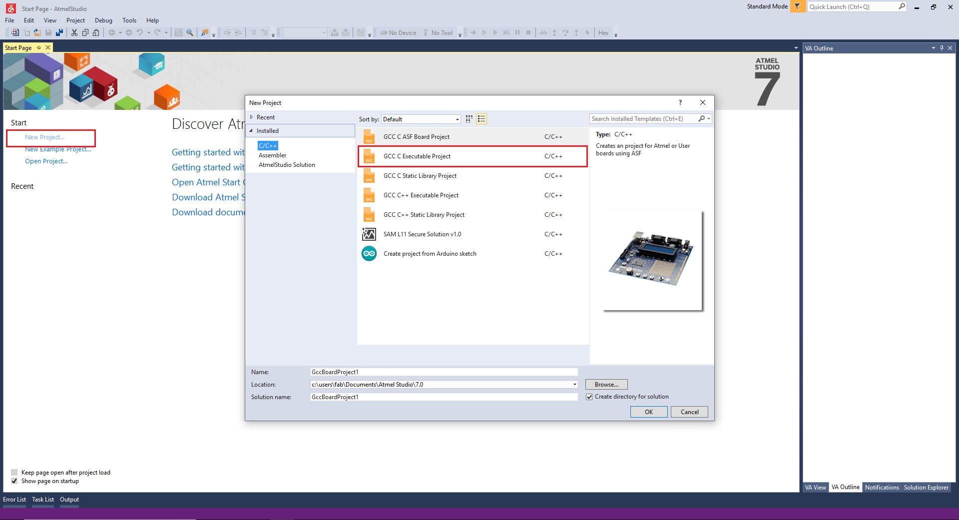
For programming first install and open Atmel Studio 7. Click "New Project" and select "GCC C Executable project". Click ok to confirm the selection.
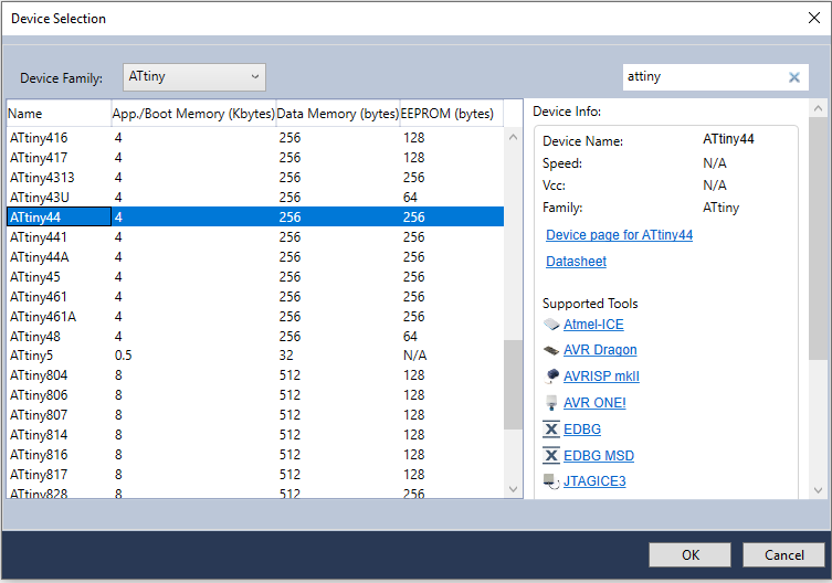
Now you need to select the board depending on which you have. I had selected ATtiny 84/44 and click OK to confirm the operation. Now a new environment has been created.
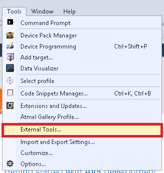
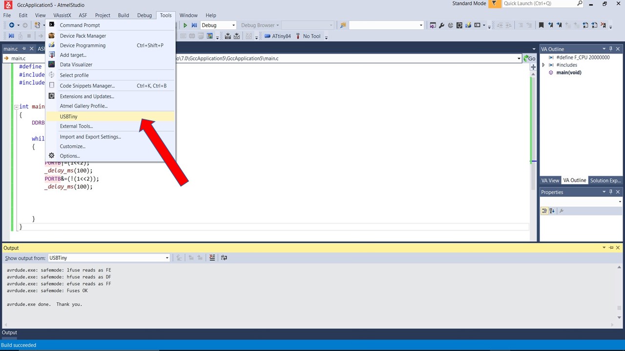
Now we need to setup some parameters for USBTiny debugging. For that Go to "Tools" and Select "External Tools."
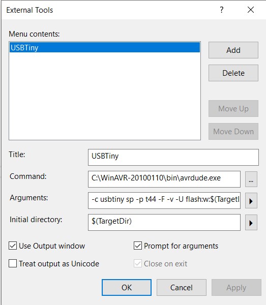
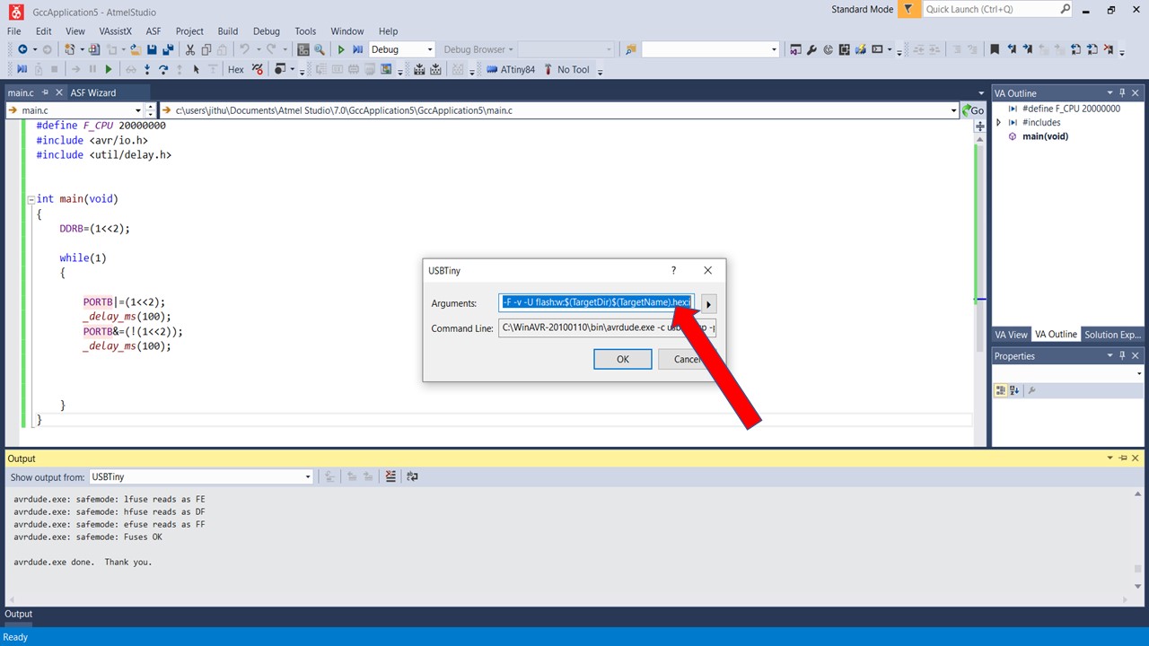
The next step is to add the programmer to the environment. For that you need to select Tools -> External Tools and in the space fill the following command. Then apply and save the tools
-c usbtiny sp -p t44 -F -v -U flash:w:$(TargetDir)$(TargetName).hex:i
- Title:- USBTiny ISP Debug
- Command :- avrdude.exe
- Arguments :- -c usbtiny -p attiny44 -U flash:w:$(ProjectDir)Debug\$(TargetName).hex:i
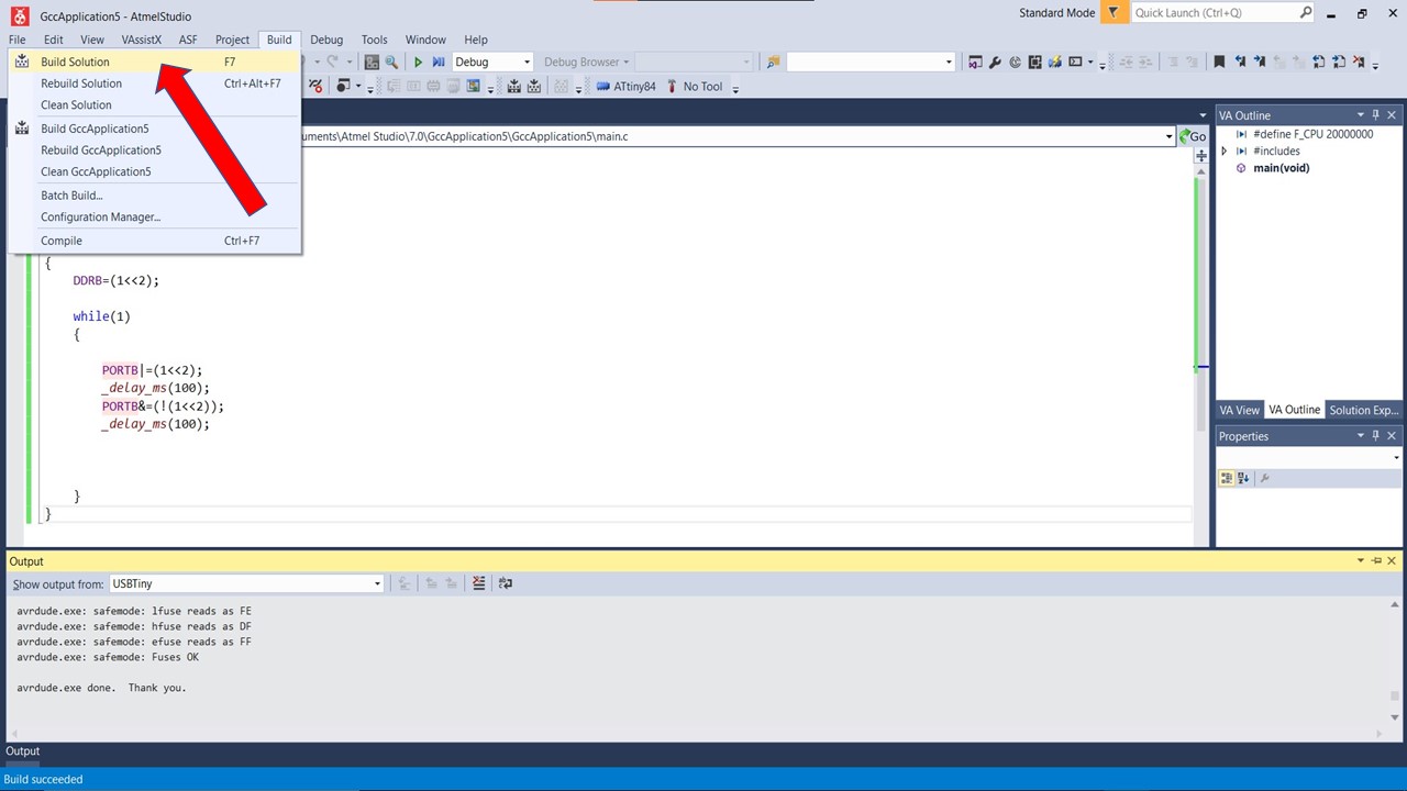
Now for testing the board, Open "Build" from the menu and click "Build solution"
Once compiled, you need to upload to the board. For that go to Tools -> USBTiny
Finally click OK to flash the file.
So I had tried out a program similar to one done in Arduino IDE to blink the led using C commands.
Atmel Studio: Blink Code
    #define F_CPU 20000000
    #include < avr/io.h >
    #include < util/delay.h >


    int main(void)
    {
        DDRB=(1 << 2);

        while(1)
        {

            PORTB|=(1 << 2);
            _delay_ms(100);
            PORTB&=(!(1 << 2));
            _delay_ms(100);


        }
    }
Here is another code of led turning on while pressing the push button.
    #include < avr/io.h >                    // AVR input/output library

    #define F_CPU 20000000                 // Since we connected a 20MHz crystal into the circuit

    #include < util/delay.h >                // Delay library

    int main(void)
    {

        DDRB |= (1 << 2 ); //LED
        DDRA &=~(1<< 7); //SWITCH
        PORTA |= (1<< 7);
        PORTB &=~(1<< 2);
    }
    while(1)
    {

        if (!(PINA & (1 << 7 )))
        {
            PORTB = PORTB|(1 << 2 ); //HIGH

        }
        else
        {  PORTB &=~(1 << 2); //LOW

        }

    }
Assembly language is an alphanumeric representation of machine code.The instructions used in writing programs in assembly language are not general but specific to the microcontroller. Each company provides a set of instructions for there microcontrollers. Inorder to program in assembly language you must refer ATtiny 84/44 Datasheet.
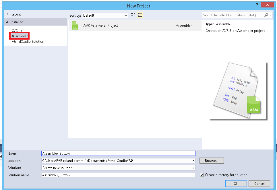
When we code in Assembler we need the datasheet to know about the MC instruction set. So here we are using Atmel studio to write the Assebler code .First we need to start a project that we did in the C code.After that Select the Assembler in template and Click ok. After that Select our Target Microcontroller , we have ATtiny84.
    .org 0
    sbi DDRB,2 //LED - PB2
    cbi DDRA,7 // SWITCH - PA7
    SBI PORTA,7 //SETTING THE SWITCH PIN TO HIGH (PULLUP)

   main:
   SBIC PINA,7 //CHECK THE STATE OF THE SWITCH - SKIP IF 0 (CLEAR)
    Cbi PORTB,2 // TURN LED OFF
   SBIC PINA,7 //CHECK THE STATE OF THE SWITCH - SKIP IF 0 (CLEAR)
    RJMP main // JUMP TO MAIN IF STATE CLEARED
    Sbi PORTB,2 //TURN ON THE LED

    RJMP main //JUMP TO MAIL CREATING THE LOOP
This our Assembler code that will Turn on the led when we press the LED.
.orgit used for set the PC(Programme Counter) in a Specific value, in here we set PC in Zerosbiit is used to set the pin to OUTPUT (ie 2nd bit of B as 1)cbiClear the bit usually used for input (7th pin of A as 0)mainthis is a label name it's like a function, all the code under the label we can get by calling the label nameSBICin here it will skips the next instruction depending on the I/O bit's stateRJMPRelative Jump , here it will jump into a specfic label's that we mentioned , so here it will jump to main label.
For Uploading code first we need to build/compile it by using Build -> Build Solution and compile it by selecting ATtiny 84 and enjoy the magic. since the output is same as expected I am not adding the video again.
Console
    ----------- Build started: Project: AssemblerApplication3, Configuration: Debug AVR ------
    Build started.
    Project "AssemblerApplication3.asmproj" (default targets):
    Target "PreBuildEvent" skipped, due to false condition; ('$(PreBuildEvent)'!='') was evaluated as (''!='').
    Target "CoreBuild" in file "C:\Program Files (x86)\Atmel\Studio\7.0\Vs\Assembler.targets" from project "c:\users\jithu\Documents\Atmel Studio\7.0\AssemblerApplication3\AssemblerApplication3\AssemblerApplication3.asmproj" (target "Build" depends on it):
      Task "RunAssemblerTask"
        C:\Program Files (x86)\Atmel\Studio\7.0\toolchain\avr8\avrassembler\avrasm2.exe -fI -o "AssemblerApplication3.hex"  -m "AssemblerApplication3.map"  -l "AssemblerApplication3.lss"  -S "AssemblerApplication3.tmp"  -W+ie -I"C:/Program Files (x86)\Atmel\Studio\7.0\Packs\atmel\ATtiny_DFP\1.1.102\avrasm\inc"  -itn84def.inc -d "c:\users\jithu\Documents\Atmel Studio\7.0\AssemblerApplication3\AssemblerApplication3\Debug\AssemblerApplication3.obj"  "c:\users\jithu\Documents\Atmel Studio\7.0\AssemblerApplication3\AssemblerApplication3\main.asm"  -I "C:\Program Files (x86)\Atmel\Studio\7.0\toolchain\avr8\avrassembler\Include"
        AVRASM: AVR macro assembler 2.2.6 (build 63 Apr 26 2016 14:42:08)
        Copyright (C) 1995-2016 ATMEL Corporation
        [builtin](2): Including file 'C:/Program Files (x86)\Atmel\Studio\7.0\Packs\atmel\ATtiny_DFP\1.1.102\avrasm\inc\tn84def.inc'
        [builtin](2): Including file 'C:/Program Files (x86)\Atmel\Studio\7.0\Packs\atmel\ATtiny_DFP\1.1.102\avrasm\inc\tn84def.inc'
        "ATtiny84" memory use summary [bytes]:
        Segment   Begin    End      Code   Data   Used    Size   Use%
        ---------------------------------------------------------------
        [.cseg] 0x000000 0x000012     18      0     18    8192   0.2%
        [.dseg] 0x000060 0x000060      0      0      0     512   0.0%
        [.eseg] 0x000000 0x000000      0      0      0     512   0.0%
        Assembly complete, 0 errors. 0 warnings
      Done executing task "RunAssemblerTask".
    Done building target "CoreBuild" in project "AssemblerApplication3.asmproj".
    Target "PostBuildEvent" skipped, due to false condition; ('$(PostBuildEvent)' != '') was evaluated as ('' != '').
    Target "Build" in file "C:\Program Files (x86)\Atmel\Studio\7.0\Vs\Avr.common.targets" from project "c:\users\jithu\Documents\Atmel Studio\7.0\AssemblerApplication3\AssemblerApplication3\AssemblerApplication3.asmproj" (entry point):
    Done building target "Build" in project "AssemblerApplication3.asmproj".
    Done building project "AssemblerApplication3.asmproj".

    Build succeeded.
    ========== Build: 1 succeeded or up-to-date, 0 failed, 0 skipped ==========
Console Output: Flashing
    avrdude.exe: Version 5.10, compiled on Jan 19 2010 at 10:45:23
    Copyright (c) 2000-2005 Brian Dean, http://www.bdmicro.com/
    Copyright (c) 2007-2009 Joerg Wunsch

    System wide configuration file is "C:\WinAVR-20100110\bin\avrdude.conf"

    Using Port                    : lpt1
    Using Programmer              : usbtiny
    AVR Part                      : ATtiny44
    Chip Erase delay              : 4500 us
    PAGEL                         : P00
    BS2                           : P00
    RESET disposition             : possible i/o
    RETRY pulse                   : SCK
    serial program mode           : yes
    parallel program mode         : yes
    Timeout                       : 200
    StabDelay                     : 100
    CmdexeDelay                   : 25
    SyncLoops                     : 32
    ByteDelay                     : 0
    PollIndex                     : 3
    PollValue                     : 0x53
    Memory Detail                 :

                             Block Poll               Page                       Polled
      Memory Type Mode Delay Size  Indx Paged  Size   Size #Pages MinW  MaxW   ReadBack
      ----------- ---- ----- ----- ---- ------ ------ ---- ------ ----- ----- ---------
      eeprom        65     6     4    0 no        256    4      0  4000  4500 0xff 0xff
      flash         65     6    32    0 yes      4096   64     64  4500  4500 0xff 0xff
      signature      0     0     0    0 no          3    0      0     0     0 0x00 0x00
      lock           0     0     0    0 no          1    0      0  9000  9000 0x00 0x00
      lfuse          0     0     0    0 no          1    0      0  9000  9000 0x00 0x00
      hfuse          0     0     0    0 no          1    0      0  9000  9000 0x00 0x00
      efuse          0     0     0    0 no          1    0      0  9000  9000 0x00 0x00
      calibration    0     0     0    0 no          1    0      0     0     0 0x00 0x00

    Programmer Type : USBtiny
    Description     : USBtiny simple USB programmer, http://www.ladyada.net/make/usbtinyisp/
avrdude.exe: programmer operation not supported

avrdude.exe: Using SCK period of 10 usec
avrdude.exe: AVR device initialized and ready to accept instructions

Reading | ################################################## | 100% 0.00s

avrdude.exe: Device signature = 0x1e930c
avrdude.exe: Expected signature for ATtiny44 is 1E 92 07
avrdude.exe: safemode: lfuse reads as FE
avrdude.exe: safemode: hfuse reads as DF
avrdude.exe: safemode: efuse reads as FF
avrdude.exe: NOTE: FLASH memory has been specified, an erase cycle will be performed
    To disable this feature, specify the -D option.
avrdude.exe: erasing chip
avrdude.exe: Using SCK period of 10 usec
avrdude.exe: reading input file "c:\users\jithu\Documents\Atmel Studio\7.0\AssemblerApplication3\AssemblerApplication3\Debug\AssemblerApplication3.hex"
avrdude.exe: writing flash (18 bytes):

Writing | ################################################## | 100% 0.02s

avrdude.exe: 18 bytes of flash written
avrdude.exe: verifying flash memory against c:\users\jithu\Documents\Atmel Studio\7.0\AssemblerApplication3\AssemblerApplication3\Debug\AssemblerApplication3.hex:
avrdude.exe: load data flash data from input file c:\users\jithu\Documents\Atmel Studio\7.0\AssemblerApplication3\AssemblerApplication3\Debug\AssemblerApplication3.hex:
avrdude.exe: input file c:\users\jithu\Documents\Atmel Studio\7.0\AssemblerApplication3\AssemblerApplication3\Debug\AssemblerApplication3.hex contains 18 bytes
avrdude.exe: reading on-chip flash data:

Reading | ################################################## | 100% 0.02s

avrdude.exe: verifying ...
avrdude.exe: 18 bytes of flash verified

avrdude.exe: safemode: lfuse reads as FE
avrdude.exe: safemode: hfuse reads as DF
avrdude.exe: safemode: efuse reads as FF
avrdude.exe: safemode: Fuses OK

avrdude.exe done.  Thank you.
Checking Blink LED using Arduino and DSO
For fun, I and my classmate Saheen tried to find the waveform produced by the blink program with a delay time of 10ms. The output was interesting and I will add the video of it below:
In this week group assignment is to try out some other architecture other than AVR microcontrollers. For the comparison we had used the following Boards
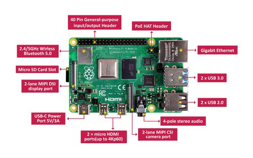
- Raspberry Pi 4: ARM Architecture
- NodeMCU ESP8266: Harvard Architecture
- NodeMCU ESP32S: Harvard Architecture
- Nucleo STM32F401: ARM Architecture
- Lattice Ice Stick: FGPA
Raspberry Pi
ARM, previously Advanced RISC Machine, originally Acorn RISC Machine, is a family of reduced instruction set computing (RISC) architectures for computer processors, configured for various environments.Processors that have a RISC architecture typically require fewer transistors than those with a complex instruction set computing (CISC) architecture (such as the x86 processors found in most personal computers), which improves cost, power consumption, and heat dissipation. These characteristics are desirable for light, portable, battery-powered device-including smartphones, laptops and tablet computers, and other embedded systems.] For supercomputers, which consume large amounts of electricity, ARM could also be a power-efficient solution. Most of our mobile phones are based on ARM and now it used on server's and super controllers.Raspberry Pi is Single board computer that based on ARM.
For more details check my friend Abel's webpage here
Nucleo STM32F401
STM32 is a family of 32-bit microcontroller integrated circuits by STMicroelectronics. The STM32 chips are grouped into related series that are based around the same 32-bit ARM processor core, such as the Cortex-M7F, Cortex-M4F, Cortex-M3, Cortex-M0+, or Cortex-M0. Internally, each microcontroller consists of the processor core, static RAM memory, flash memory, debugging interface, and various peripherals. In here Fablab Kochi we have the STM32F401 series Nucleo development boards.it's a part of the STM32 Dynamic Efficiency™ device range. These devices offer the best balance of dynamic power consumption (in run mode) and processing performance, while integrating a high number of added-value features in packages as small as 3 x 3 mm. The MCUs deliver the performance of Cortex®-M4 core with floating point unit, running at 84 MHz, while achieving outstandingly low power consumption values in run and stop modes. STM32 has more pin functions, flash memory and features compared to other boards available and it also a 32-bit microcontroller. It is cheap and functional board to work on compared to all other boards we had tested.
For more details visit my friend Saheen's website here
Lattice ICEstick Evaluation Board 40HX1K
This was the board which allows to set it to any architectures. This is called FPGA board meaning Field Programmable Gate Array. Field Programmable Gate Arrays (FPGAs) are semiconductor devices that are based around a matrix of configurable logic blocks (CLBs) connected via programmable interconnects. FPGAs can be reprogrammed to desired application or functionality requirements after manufacturing.
ICEstick Evaluation Board features the following on-board components:
- High-performance, low-power iCE40HX1K FPGA
- FTDI 2232H USB device allows iCE device programming and UART interface to a PC
- Vishay TFDU4101 IrDA transceiver
- 2 x 6 position Diligent PmodTM compatible connector enables many other peripheral connections
- Discera 12Mhz MEMS oscillator
- Micron 32Mbit N25Q32 SPI flash
- 16 LVCMOS/LVTTL (3.3V) digital I/O connections on 0.1†through-hole connections
- USB connector provides the power supply
The beauty of this board is that we can arange this board in such any way we can. We can test any schematic and architecture in this board. This is a perfect device in which you can use to prototype the PCB and controllers. It contains array or electronic components which is connected according to your input and requirement without hassle of making newboard. You need two softwares to run it. First to arrange the array of the electronic components according to your requirement. We can use "iCEcube-2" to perform this operation. Then we can use other embedded programing language to flash the board.
For more details visit my friend Pallab's page here
NodeMCU ESP32S
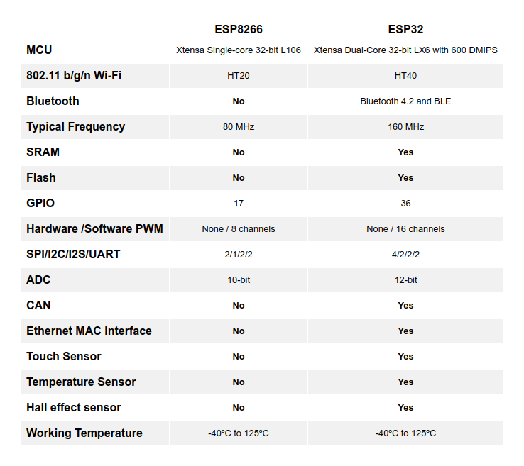
The NodeMCU ESP-32S is one of the development board created by NodeMcu to evaluate the ESP-WROOM-32 module. It is based on the ESP32 microcontroller that boasts Wifi, Bluetooth, Ethernet and Low Power support all in a single chip. The link to the NodeMCY ESP32S is given here. There are essentially three ways to build your NodeMCU firmware: cloud build service, Docker image, dedicated Linux environment (possibly VM). The Node MCU ESP32S can be programmed using Arduino IDE. You can also use Micropython Online, it has a terminal, editor, circuit. Now comparing Node MCU ESP32S with tested ESP8266
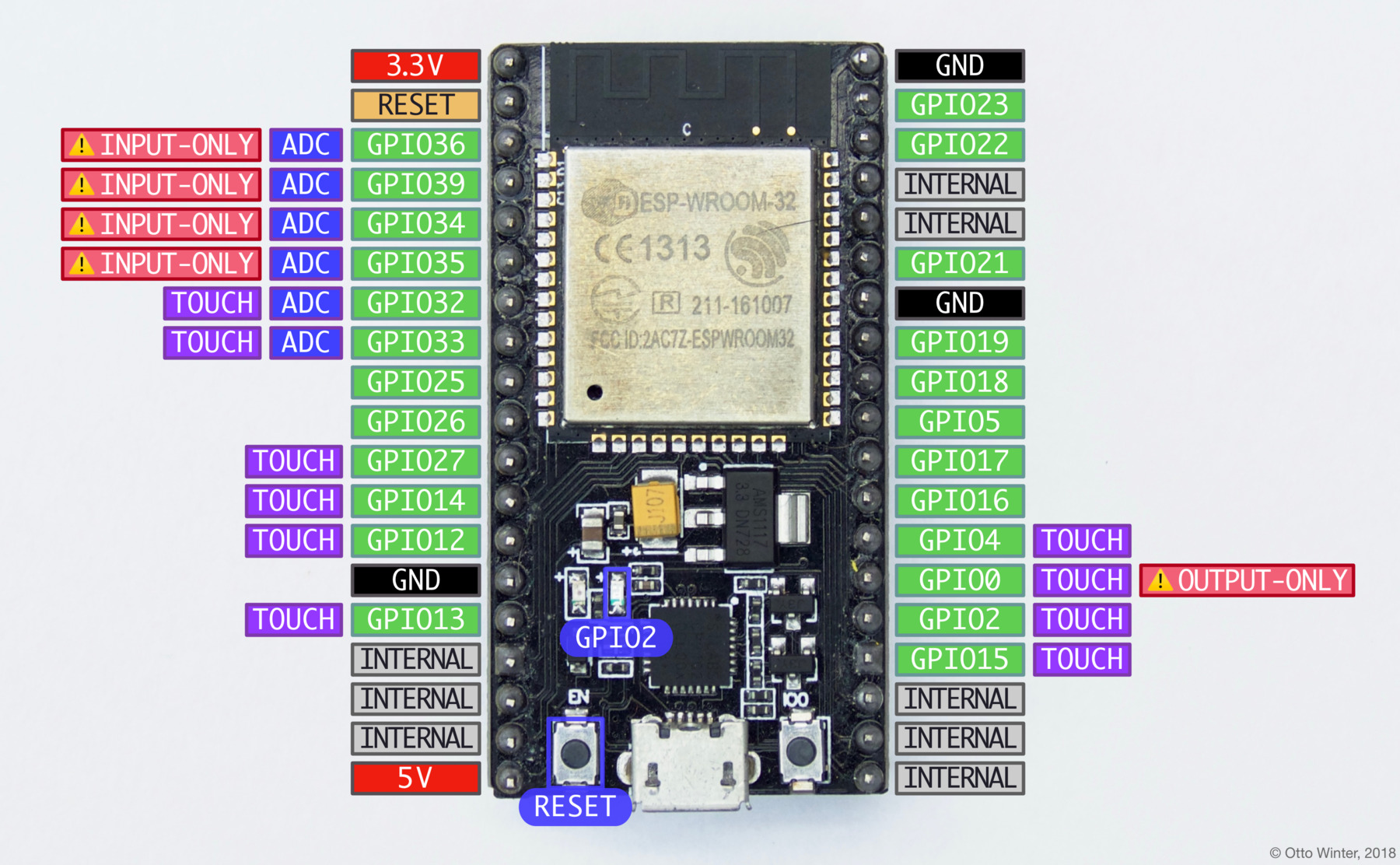
We can do a lot of cool projects with the touch sensor and the specifications of the board is given below:
| Number of cores | 2 |
| Wi-Fi | Yes |
| Bluetooth | Yes |
| RAM Bytes | 512 |
| Flash | 16MB |
| GPIO Pins | 36 |
For more details check my friend Jai's work here
NodeMCU ESP8266
The NodeMCU (Node MicroController Unit) is an open-source software and hardware development environment built around an inexpensive System-on-a-Chip (SoC) called the ESP8266. The ESP8266, designed and manufactured by Espressif Systems, contains the crucial elements of a computer: CPU, RAM, networking (WiFi), and even a modern operating system and SDK. That makes it an excellent choice for the Internet of Things (IoT) projects of all kinds. However, as a chip, the ESP8266 is also hard to access and use. You must solder wires, with the appropriate analog voltage, to its pins for the simplest tasks such as powering it on or sending a keystroke to the “computer” on the chip. You also have to program it in low-level machine instructions that can be interpreted by the chip hardware. This level of integration is not a problem using the ESP8266 as an embedded controller chip in mass-produced electronics. It is a huge burden for hobbyists, hackers, or students who want to experiment with it in their own IoT projects.
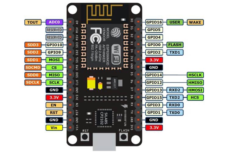
The following table shows the basic details of Node MCU
| Parameter Name | Value |
| Microcontroller | Tensilica 32-bit RISC CPU Xtensa LX106 |
| Operating Voltage | 3.3V |
| RAM Bytes | 256 |
| Input Voltage | 7-12V |
| Flash Memory | 4 MB |
| SRAM | 64 KB |
| Clock Speed | 80 MHz |
The Node MCU can be programmed using ESPlorer IDE as well as Aruino IDE. For more details regarding installation click here
Blink Program using Node MCU
Since I was given NodeMCU as a part of group assignment, I tried to test blink program in it using internal LED. To start with it first you need to add the board to Arduino IDE. For that visit this website. Before that you need to add driver for Node MCU for more details regarding that click here. The next step is to write the program for the blink. Since it's Arduino IDE it was very easy to program if you know about the pin numbers. The program and the testing is as follows:
    #define LED D0            // Led in NodeMCU at pin GPIO16 (D0).
void setup() {
pinMode(LED, OUTPUT);    // LED pin as output.
}
void loop() {
digitalWrite(LED, HIGH);// turn the LED off.(Note that LOW is the voltage level but actually
                        //the LED is on; this is because it is acive low on the ESP8266.
delay(1000);            // wait for 1 second.
digitalWrite(LED, LOW); // turn the LED on.
delay(1000); // wait for 1 second.
}
Console
    Executable segment sizes:
IROM   : 228624          - code in flash         (default or ICACHE_FLASH_ATTR)
IRAM   : 26756   / 32768 - code in IRAM          (ICACHE_RAM_ATTR, ISRs...)
DATA   : 1248  )         - initialized variables (global, static) in RAM/HEAP
RODATA : 688   ) / 81920 - constants             (global, static) in RAM/HEAP
BSS    : 24880 )         - zeroed variables      (global, static) in RAM/HEAP
Sketch uses 257316 bytes (24%) of program storage space. Maximum is 1044464 bytes.
Global variables use 26816 bytes (32%) of dynamic memory, leaving 55104 bytes for local variables. Maximum is 81920 bytes.
esptool.py v2.8
Serial port COM10
Connecting....
Chip is ESP8266EX
Features: WiFi
Crystal is 26MHz
MAC: b4:e6:2d:34:ec:ac
Uploading stub...
Running stub...
Stub running...
Configuring flash size...
Auto-detected Flash size: 4MB
Compressed 261472 bytes to 193131...
Wrote 261472 bytes (193131 compressed) at 0x
This video shows the blinking LED in Node MCU. Hurray!
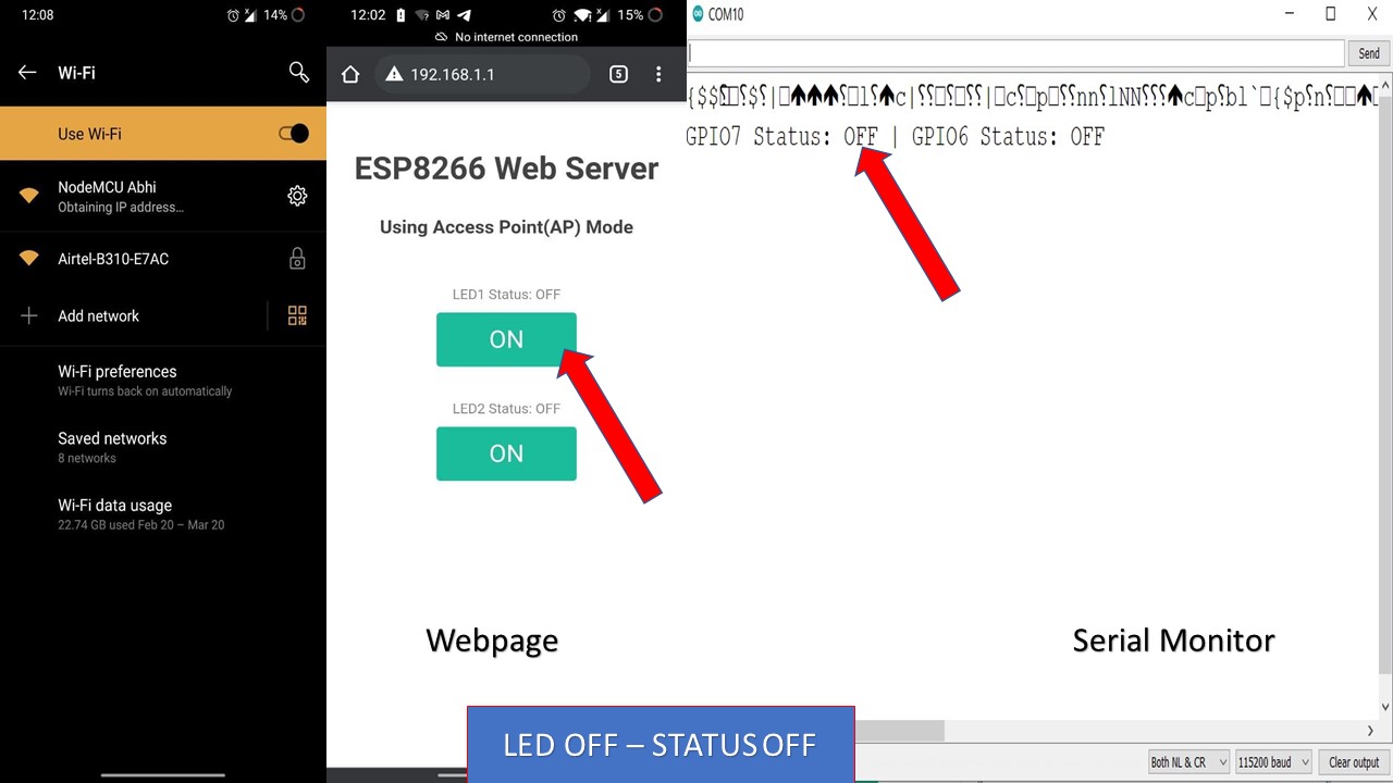
Creating ESP8266 NodeMCU Web Server In Arduino IDE
In this experiment, I had tried to create a Web Server in NodeMCU to control an LED remotely. The detailed reference on how to do it is provided here
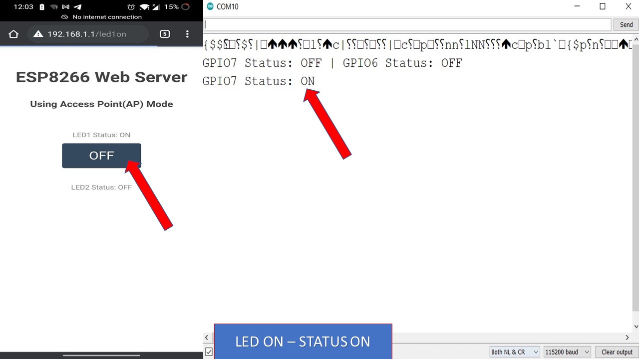
After uploading the sketch, open the Serial Monitor at a baud rate of 115200. And press the RESET button on ESP8266. If everything is OK, it will show HTTP server started message. Next, find any device that you can connect to a WiFi network – phone, laptop, etc. And look for a network called NodeMCU Abhi. Join the network with password 123456789. After connecting to your NodeMCU AP network, load up a browser and point it to 192.168.1.1 The NodeMCU should serve up a web page showing current status of LEDs and two buttons to control them. If take a look at the serial monitor at the same time, you can see status of NodeMCU’s GPIO pins. Now, click the button to turn LED1 ON while keeping an eye on the URL. Once you click the button, the ESP8266 receives a request for /led1on URL. It then turns the LED1 ON and serves a web page with status of LED updated. It also prints the status of GPIO pin on the serial monitor. You can test LED2 button and check that it works in a similar way.. Hurray that was an amazing experiment.
Code
    #include < ESP8266WiFi.h>
      #include < ESP8266WebServer.h >

      /* Put your SSID & Password */
      const char* ssid = "NodeMCU Abhi";  // Enter SSID here
      const char* password = "12345678";  //Enter Password here

      /* Put IP Address details */
      IPAddress local_ip(192,168,1,1);
      IPAddress gateway(192,168,1,1);
      IPAddress subnet(255,255,255,0);

      ESP8266WebServer server(80);

      uint8_t LED1pin = D7;
      bool LED1status = LOW;

      uint8_t LED2pin = D6;
      bool LED2status = LOW;

      void setup() {
        Serial.begin(115200);
        pinMode(LED1pin, OUTPUT);
        pinMode(LED2pin, OUTPUT);

        WiFi.softAP(ssid, password);
        WiFi.softAPConfig(local_ip, gateway, subnet);
        delay(100);

        server.on("/", handle_OnConnect);
        server.on("/led1on", handle_led1on);
        server.on("/led1off", handle_led1off);
        server.on("/led2on", handle_led2on);
        server.on("/led2off", handle_led2off);
        server.onNotFound(handle_NotFound);

        server.begin();
        Serial.println("HTTP server started");
      }
      void loop() {
        server.handleClient();
        if(LED1status)
        {digitalWrite(LED1pin, HIGH);}
        else
        {digitalWrite(LED1pin, LOW);}

        if(LED2status)
        {digitalWrite(LED2pin, HIGH);}
        else
        {digitalWrite(LED2pin, LOW);}
      }

      void handle_OnConnect() {
        LED1status = LOW;
        LED2status = LOW;
        Serial.println("GPIO7 Status: OFF | GPIO6 Status: OFF");
        server.send(200, "text/html", SendHTML(LED1status,LED2status));
      }

      void handle_led1on() {
        LED1status = HIGH;
        Serial.println("GPIO7 Status: ON");
        server.send(200, "text/html", SendHTML(true,LED2status));
      }

      void handle_led1off() {
        LED1status = LOW;
        Serial.println("GPIO7 Status: OFF");
        server.send(200, "text/html", SendHTML(false,LED2status));
      }

      void handle_led2on() {
        LED2status = HIGH;
        Serial.println("GPIO6 Status: ON");
        server.send(200, "text/html", SendHTML(LED1status,true));
      }

      void handle_led2off() {
        LED2status = LOW;
        Serial.println("GPIO6 Status: OFF");
        server.send(200, "text/html", SendHTML(LED1status,false));
      }

      void handle_NotFound(){
        server.send(404, "text/plain", "Not found");
      }

      String SendHTML(uint8_t led1stat,uint8_t led2stat){
        String ptr = "< !DOCTYPE html > < html >\n";
        ptr +="< head > < meta name=\"viewport\" content=\"width=device-width, initial-scale=1.0, user-scalable=no\">\n";
        ptr +="< title>LED Control< /title>\n";
        ptr +="< style>html { font-family: Helvetica; display: inline-block; margin: 0px auto; text-align: center;}\n";
        ptr +="body{margin-top: 50px;} h1 {color: #444444;margin: 50px auto 30px;} h3 {color: #444444;margin-bottom: 50px;}\n";
        ptr +=".button {display: block;width: 80px;background-color: #1abc9c;border: none;color: white;padding: 13px 30px;text-decoration: none;font-size: 25px;margin: 0px auto 35px;cursor: pointer;border-radius: 4px;}\n";
        ptr +=".button-on {background-color: #1abc9c;}\n";
        ptr +=".button-on:active {background-color: #16a085;}\n";
        ptr +=".button-off {background-color: #34495e;}\n";
        ptr +=".button-off:active {background-color: #2c3e50;}\n";
        ptr +="p {font-size: 14px;color: #888;margin-bottom: 10px;}\n";
        ptr +="< /style>\n";
        ptr +="< /head>\n";
        ptr +="< body>\n";
        ptr +=" < h1>ESP8266 Web Server< /h1>\n";
        ptr +="< h3>Using Access Point(AP) Mode< /h3>\n";

         if(led1stat)
        {ptr +="< p>LED1 Status: ON< /p>< a class=\"button button-off\" href=\"/led1off\">OFF< /a>\n";}
        else
        {ptr +="< p>LED1 Status: OFF< /p>< a class=\"button button-on\" href=\"/led1on\">ON< /a>\n";}

        if(led2stat)
        {ptr +="< p>LED2 Status: ON< /p>< a class=\"button button-off\" href=\"/led2off\">OFF< /a>\n";}
        else
        {ptr +="< p>LED2 Status: OFF< /p>< a class=\"button button-on\" href=\"/led2on\">ON< /a>\n";}

        ptr +="< /body>\n";
        ptr +="< /html>\n";
        return ptr;
      }