The Datasheet of a microcontroller is vast compost of information, much of it being not immediately useful. The main things to look out for are:
Features:
High Performance, Low Power AVR® 8-Bit Microcontroller
RISC Architecture
Program Memory Type: Flash
Program Memory (KB): 4
CPU Speed (MIPS): 20
RAM Bytes: 256
Data EEPROM (bytes): 256
Digital Communication Peripherals: 1-SPI, 1-I2C
Capture/Compare/PWM: 1 Input Capture, 1 CCP, 4PWM
Operating Voltage: 1.8 – 5.5V
Speed Grade:
0 – 10 MHz @ 2.7 – 5.5V
0 – 20 MHz @ 4.5 – 5.5V
Temperature Range: -40°C to +85°C
Internal Calibrated Oscillator of 8MHz
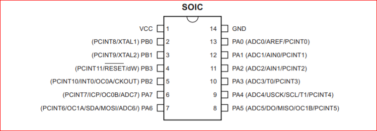
Pinout:
VCC:
Supply voltage.
GND:
Ground
Port B (PB3:PB0):
Port B is a 4-bit bi-directional I/O port with internal pull-up resistors (selected for each bit). The Port B output buffers have symmetrical drive characteristics with both high sink and source capability except PB3 which has the RESET capability. To use pin PB3 as an I/O pin, instead of RESET pin, program (‘0’) RSTDISBL fuse. As inputs, Port B pins that are externally pulled low will source current if the pull-up resistors are activated. The Port B pins are tri-stated when a reset condition becomes active, even if the clock is not running.
RESET:
Reset input. A low level on this pin for longer than the minimum pulse length will generate a reset, even if the clock is not running and provided the reset pin has not been disabled. The minimum pulse length is given page 177 of the datasheet. Shorter pulses are not guaranteed to generate a reset. The reset pin can also be used as a (weak) I/O pin.
Port A (PA7:PA0):
Port A is a 8-bit bi-directional I/O port with internal pull-up resistors (selected for each bit). The Port A output buffers have symmetrical drive characteristics with both high sink and source capability. As inputs, Port A pins that are externally pulled low will source current if the pull-up resistors are activated. The Port A pins are tri-stated when a reset condition becomes active, even if the clock is not running.
Registers:
Directional registor: assigned by code "DDRA/DDRB" are the registors for Directing the registor normally used for assigning certain value to the registor.
Input registor: assigned by "PINA/PINB" are the input registor to take input from switches or sensors.
Outut registor: assigned by "PORTA/PORTB" are the output registor to supply signal to the output or actuators
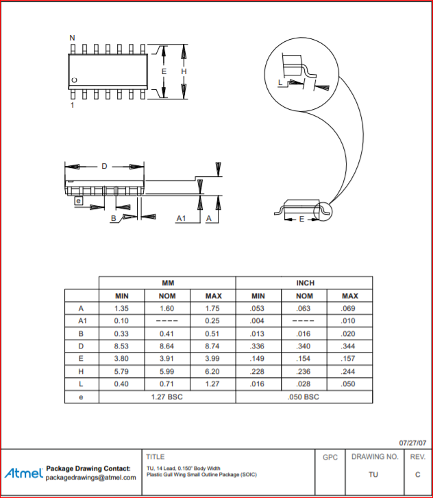
Dimensions:
First, I installed 'avrdude', 'gcc-avr', 'avr-libc' using sudo apt install.
You can check if the installation was success by entering 'avrdude' in the terminal.
In the Electronics Design week, we have fabricated a board using ATTiny84
I really want to code using 'Rust Lang' instead of 'C' or 'Assembly', but I do not know if Rust is supported in AVR boards, yet.
By the way, 'avr-libc' is the toolchain and 'avr-gcc' is the compiler.
Toolchain vs Compiler: If we define the word "host" to mean a computer on which you are compiling, and "target" as the computer on which you want to run the code, then a native compiler is one where the target and the host are the same (kind). A cross-compiler is a compiler where the target is different from the host.
A toolchain is the set of compiler + linker + librarian + any other tools you need to produce the executable (+ shared libraries, etc) for the target. A debugger and/or IDE may also count as part of a toolchain. here
                        void setup() {
                            DDRA = (1 << PA2);//OUTPUT LED on PA2
                          }

                          void loop() {
                            PORTA = (1 << PA2);//LED is ON
                            delay(1000);
                            PORTA &= ~(1 << PA2);//LED is OFF
                            delay(1000);
                          }
I tried uploading this code using Arduino IDE. It was working before, but it isn't now. Tried for an hour or so. The problem turned out to be with the resonators.
I re-soldered it the oscillator again. Tried uploading again, It worked.
Lost the image while minimizing
DDRB |= (1 << 2) This particular code changes the value in 2nd pin of DDRB into '1', and leaves the rest as it was before.
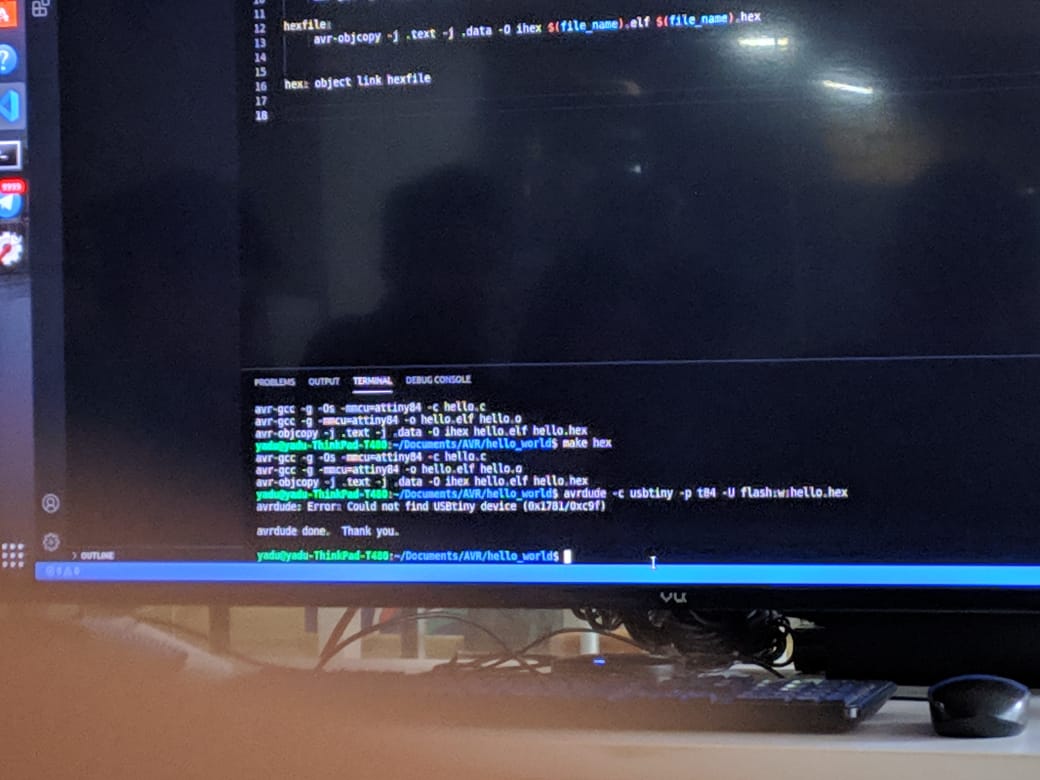
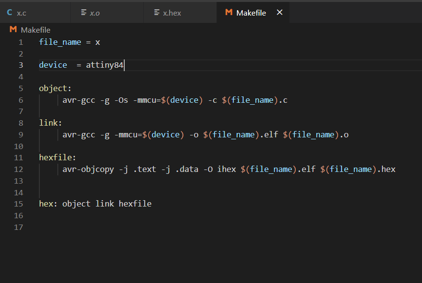
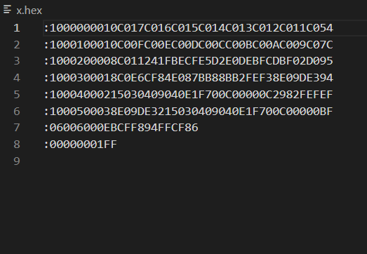
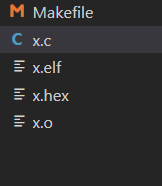
Making Hex. Flashing.
How do we know the register names DDRA, PORTA, PORTB? - it is in the datasheet
Configured the Makefile for programming using avrdude toolchain.
I enetered make hex into the terminal. It failed.
Re-ordered the #define F_CPU 20000000 line, and it worked
You can tryout ASCII-HEX converter here, for better understanding: here
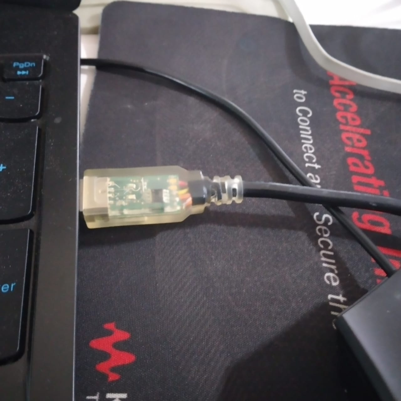
Next, use this command to flash the connected ATTiny84 controller
The breakdown:
-c usbtiny: Use USBTiny as the ISP
-p t84: ATTiny84 is the target device
-U flash:v:x:hex : Flash using the specified hex file.
The thing is, I have programmed relatively non-trivial things in ATTiny84 in the Electronics Design week. Therefore, I intend to move on to other chips as soon as possible.
I am following this article to see how to set-up ESP32 and start programming it: here
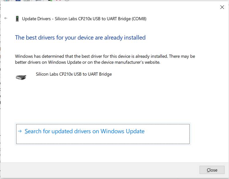
I connected ESP32 to my PC using USB.
Windows was smart enough to install the required driver.
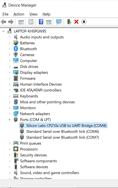
The device set up and ready for serial communication in COM Port 8.
Next thing is establishing serial communication through a SSH client. Conventionally, it is done using something like PuTTY SSH. But, fortunately, this microsoft article says that the new microsoft terminal has a built-in SSH Client, which I am going to use - Windows-Terminal SSH.
I am encountering some problems while trying to change the permissions for my COM Port. This step is essential to be able to write to the COM PORT.
This seems to be WSL specific problem - Github Issue.
Later, I learned that Microsoft has recently upgraded WSL to be able to communicate with COM Ports directly - WSL support for linux
I have successfully changed the permissions of COMM PORT 8, and then I am installing the necessary toolchain and frameworks for ESP32.
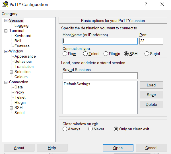
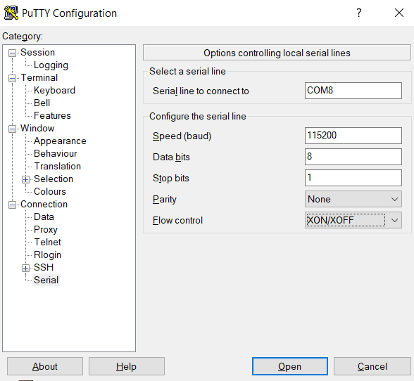
Okay, I have tried hard to do it without PuTTY, but I think I am gonna do it with PuTTY itself - here
Click on Serial. Put in the relevant COM Port. Enter the relevant details
By the way, remember to set the environment variables everytime a new instance of the terminal is opened. I wasted 1 hr on this.
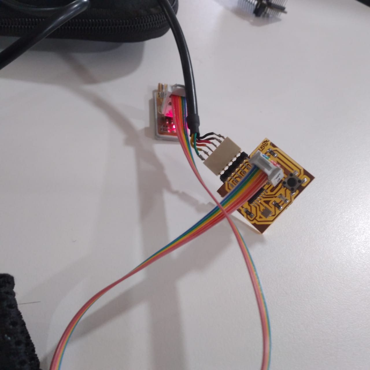
Now, I am going back to ATTiny84, we built in the Electronics Design week and programming it using Arduino IDE.
When you read the pinout of any chip, it is important to realize the pin no. for the relevant environment. For example, For arduino pins, if it is 0, 1, then it is 12, 13 in PORT Pins
SoftwareSerial is an inbuilt library in Arduino IDE that enables Serial Communication.
9600 is the baud rate.
Upload using programmer
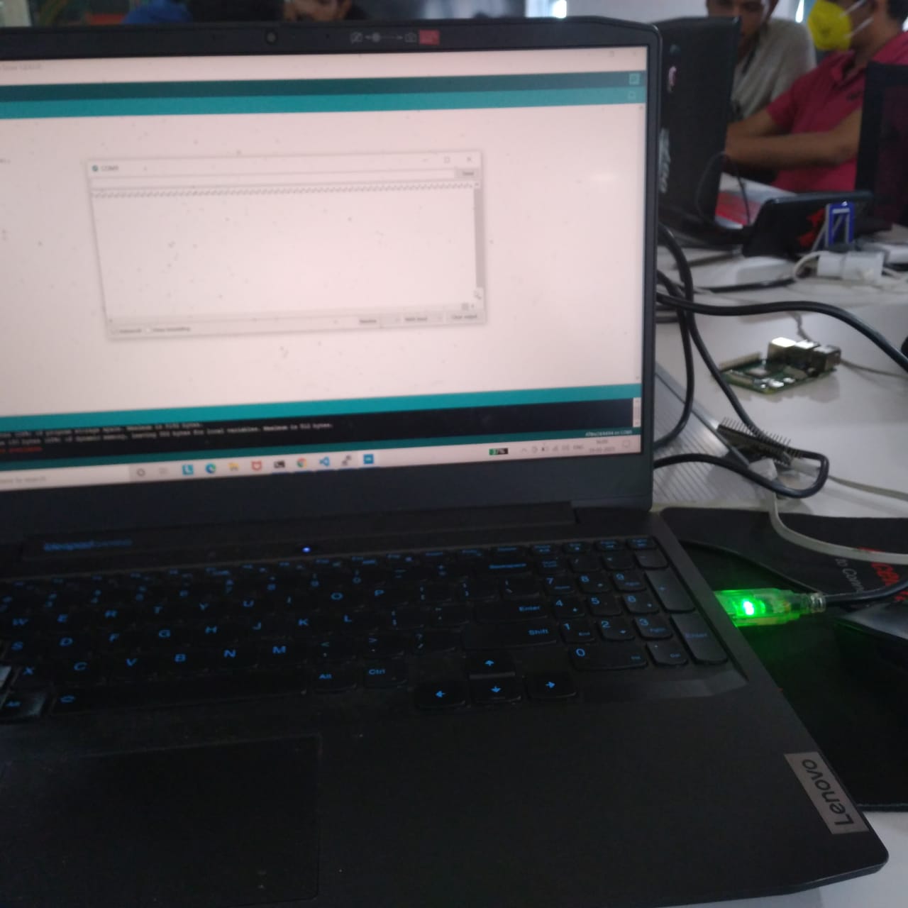
You will see the green LED light up, at the moment of upload.
Once the uploading is done, Choose the appropriate port by checking in the Device Manager.
Lost image while minimizing
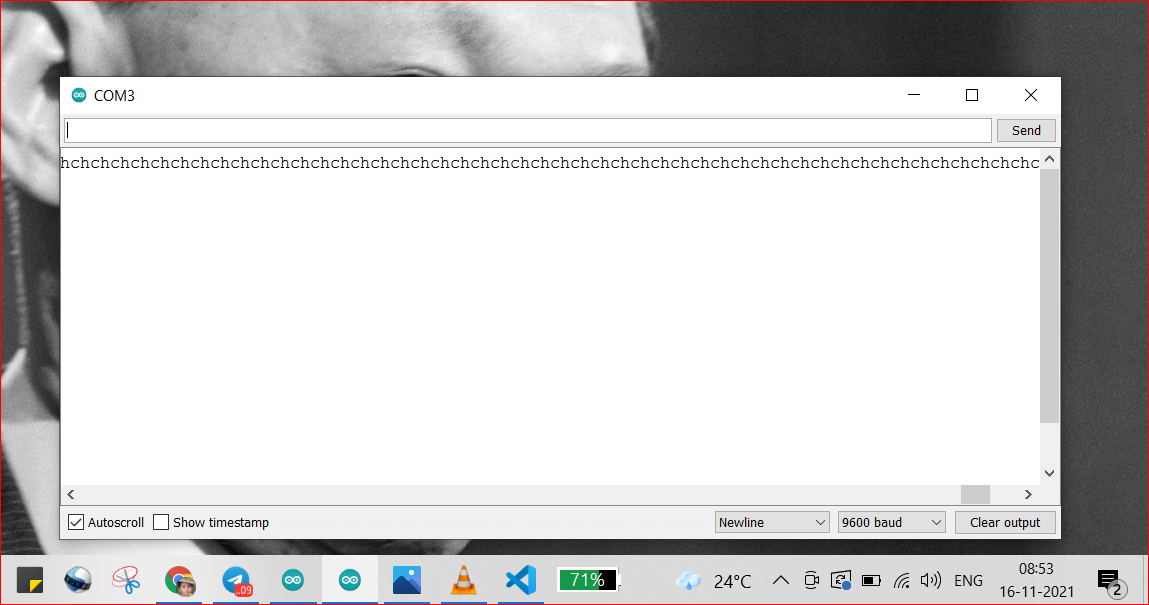
Serial Communication Success!
[UPDATED]
Video of serial communication[UPDATED].
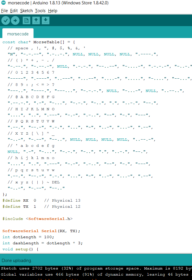
Trying out the morse code program, I wrote in the Electronics Design week
It is a simple code which outputs '.' and '-' in morsecode fashion for 'dits' and 'dahs' respectively, and lights up the LED for 1 second, if it is a 'dit' and 3 seconds if it is a 'dah'.
It works!
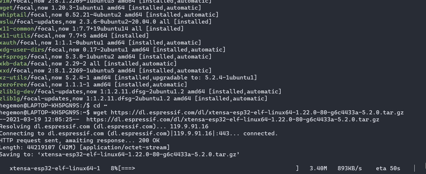
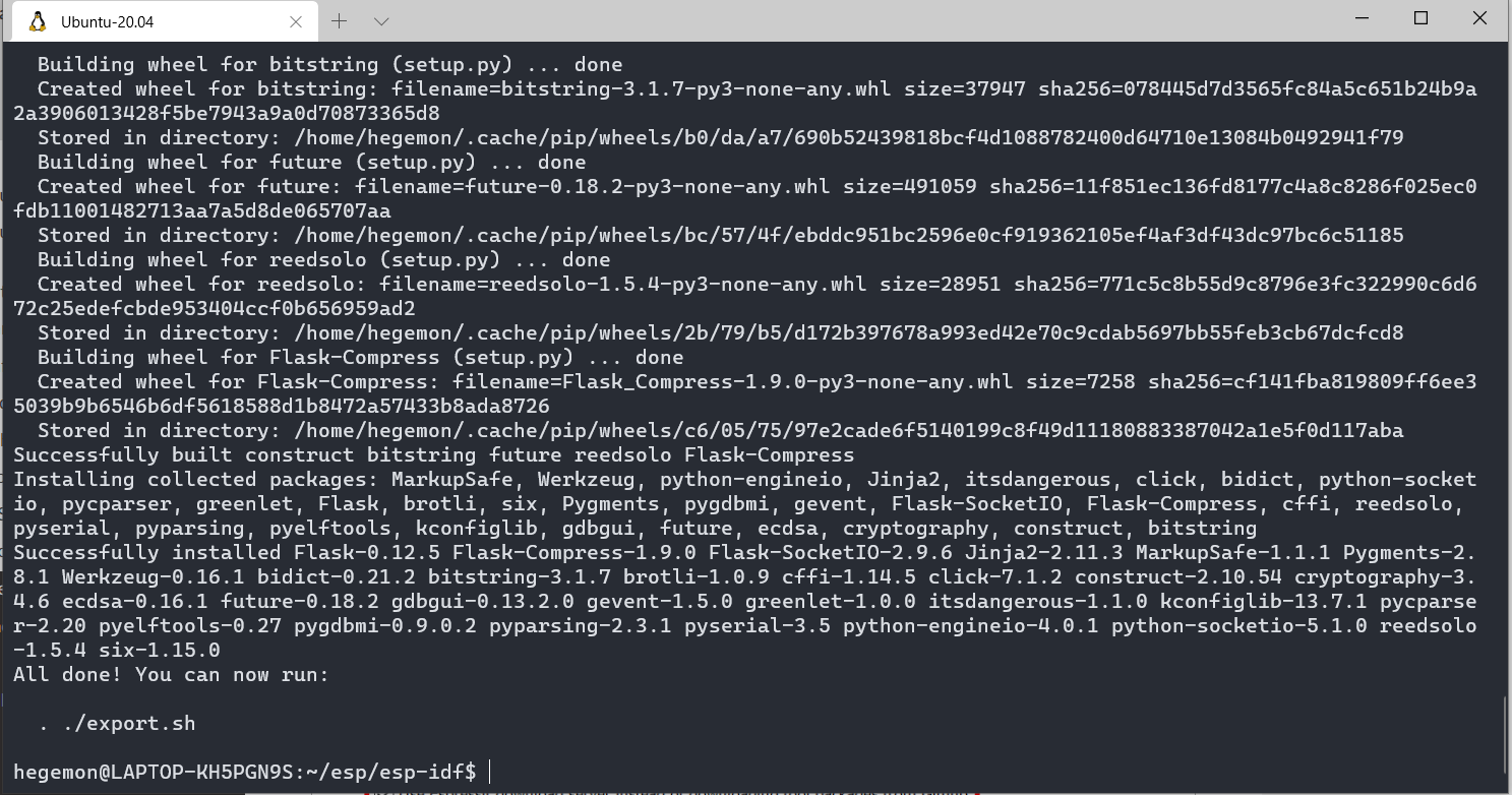
Now coming back to the ESP32 toolchain installation, I consulted the official
ESP-IDF documentation, and got it successfully installed.
Lost image while minimizing
Nonetheless, if you are using Windows like I am, I would recommend you take the standard windows installation route, instead of the one I took: ESP-IDF Windows Installation Process.
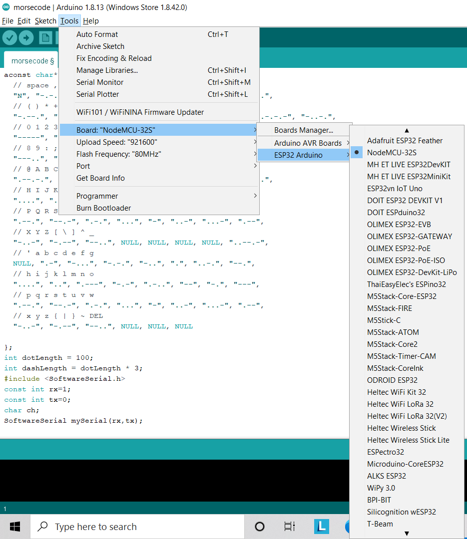
Next up, I am going to use Arduino IDE to program the ESP32 board.
This is the installation process, I followed: here
Next, I verified the installation
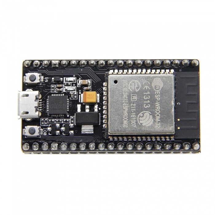
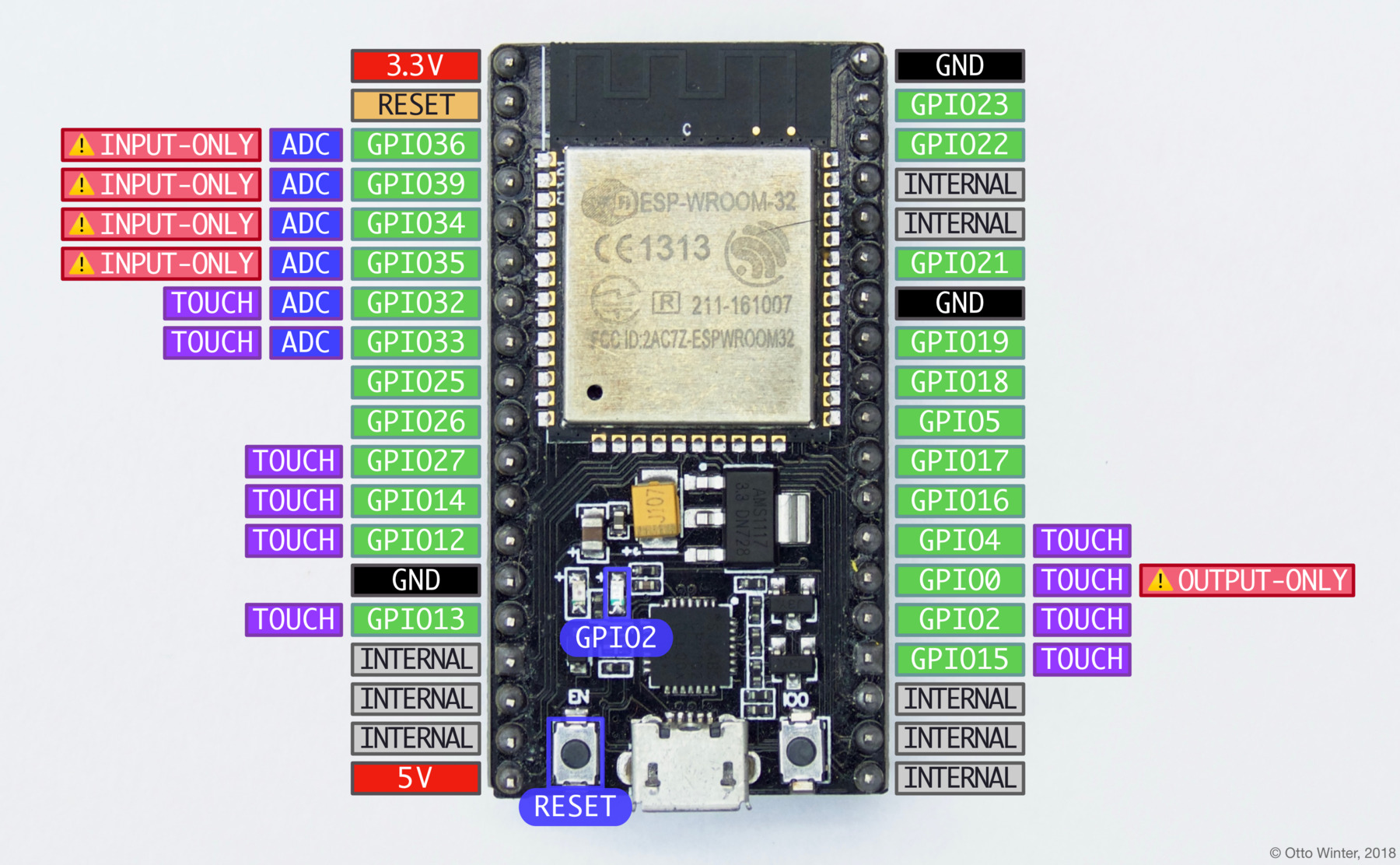
NodeMCU ESP32S
The NodeMCU ESP-32S is one of the development board created by NodeMcu to evaluate the ESP-WROOM-32 module. It is based on the ESP32 microcontroller that boasts Wifi, Bluetooth, Ethernet and Low Power support all in a single chip.
I have learned that there are essentially three ways to build your NodeMCU firmware: cloud build service, Docker image, dedicated Linux environment (possibly VM).
This is the cloud service to build the firmware for your node-mcu devices: node-mcu-build
I am, preliminarily, choosing as few modules as possible:
file: The file module provides access to the file system and its individual files.
GPIO: This module provides access to the GPIO (General Purpose Input/Output) subsystem.
timer: The tmr module allows access to simple timers, the system counter and uptime.
UART: The UART (Universal asynchronous receiver/transmitter) module allows configuration of and communication over the UART serial port.
WiFi Module
net Module
node: The node module provides access to system-level features such as sleep, restart and various info and IDs.
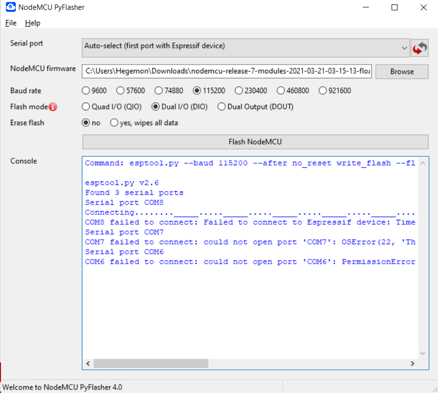
NodeMCU Cloud-Based custom build is finished, and ready to download!
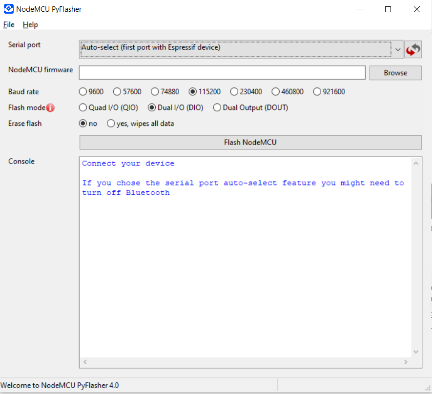
You can use this cool GUI console to flash your Node-MCU, if you are on windows: here
Failed to connect.
Lost image while minimizing
This article says that this problem can be solved by holding down the BOOT button: here
Did not work.
NodeMCU ESP32s in Arduino IDE
I have decided to use Arduino IDE to program my NodeMCU ESP32S.
Follow this tutorial to set-up the ESP32S board in your Arduino IDE: here
Still did not work. This was the error:
Arduino: 1.8.13 (Windows Store 1.8.42.0) (Windows 10), Board: "NodeMCU-32S, 80MHz, 921600"

                  Sketch uses 198856 bytes (15%) of program storage space. Maximum is 1310720 bytes.

                  Global variables use 13276 bytes (4%) of dynamic memory, leaving 314404 bytes for local variables.
                  Maximum is 327680 bytes.

                  esptool.py v3.0-dev

                  Serial port COM8

                  Traceback (most recent call last):

                    File "esptool.py", line 3682, in

                    File "esptool.py", line 3675, in _main

                    File "esptool.py", line 3329, in main

                    File "esptool.py", line 263, in __init__

                    File "site-packages\serial\__init__.py", line 88, in serial_for_url

                    File "site-packages\serial\serialwin32.py", line 62, in open

                  serial.serialutil.SerialException: could not open port 'COM8': WindowsError(5, 'Access is denied.')

                  Failed to execute script esptool

                  the selected serial port Failed to execute script esptool

                   does not exist or your board is not connected


                  This report would have more information with
                  "Show verbose output during compilation"
                  option enabled in File -> Preferences.
I am troubleshooting it by going through this github issue: github issue
They recommend me to check the driver-installaton. I checked. The Windows says everything is fine:
At last, got Arduino IDE working.
The problem was I had another program trying to connect to COM PORT 8. I closed it. It worked.
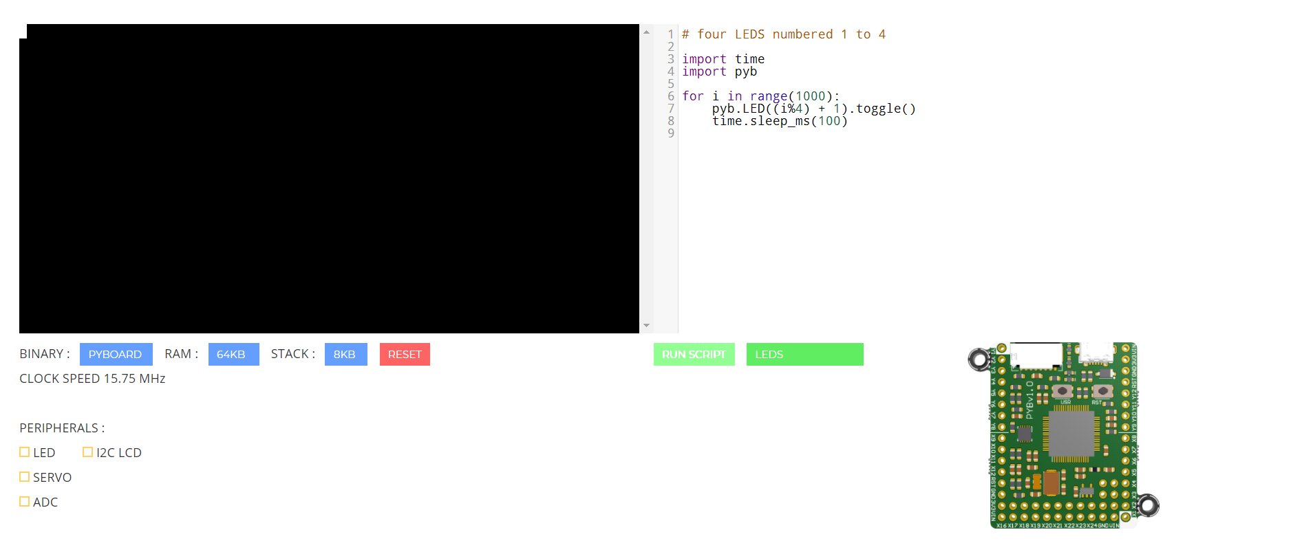
Using Mircopython Online.
I would have installed micropython locally, but I am away from a good source of internet connection. I shall do it in the future.
This is the interface of micropython-online:
It has a terminal, editor, circuit. Beginners can try different scripts to get acquianted with the workflow without having to download and install the whole thing.
Documentation for micropython lang and their std-lib: here
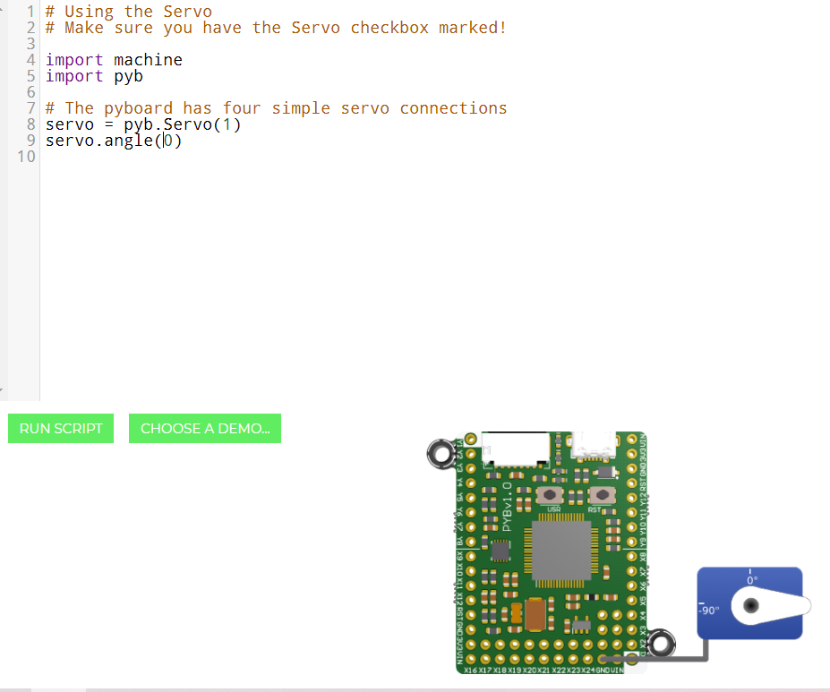
Code for changing the angle of a servo in micropython:
# Make sure you have the Servo checkbox marked!

import machine
import pyb

# The pyboard has four simple servo connections
servo = pyb.Servo(1)
servo.angle(0)
It is definitely a cool implementation of the python std-lib, I will do more with Micropython in the future.
Group Assignment:
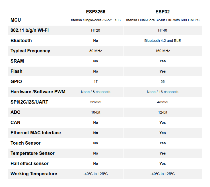
Now coming back to ESP32S by Node-MCU, which I am doing for the Group Assignment. How does it compare to it's closer cousin ESP8266
Go through this instructables article for more nitty-gritties: here
Another cool thing about ESP32S is it has 10 in-built touch sensors. This is the code to on-off the LED based on touch.
                    #define TOUTCH_PIN T0 // ESP32 Pin D4
#define LED_PIN 2
int touch_value = 100;

void setup()
{
  Serial.begin(115200);
  delay(1000); // give me time to bring up serial monitor
  Serial.println("ESP32 Touch Test");
  pinMode(LED_PIN, OUTPUT);
  digitalWrite (LED_PIN, LOW);
}

void loop()
{
  touch_value = touchRead(TOUTCH_PIN);
  Serial.println(touch_value);  // get value using T0
  if (touch_value < 50)
  {
    digitalWrite (LED_PIN, HIGH);
  }
  else
  {
    digitalWrite (LED_PIN, LOW);
  }
  delay(1000);
}
It worked. Here's the video(Since this vid is non-essential, I chose to put it in YT):
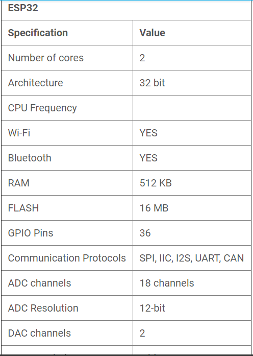
Finally, ESP32S specifications, in one place:
Scanning for WiFi using ESP32S WiFi Module:
#include "WiFi.h"
String networkSSID = "";
int strengthSignal = -9999;
void setup()
{
// Initialize Serial to log in Serial Monitor
Serial.begin(9600);
// configuring the mode of operation of WiFi as station
WiFi.mode(WIFI_STA);//WIFI_STA is a constant indicating the station mode
// disconnect from the access point if it is already connected
WiFi.disconnect();
delay(100);
// Serial.println("Setup done");
}
void loop()
{
// Serial.println("scan start");
// performs the scanning of available networks
int n = WiFi.scanNetworks();
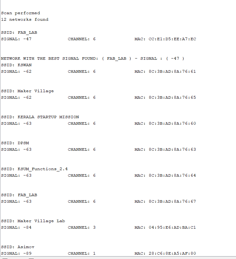
Serial.println("Scan performed");
//check if you have found any network
if (n == 0) {
Serial.println("No network found");
} else {
networkSSID = "";
strengthSignal= -9999;
Serial.print(n);
Serial.println(" networks found\n");
for (int i = 0; i < n; ++i) {
//print on serial monitor each of the networks found
Serial.print("SSID: ");
Serial.println(WiFi.SSID(i)); //network name (ssid)
Serial.print("SIGNAL: ");
Serial.print(WiFi.RSSI(i)); //signal strength
Serial.print("\t\tCHANNEL: ");
Serial.print((int)WiFi.channel(i));
Serial.print("\t\tMAC: ");
Serial.print(WiFi.BSSIDstr(i));
Serial.println("\n\n");
if(abs(WiFi.RSSI(i)) < abs(strengthSignal))
{
strengthSignal = WiFi.RSSI(i);
networkSSID = WiFi.SSID(i);
Serial.print("NETWORK WITH THE BEST SIGNAL FOUND: ( ");
Serial.print(networkSSID);
Serial.print(" ) - SIGNAL : ( ");
Serial.print(strengthSignal );
Serial.println(" )");
}
delay(10);
}
}
Serial.println("\n------------------------------------------------------------------------------------\n");
// interval of 5 seconds to perform a new scan
delay(5000);
}


 [UPDATED]