Final Project progress
INTRODUCTION
Brief
My final project is a general-purpose data logger, which will measure the data from a remote sensor; I will be using a water level sensor as a showcase, transmit the data using a long-distance RF communication to internet connect board which will send data online to be saved and viewed late.
Ideation
The project idea came from my work, I am an electronics engineer in a fablab Irbid which is a part of a hardware accelerator. startups usually come to me for a solution to log data in their initial testing period, and I find myself helping them build almost similar logging devices, with the difference of the logging sensor, and the way it logs the data online. In this project, I will try to build an open-source general-purpose data logger, where startups can just design and build the sensor they need and the rest is ready to produce.
Initial plan
I notice that some data logging devices can connect to wifi directly, while others are remote, which means they need to send the data through a distance longer than the wifi range to another device that can go online. From there I started planning my final project to be able to have these two options together, starting from one device which I will call the gateway, this device will be able to connect to wifi, be powered by an AC to DC power adapter, the gateway will have a 3 wire jack that can connect to a sensor. The jack will carry power through 5V and GND to power the sensor PCB, and a UART RX pin to receive the data from the sensor to upload it.
In case the sensor is remote, I will design an RF transmitter and receiver devices. The transmitter device will be battery-powered and will have the same jack as the gateway, it will power the sensor, receives data from it, then sends it through RF to the RF receiver device. The RF receiver device will connect to the gateway, having the same output wire as the sensor to be connected in its place, it will be powered by the gateway, receives data from the RF transmitter, and send it to the gateway through UART exactly like the sensor would, therefore the gateway will handle it the same as the sensor. I will add a charging station at the gateway, to make it easy to charge the RF transmitter device battery.
A few design considerations I should keep in mind building this project, first, the battery powering the RF transmitter device should be easily removed to be able to connect it to the charging station on the gateway, it should have a mounting mechanism that enables connecting it on both devices easily. Second, the RF transmitter device and the battery should be waterproof in case it is installed outdoor. Third, the RF receiver might not be needed if the sensor is connected to the gateway directly, therefore I should keep in mind to design them in a way to be mounted together seamlessly if needed, and if not it can be removed without affecting the looks and function of the gateway.
I will start by design and programming the electronics parts, there are four needed, a sensor to test the logging, the gateway, the RF transmitter, and the RF receiver. after the electronics are built and tested, I can work on their casing, keeping in mind the consideration mentioned in the previous paragraph.
I am expecting that the electronics design, production, and testing would take a couple of weeks, and the casing design and production will take one. I am pushing my self as I changed my final project Idea and short on time.
ELECTRONICS
This section will describe the electronics made for this project.
PCBs design
This section will describe the electronics designs of the PCBs in the project.
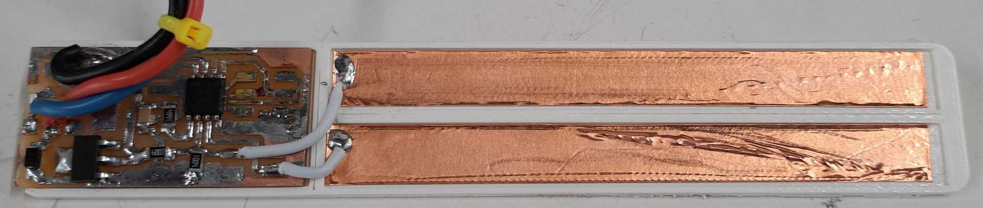
Sensor
I am using the step response sensor to measure the water level, the project is a generic data logger, any sensor would work, it just has to have its PCB that measures the sensor data and send it using UART to either the esp8266 or the NRF905 PCBs that is detailed in the Gateway and RF devices sections.
The sensor simply detects the capacitance between two conductives, one of these conductives the transmitter pin, is charged with 5V using the GPIO peripheral, then discharged. after each charge and discharge, I measure the analog voltage at the receiver pin, the receiver pin is held at half the VCC voltage using a voltage divider between two 1M ohm resistors one connected to the ground and the second to VCC as shown in the schematic below.
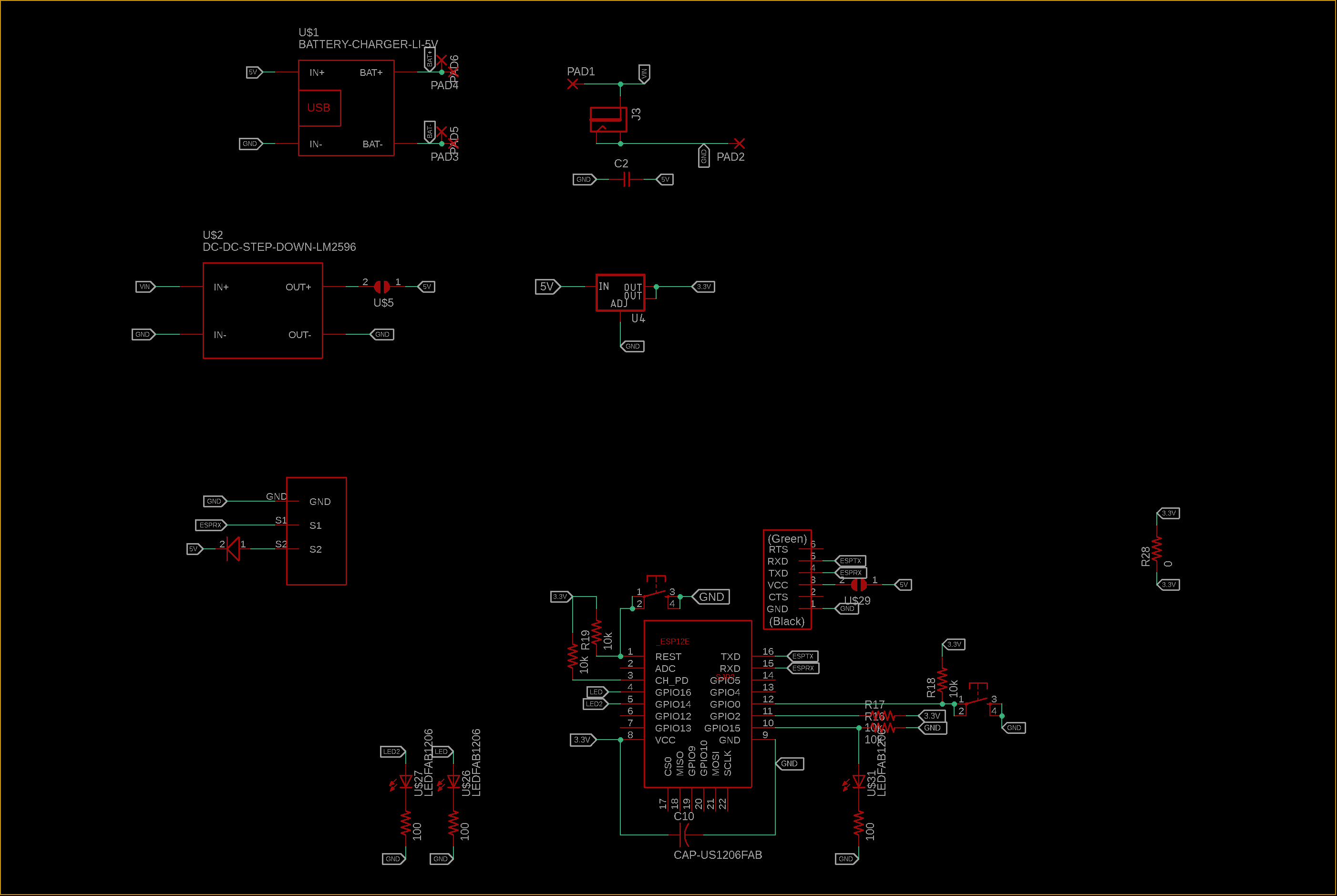
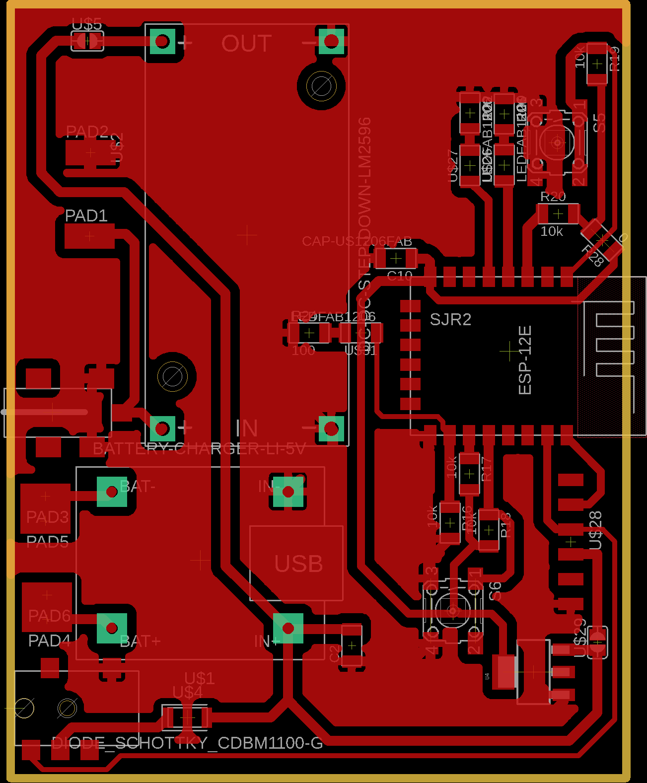
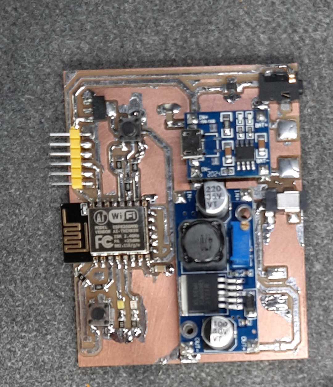
Gateway
The gateway’s job is to get UART data through a 2.5mm audio jack and post it online, I can either connect the sensor directly to it or connect the RF receiver. The 2.5mm audio jack has 3 terminals, 2 to power what every board is connected to it, and the third is for UART receiving data. This part is powered through an ac power adapter, it has a battery charging module to charge the spare battery for the RF transmitter board.
I started by laying out a block diagram for the PCB.
Here is the electronics schematic from AutoDesk Eagle.
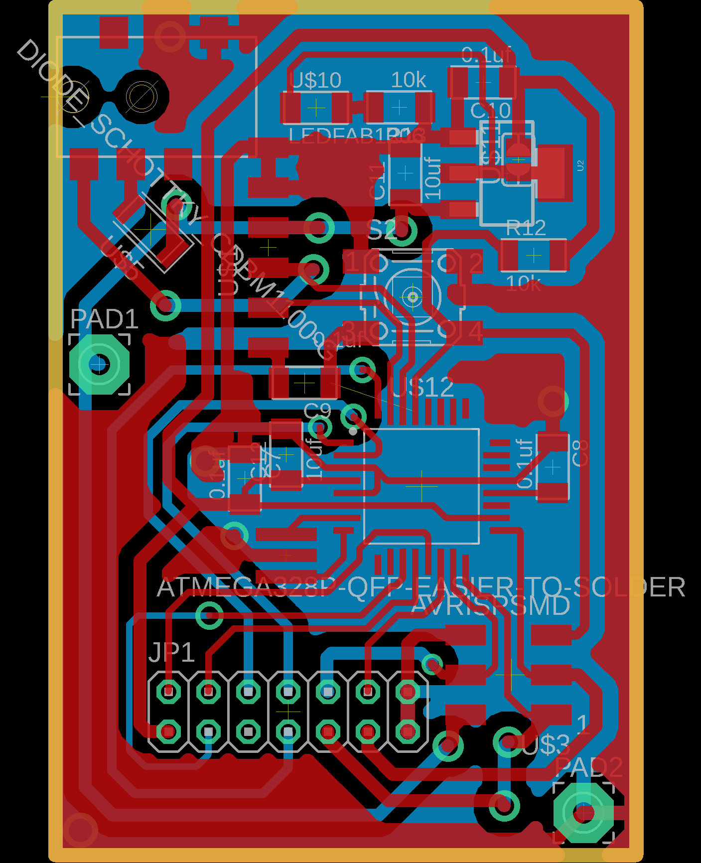
Here is the electronics Board from AutoDesk Eagle.
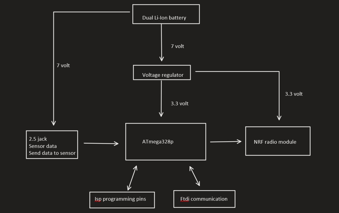
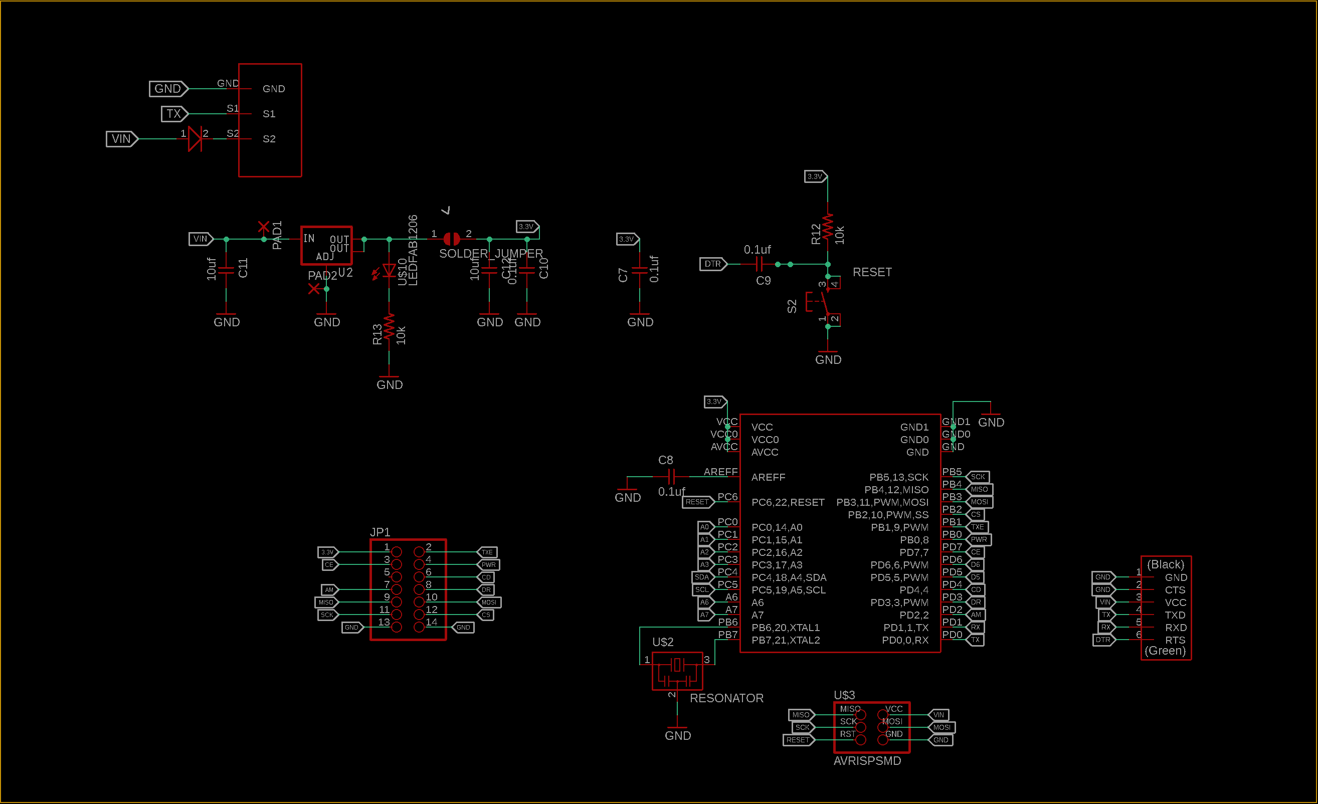
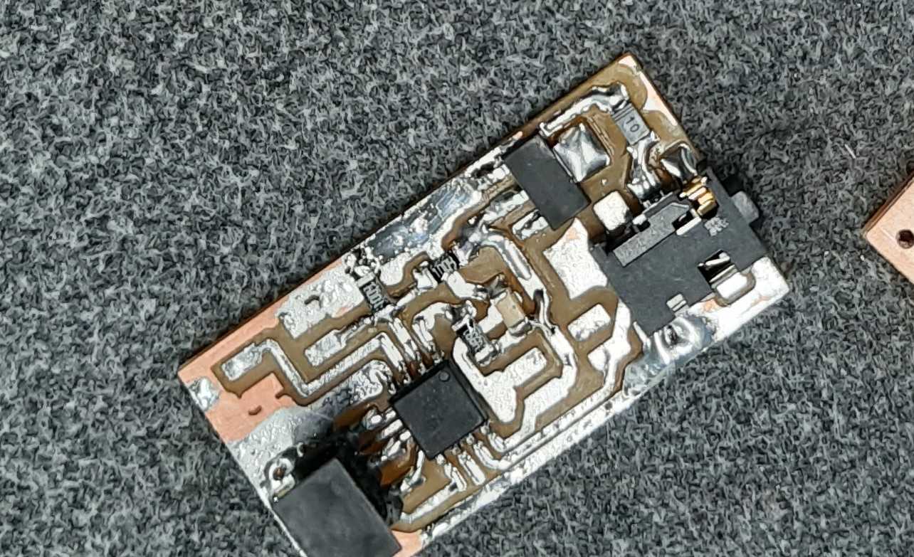
RF transmitter
The RF transmitter part job is to send the sensor data through long rages if the sensor is placed in a remote location, this part is battery powered, it shared power to the sensor board, gets the data from the sensor through a 2.5mm jack.
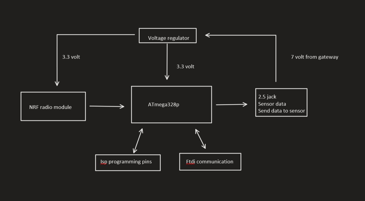
I started by laying out a block diagram for the PCB.
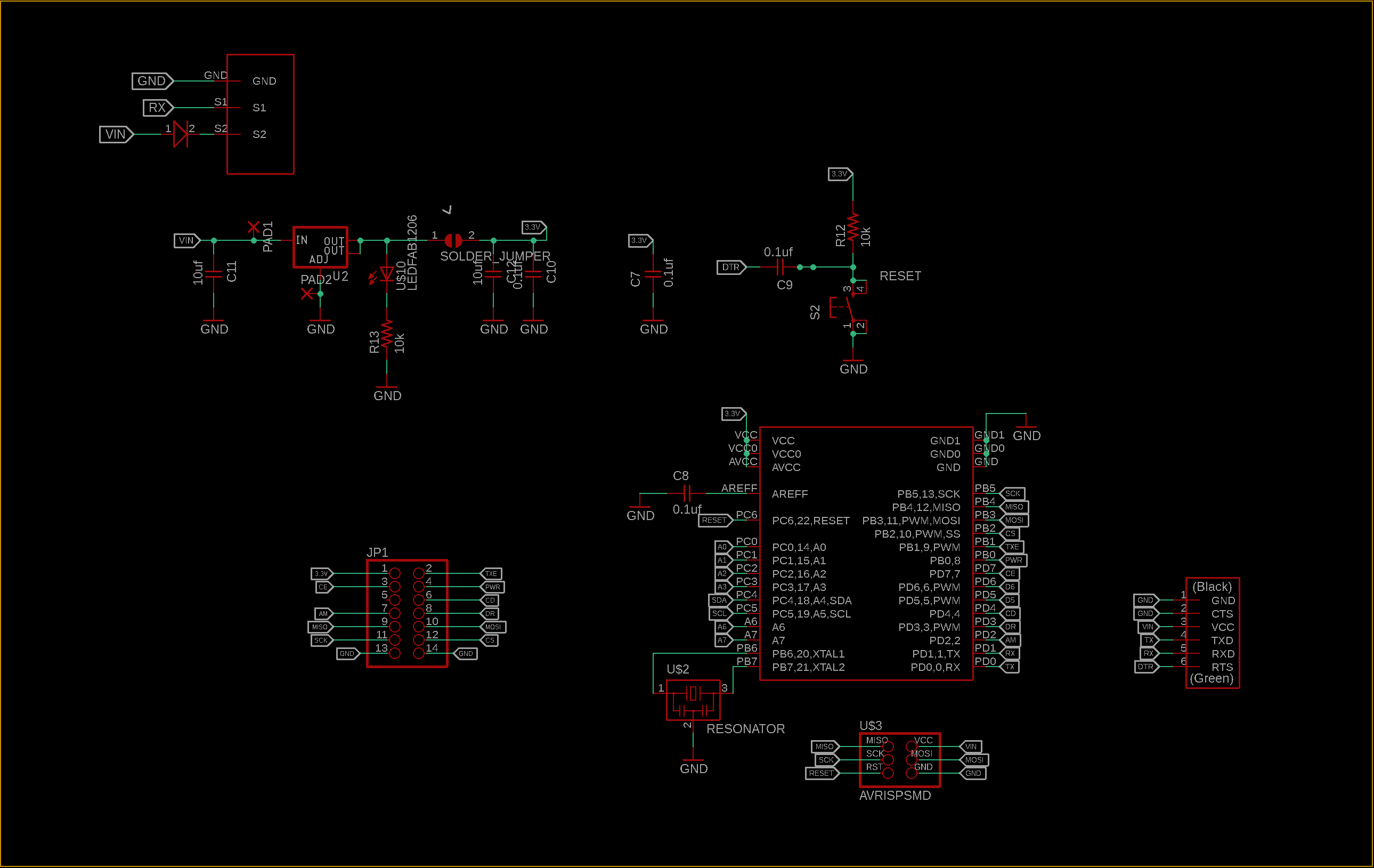
Here is the electronics schematic from AutoDesk Eagle.
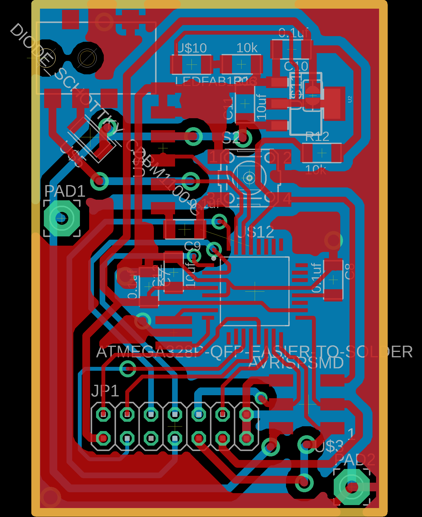
Here is the electronics Board from AutoDesk Eagle.
RF receiver
The RF receiver part job is to send the sensor data through UART using the same way that the sensor sending data to the gateway, it gets the data from the RF transmitter part, this part takes power from the gateway through the 2.5mm audio jack exactly like the sensor.
I started by laying out a block diagram for the PCB.
Here is the electronics schematic from AutoDesk Eagle.
Here is the electronics Board from AutoDesk Eagle.
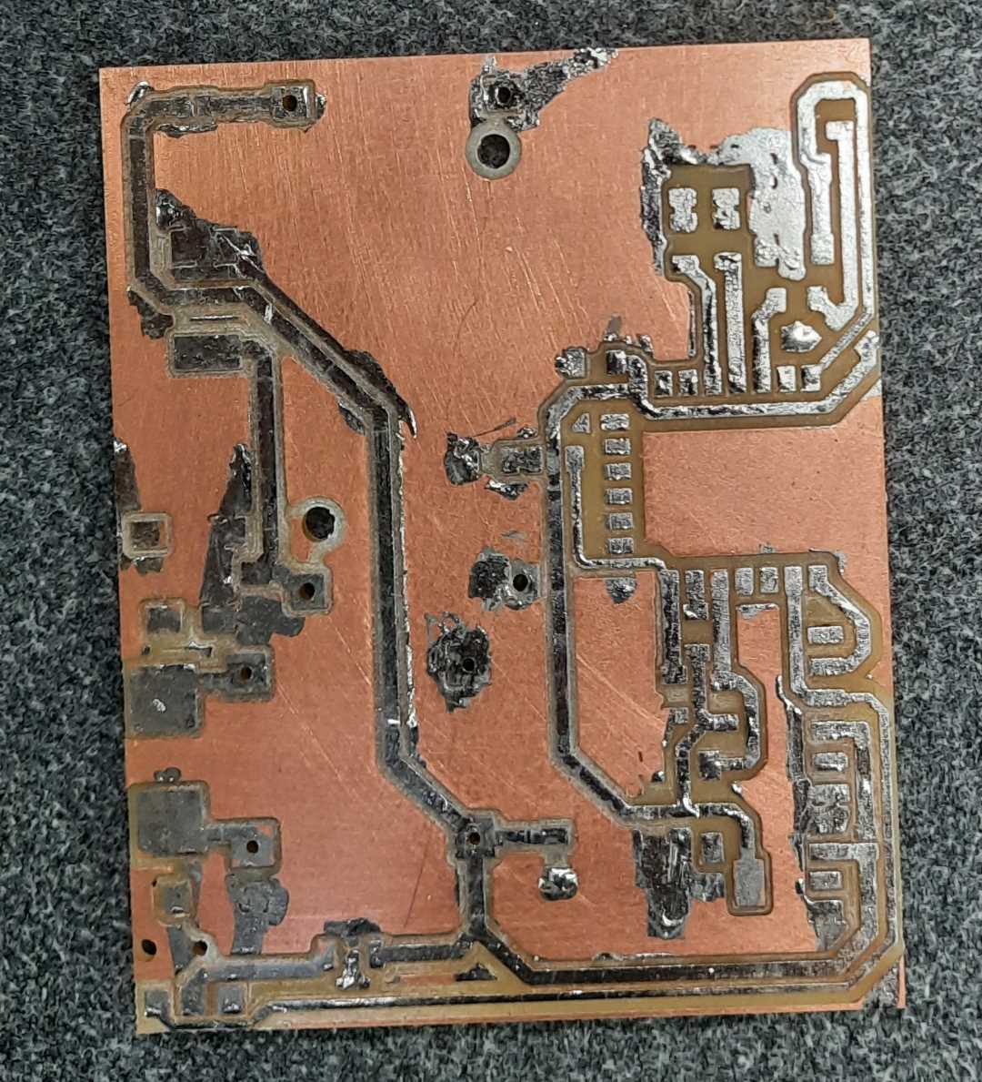
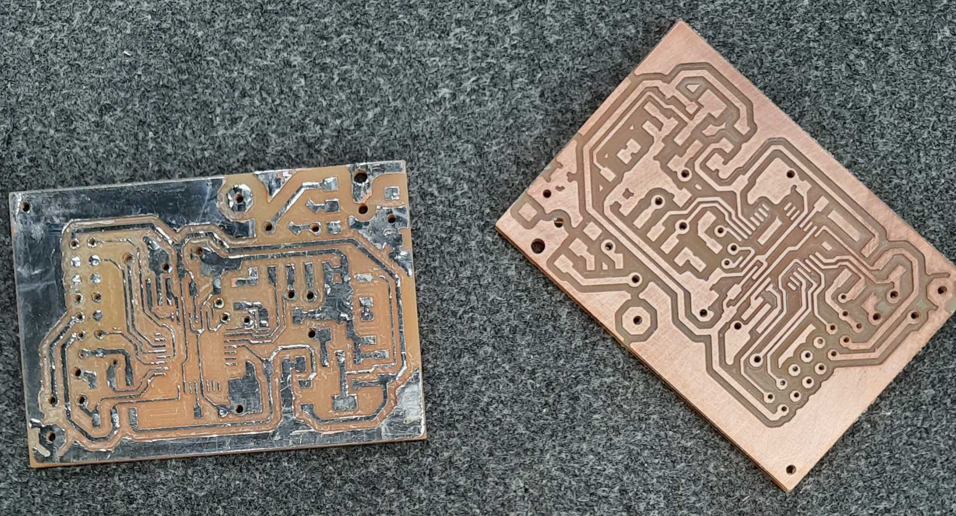
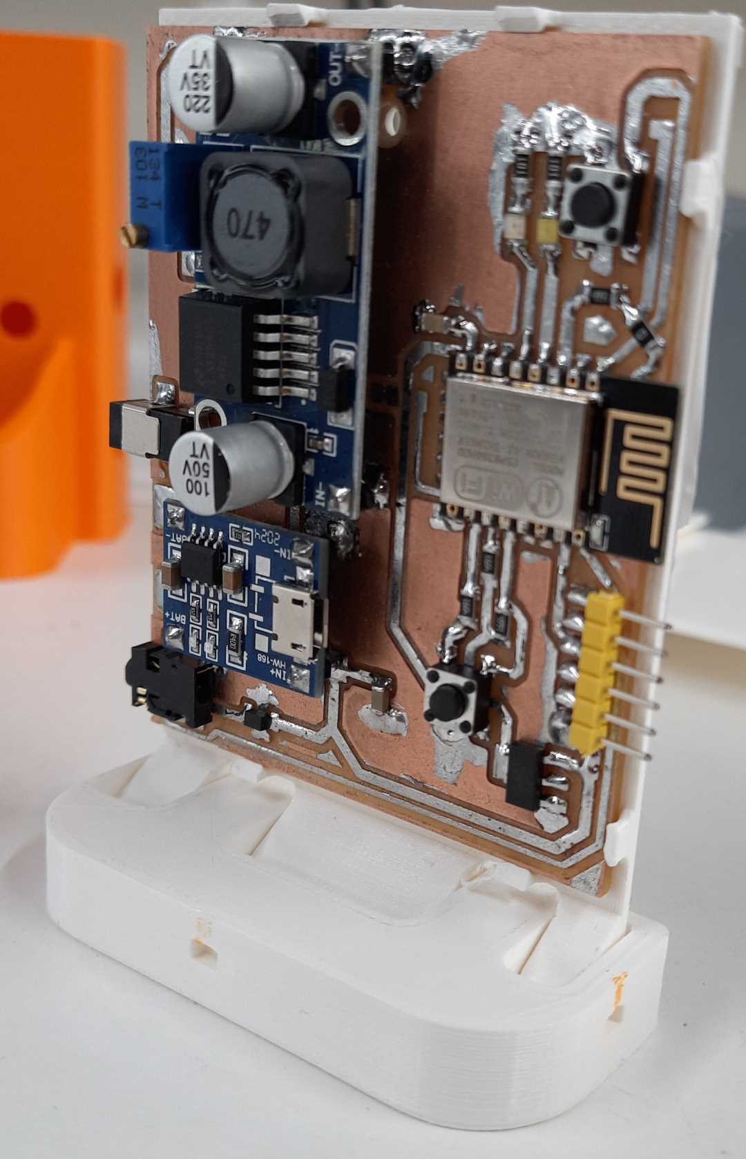
PCBs production
This section will describe the electronics production of the PCBs in the project.
Sensor
Gateway
RF transmitter and receiver
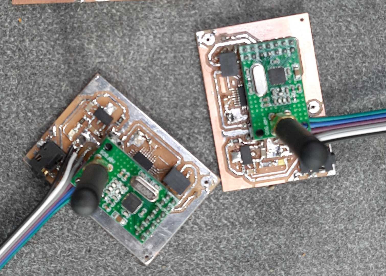
RF transmitter results video
RF recevier results video
TESTING AND PROGRAMMING
This section will describe the electronics PCBs programming and testing.
Sensor
This section will describe the sensor PCB programming and testing. I used the step response code provided to us by fab academy input week, editing it slightly; first I modified the serial communication to the Arduino SoftwareSerial, as I couldn’t get the way the code sent data to work with my other PCBs. Second I modified the data being sent to the simple readings.
click here to download the water sensor arduino code.
programming
The sensor measures the water level every minute and sends it through UART, the code is based on Neil’s step response code, as I experimented with this concept earlier in my Input devices week the programming and testing phase went smoothly without issues.
full details about the water level sensing using step response are documented in my Input devices week documentation. click here to view the water sensor Arduino code.
Gateway
programming
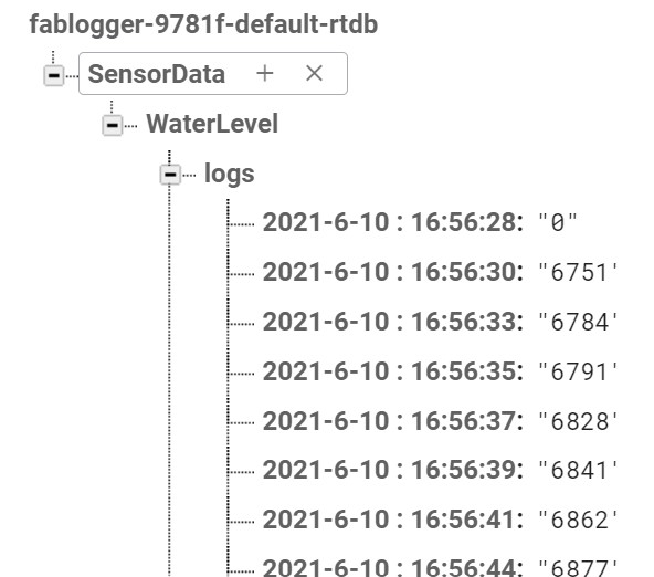
This part program takes serial data from either the sensor or the RF receiver and uploads it online to a firebase database, I used google firebase because it was faily easy to use, startups in our lab loves it because it is easy to intergate with websites and other services. I used mobizt / Firebase-ESP-Client library to send data to fireBase cloud.
I used Hieromon / AutoConnect to handle the network set up so that the wifi credntials dont have to be hard coded in the program, and if they change for any reason anyone with a phone can set it back, it makes the esp8266 act as a wifi hotspot, with a simple web interface, I can type in my wifi configurations, and it’ll be saved in the flash for future use, here is how the autoconnect web servire acts.
And after getting everything to work properly, here is a picture on fire base logging the sensor data.
click here to download the GateWay Arduino code.
RF transmitter and receiver
programming
these PCBs job is to take the sensor data through serial and send it through the NRF905 module, and recieve it on the receiver side, send it back to the gateway using serial so that the gateway would handle it the same as it would handle the data sent from the sensor itself, I used the zkemble / nRF905 library for sending the data, it faily easy to use with will documented examples.
click here to download the RF trasmitter arduino code.
click here to download the RF receiver arduino code.
HARDWARE DESIGN AND PRODUCTION
Now that all the PCBs are working well, and the project’s main functionality is done it is time to make cases for them. In this section, I will describe the device’s casing design and production.
Design Ideation
First, I will start with the sensor, I made a mold in the molding and casting week), in that week I only placed the sensor Probs inside the mold, and I found that the wires connected to it can change the reading values if something goes near them, therefore I will recast the sensor and I will place the PCB inside the mold so that there is no interference on the readings, and the UART communication should be able to send the data correctly.
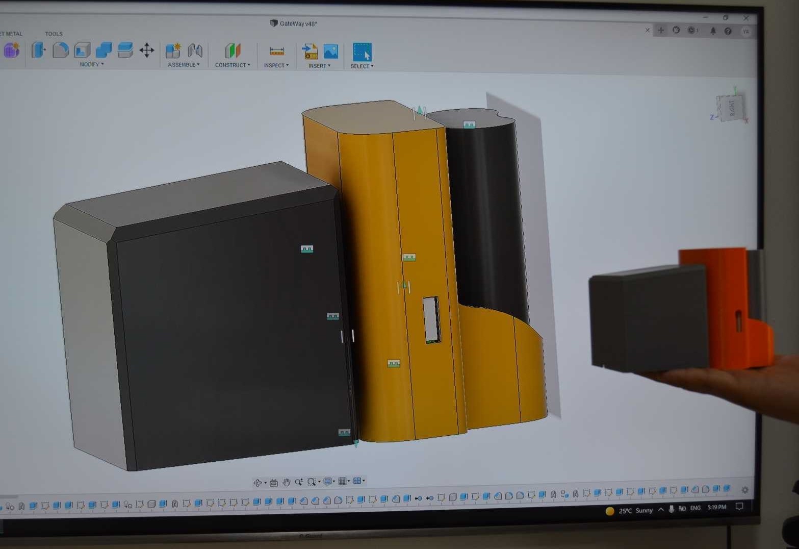
Second, the gateway, the packaging for this part is designed to be 3D printed, it houses the gateway PCB, has a slot in the back to attach the battery pack and charge it, and a slot in the front to connect the RF receiver device.
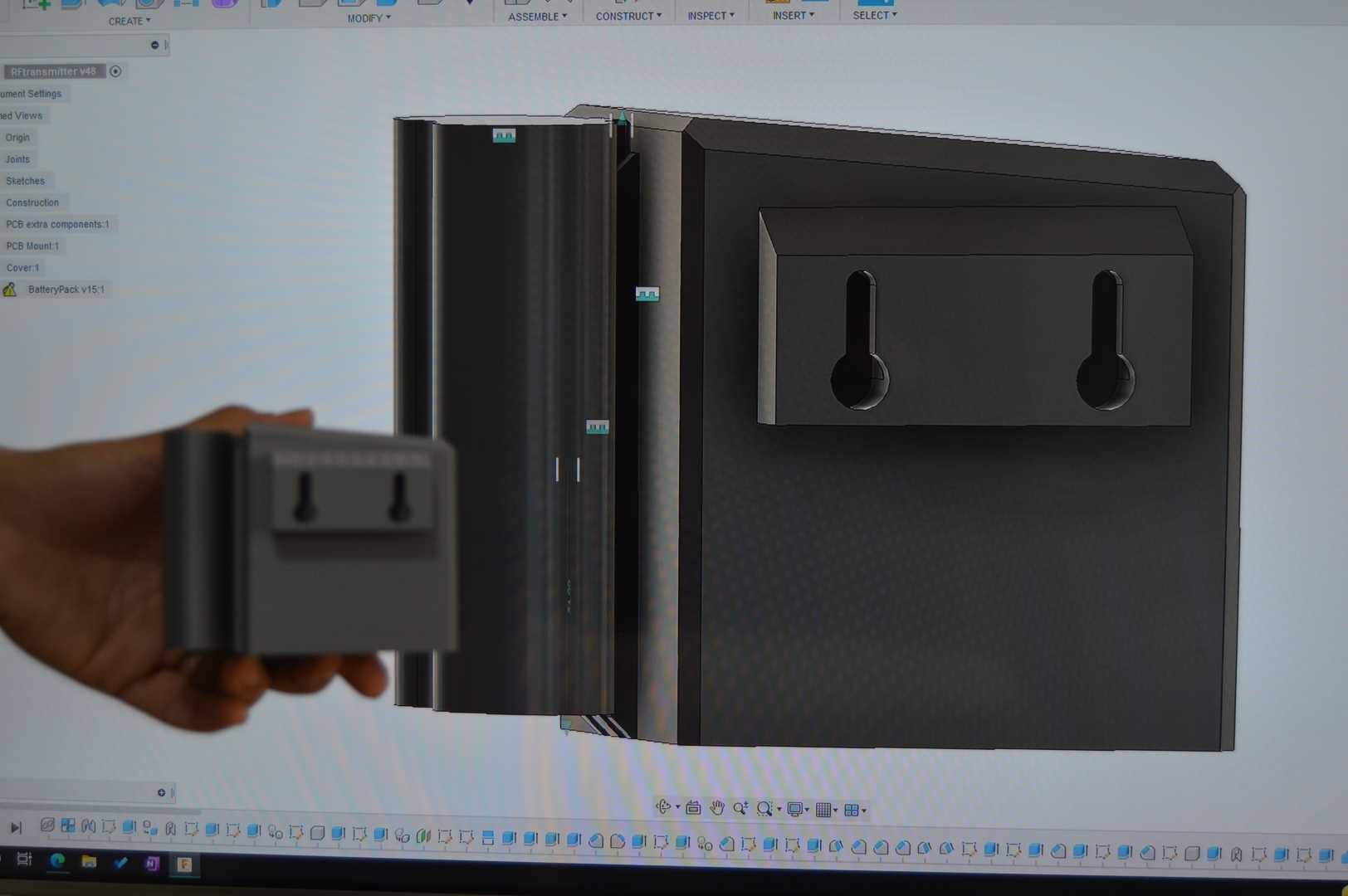
Third, the RF transmitter, the packaging for this part is designed to be 3D printed, it houses RF transmitter PCB, the design only allows access to the electronics from the bottom to achieve water protection to the PCBs, and have mounting holes on the side if it is to hang on a wall.
Finally, the RF receiver, the packaging for this part is designed to be 3D printed, it houses the RF receiver PCB, the design should have a slot that matches the one on the gateway so that it can be connected to it if it is used.
Casting production
Water level sensor
In the molding and casting week, I cased the step response probs into a mold to make it wire proof, I found that I am picking up way too much noise from the cable that connects the probes to the sensor circuit board, therefore I opt to case the circuit board inside the casted mold to minimize the disturbances, and since the PCB is sending a digital signal, it is much less likely to pick up noise.
I kept using the silicon mold that I used in the molding and casting week, I only design a simple 3D printed part that have pockets for the PCB and its probs to be placed inside the mold. The results came out great, I stopped getting noise on the signal. The only downside to this method is that I cannot change parts or connections on the PCB, or change the program inside the microcontroller. If I have to make a change, I have to make another sensor from scratch.
Here is a video of the castings process
3D printing production
Gateway
RF transmitter
RF receiver
FINAL RESULTS
Here is the project demo Video
Recommendation
design files
click here to download the electronics design files
click here to download the hardware design files