7. Electronics design
This week I worked on designing a PCB using KiCAD, I am comfortable with Autodesk eagle, so I decided to learn a new software this week.
Block diagram
I like to start planning ahead with a block diagram to make sure I don’t forget to include anything in the schematic, Here is a picture of the block diagram.

KiCad
schematic
I used the library provided to us in the fab academy website, the process was fairly simple just like the video tutorial in the lecture page.
add parts
To add parts click on the browse symbol libraries button, all the parts that I used are included in the fab library provided by fabacademy.

connect parts
to connect parts, use the wire tool to creat connections between the nodes, you can use labels to connect pins in a more orgenized manner, any 2 wires with the same label name are automaticly connected to each other.


More on the design
The input that I added is an adxl343 accelerometer, I used this design from the input week as refrance.

The output I used is an RGB, here is how its connected.

and for power I added a voltage regulator thats gets its input voltage form a jack, solder pads that I can connect wires to, the FTDI cable, and the ISP connector.

and finally the microcontroller I used is the ATtiny44, I used the ATtiny44 echboard design as refrance, which has a ISP connector for programming, FTDI for UART communication, a resonator to ganerat a clock cycle, a pull up resistor on the reset pin to maintain running operation, and a decoupling capacitor to regulate the voltage around the controller.

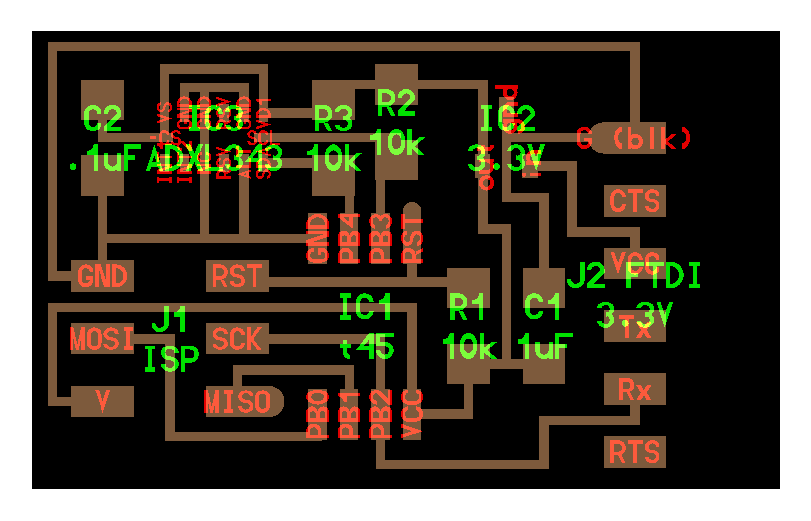
final schematic
Here is the PCB schematic, I found later that I couldn’t get the Accelerometer to work in software I2c and I had to solder some wires to alter the connections.

Board design
After finishing the schematic, I switched to the board layout. to switch to the board layout use this tool.

and after that, go to PCB setup to setup the design rules.

design rules
The best way to start routing is to define a set of rules to specify the design rules to set the manufacturing limitations, In the case of CNC milling I’m bound to the diameter of the milling bit that I will use to manufacture the PCB, which is 0.4mm, the smallest trace width that I found I can mill in the lab is 0.35mm so I set that in the design rules, and the smallest hole I can make should be bigger than the milling bit that I can use for drilling, which is 0.8mm.

routing
routing a straightforward operation just like in the tutorial video. I did place the power jack in reverse in the top left corner and that made it impossible to use, but I was able to solder power lines in the power pads.
Top layer

bottom layer

Manufacturing
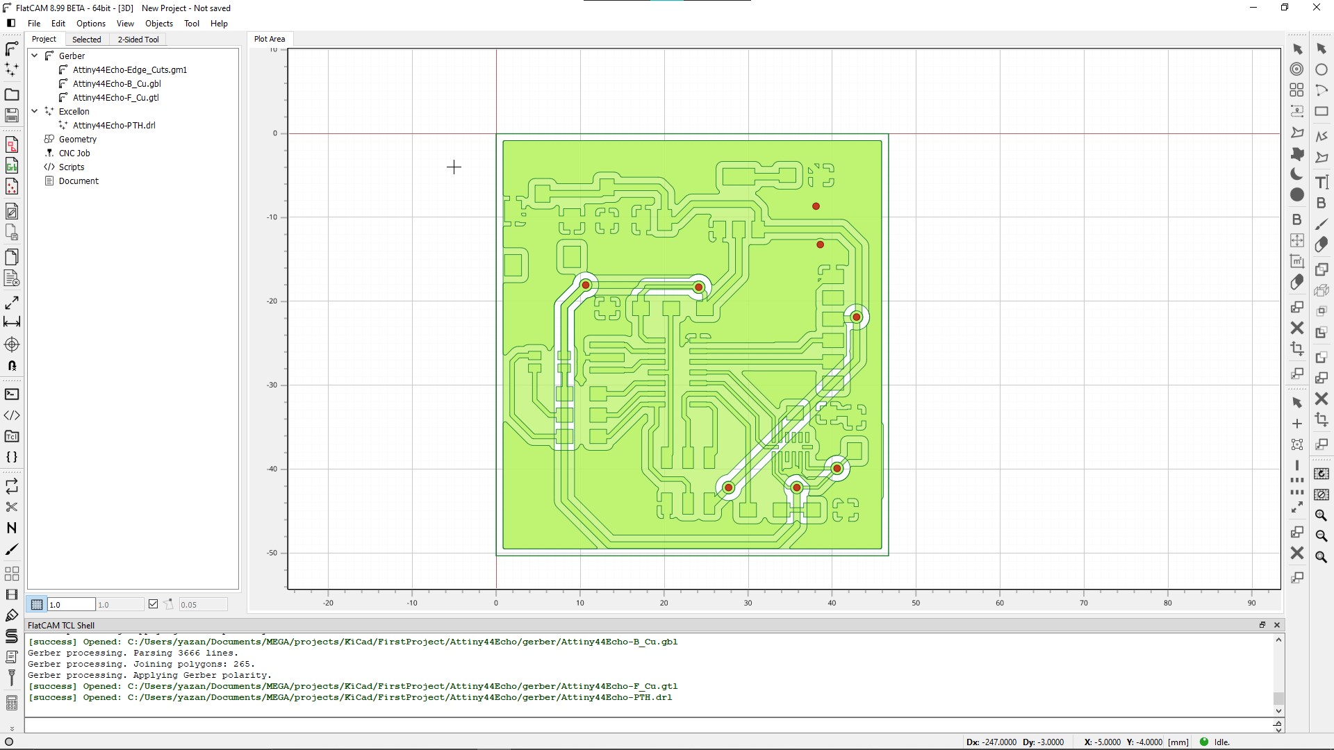
Export GERBER
The first step in manufacturing is to prepare the cam files, I exported GERBER files from KiCad and used FlatCam to generate the machine G-code.

!
Miliing traces
I started with the Top layer, setting the tool diameter to 0.4mm with 4 passes to clear more copper to make soldering easier,

after inspecting the tool path I found that 0.4mm is too big to mill the accelerometer traces.

Since I don’t have any smaller milling bits, I adjusted the size on the accelerometer pads by right-clicking on each pad, click properties and edit the pad’s size till the milling bit could go inside and separate the traces properly.


drills
I added 2 holes outside the PCB borders to guide the board to flip to its correct origin place.


Bottom layer
when preparing the bottom layer I used the 2 sided tool to horizontal flip the PCB, and when milling the PCB I have to remember to flip the PCB the same way so that the traces would align with the vias.

OutCut
finally preparing a cutting page around the board the disconnect it from the stock.

final results
After milling and soldering, production Week have more details about, the board is ready for testing, as I mentioned earlier I had issues getting the accelerometer to work, so I changed the I2C lines to the ATtiny hardware I2C pins and I had to pull then up with resistors to get it to work.

Testing
InPut test
Here I am reading the accelerometer data through serial communication.
Video
Design Files
Click here to download the design files.
Code
#include <TinyWireM.h>                  // I2C Master lib for ATTinys which use USI

#include <SoftwareSerial.h>

SoftwareSerial mySerial(0, 1); // RX, TX

#define BUFFER_SIZE 25


#define ADXL343_ADDRESS                 (0x53)    // I2C ADXL343 ALT Address
#define ADXL343_REG_DATAX0              (0x32)    // X-axis data 0
#define ADXL343_REG_DATAY0              (0x34)    // Y-axis data 0
#define ADXL343_REG_DATAZ0              (0x36)    // Z-axis data 0

char buffer[10];

uint8_t adxl343WriteRegister(uint8_t reg, uint8_t value) {
  TinyWireM.beginTransmission(ADXL343_ADDRESS);
  TinyWireM.write((uint8_t)reg);
  TinyWireM.write((uint8_t)value);
  TinyWireM.endTransmission();
}

uint8_t adxl343ReadRegister(uint8_t reg) {
  TinyWireM.beginTransmission(ADXL343_ADDRESS);
  TinyWireM.write((uint8_t)reg);
  TinyWireM.endTransmission();
  TinyWireM.requestFrom(ADXL343_ADDRESS, 1);
  return TinyWireM.read();
}

int16_t adxl343ReadWord(uint8_t reg) {
  TinyWireM.beginTransmission(ADXL343_ADDRESS);
  TinyWireM.write((uint8_t)reg);
  TinyWireM.endTransmission();
  TinyWireM.requestFrom(ADXL343_ADDRESS, 2);
  return (uint16_t)(TinyWireM.read() | (TinyWireM.read() << 8));
}


void setup() {
  delay(2000);


  mySerial.begin(9600);
  mySerial.flush();
  mySerial.print("hello_serial: starting\n");

  TinyWireM.begin();

  uint8_t deviceId = adxl343ReadRegister(0x00);
  mySerial.print(" deviceId: ");
  mySerial.println(deviceId);

  adxl343WriteRegister(0x2D,0x08); // POWER_CTL register
  adxl343WriteRegister(0x31,0x08); // Full res register

}

void loop() {
  delay(1000);

  mySerial.print("x: ");
  mySerial.print(adxl343ReadWord(ADXL343_REG_DATAX0));
  mySerial.print("    \ty: ");
  mySerial.print(adxl343ReadWord(ADXL343_REG_DATAY0));
  mySerial.print("    \tz: ");
  mySerial.println(adxl343ReadWord(ADXL343_REG_DATAZ0));
}
OutPut test
Here I am changing the RGB LED color in response to the accelerometer reading.
video
Code
#include <TinyWireM.h>                  // I2C Master lib for ATTinys which use USI

#define red   8
#define green 7
#define blue  5


#define BUFFER_SIZE 25


#define ADXL343_ADDRESS                 (0x53)    // I2C ADXL343 ALT Address
#define ADXL343_REG_DATAX0              (0x32)    // X-axis data 0
#define ADXL343_REG_DATAY0              (0x34)    // Y-axis data 0
#define ADXL343_REG_DATAZ0              (0x36)    // Z-axis data 0

char buffer[10];

uint8_t adxl343WriteRegister(uint8_t reg, uint8_t value) {
  TinyWireM.beginTransmission(ADXL343_ADDRESS);
  TinyWireM.write((uint8_t)reg);
  TinyWireM.write((uint8_t)value);
  TinyWireM.endTransmission();
}

uint8_t adxl343ReadRegister(uint8_t reg) {
  TinyWireM.beginTransmission(ADXL343_ADDRESS);
  TinyWireM.write((uint8_t)reg);
  TinyWireM.endTransmission();
  TinyWireM.requestFrom(ADXL343_ADDRESS, 1);
  return TinyWireM.read();
}

int16_t adxl343ReadWord(uint8_t reg) {
  TinyWireM.beginTransmission(ADXL343_ADDRESS);
  TinyWireM.write((uint8_t)reg);
  TinyWireM.endTransmission();
  TinyWireM.requestFrom(ADXL343_ADDRESS, 2);
  return (uint16_t)(TinyWireM.read() | (TinyWireM.read() << 8));
}


void setup() {
  delay(2000);

  pinMode(red , OUTPUT);
  pinMode(green , OUTPUT);
  pinMode(blue , OUTPUT);

  digitalWrite(red , HIGH);
  digitalWrite(green , HIGH);
  digitalWrite(blue , HIGH);

  TinyWireM.begin();

  uint8_t deviceId = adxl343ReadRegister(0x00);

  adxl343WriteRegister(0x2D,0x08); // POWER_CTL register
  adxl343WriteRegister(0x31,0x08); // Full res register

}

void loop() {

  delay(50);
  analogWrite(red , adxl343ReadWord(ADXL343_REG_DATAX0));
  analogWrite(green , adxl343ReadWord(ADXL343_REG_DATAY0));
  analogWrite(blue , adxl343ReadWord(ADXL343_REG_DATAZ0));

}