11. Input devices
This week is about sensors, I want to try a water level sensor for my final project, and I will be reffaring to the accelerometer sensor PCB I made in the electronics design week.
Research
the initial intention is to build a hydroponics system for my final project, I needed a water level sensor to measure the water level in the system water tank and alarm the owner if the water went below a specific level. As my project went I changed my final project to a generic data logging system, where the sensor sends data through UART serial communication to an RF transmitter unit, which in its turn sends the data to a gateway connected to the internet.
I kept this sensor as an example for a sensor connected to my system, but the final project can log any sensor data, for more details about my final project please visit my final project documntation page
inspiration projects:
The idea is to use a step response sensor to measure the water level of a water tank.
water level sensor PCB manufacturing
I made the 2 PCBs on the Input devices page, it’s fairly easy built, an ATtiny45 and few components, for a detailed description for PCB manufacturing please check electronics production assignment week.
PCB with two electrodes, sender and receiver.
principle of operation
The sensor simply detects the capacitance between two conductives, one of these conductives the transmitter pin, is charged with 5V using the GPIO peripheral, then discharged. after each charge and discharge, I measure the analog voltage at the receiver pin, the receiver pin is held at half the VCC voltage using a voltage divider between two 1M ohm resistors one connected to the ground and the second to VCC as shown in the schematic below.
Water level sensor PCB
After testing, I made my design replacing the FTDI connector with the 2.5mm jack to receive power and trasmmit data as all my final project part uses this connector
schematic
click to download schematic file
board
click to download schematic file
manufacturing pictures

Programming and testing
I usually start by burning an Arduino bootloader to any PCB I make to make sure the soldering is ok, in this board caused me some issues that I will get into later on.
Code
//
// hello.txrx.45.c
//
// step response transmit-receive hello-world
//    9600 baud FTDI interface
//
// Neil Gershenfeld
// 11/6/11
//
// (c) Massachusetts Institute of Technology 2011
// This work may be reproduced, modified, distributed,
// performed, and displayed for any purpose. Copyright is
// retained and must be preserved. The work is provided
// as is; no warranty is provided, and users accept all
// liability.
//

#include <avr/io.h>
#include <util/delay.h>

#define output(directions,pin) (directions |= pin) // set port direction for output
#define set(port,pin) (port |= pin) // set port pin
#define clear(port,pin) (port &= (~pin)) // clear port pin
#define pin_test(pins,pin) (pins & pin) // test for port pin
#define bit_test(byte,bit) (byte & (1 << bit)) // test for bit set
#define bit_delay_time 102 // bit delay for 9600 with overhead
#define bit_delay() _delay_us(bit_delay_time) // RS232 bit delay
#define half_bit_delay() _delay_us(bit_delay_time/2) // RS232 half bit delay
#define settle_delay() _delay_us(100) // settle delay
#define char_delay() _delay_ms(10) // char delay
#define nloop 100 // loops to accumulate

#define serial_port PORTB
#define serial_direction DDRB
#define serial_pin_out (1 << PB2)
#define transmit_port PORTB
#define transmit_direction DDRB
#define transmit_pin (1 << PB4)

void put_char(volatile unsigned char *port, unsigned char pin, char txchar) {
   //
   // send character in txchar on port pin
   //    assumes line driver (inverts bits)
   //
   // start bit
   //
   clear(*port,pin);
   bit_delay();
   //
   // unrolled loop to write data bits
   //
   if bit_test(txchar,0)
      set(*port,pin);
   else
      clear(*port,pin);
   bit_delay();
   if bit_test(txchar,1)
      set(*port,pin);
   else
      clear(*port,pin);
   bit_delay();
   if bit_test(txchar,2)
      set(*port,pin);
   else
      clear(*port,pin);
   bit_delay();
   if bit_test(txchar,3)
      set(*port,pin);
   else
      clear(*port,pin);
   bit_delay();
   if bit_test(txchar,4)
      set(*port,pin);
   else
      clear(*port,pin);
   bit_delay();
   if bit_test(txchar,5)
      set(*port,pin);
   else
      clear(*port,pin);
   bit_delay();
   if bit_test(txchar,6)
      set(*port,pin);
   else
      clear(*port,pin);
   bit_delay();
   if bit_test(txchar,7)
      set(*port,pin);
   else
      clear(*port,pin);
   bit_delay();
   //
   // stop bit
   //
   set(*port,pin);
   bit_delay();
   //
   // char delay
   //
   bit_delay();
   }

int main(void) {
   //
   // main
   //
   static unsigned char count;
   static uint16_t up,down;
   //
   // set clock divider to /1
   //
   CLKPR = (1 << CLKPCE);
   CLKPR = (0 << CLKPS3) | (0 << CLKPS2) | (0 << CLKPS1) | (0 << CLKPS0);
   //
   // initialize output pins
   //
   set(serial_port, serial_pin_out);
   output(serial_direction, serial_pin_out);
   clear(transmit_port, transmit_pin);
   output(transmit_direction, transmit_pin);
   //
   // init A/D
   //
   ADMUX = (0 << REFS2) | (0 << REFS1) | (0 << REFS0) // Vcc ref
      | (0 << ADLAR) // right adjust
      | (0 << MUX3) | (0 << MUX2) | (1 << MUX1) | (1 << MUX0); // PB3
   ADCSRA = (1 << ADEN) // enable
      | (1 << ADPS2) | (1 << ADPS1) | (1 << ADPS0); // prescaler /128
   //
   // main loop
   //
   while (1) {
      //
      // accumulate
      //
      up = 0;
      down = 0;
      for (count = 0; count < nloop; ++count) {
         //
         // settle, charge
         //
         settle_delay();
         set(transmit_port, transmit_pin);
         //
         // initiate conversion
         //
         ADCSRA |= (1 << ADSC);
         //
         // wait for completion
         //
         while (ADCSRA & (1 << ADSC))
            ;
         //
         // save result
         //
         up += ADC;
         //
         // settle, discharge
         //
         settle_delay();
         clear(transmit_port, transmit_pin);
         //
         // initiate conversion
         //
         ADCSRA |= (1 << ADSC);
         //
         // wait for completion
         //
         while (ADCSRA & (1 << ADSC))
            ;
         //
         // save result
         //
         down += ADC;
         }
      //
      // send framing
      //
      put_char(&serial_port, serial_pin_out, 1);
      char_delay();
      put_char(&serial_port, serial_pin_out, 2);
      char_delay();
      put_char(&serial_port, serial_pin_out, 3);
      char_delay();
      put_char(&serial_port, serial_pin_out, 4);
      //
      // send result
      //
      put_char(&serial_port, serial_pin_out, (up & 255));
      char_delay();
      put_char(&serial_port, serial_pin_out, ((up >> 8) & 255));
      char_delay();
      put_char(&serial_port, serial_pin_out, (down & 255));
      char_delay();
      put_char(&serial_port, serial_pin_out, ((down >> 8) & 255));
      char_delay();
      }
   }
Upload
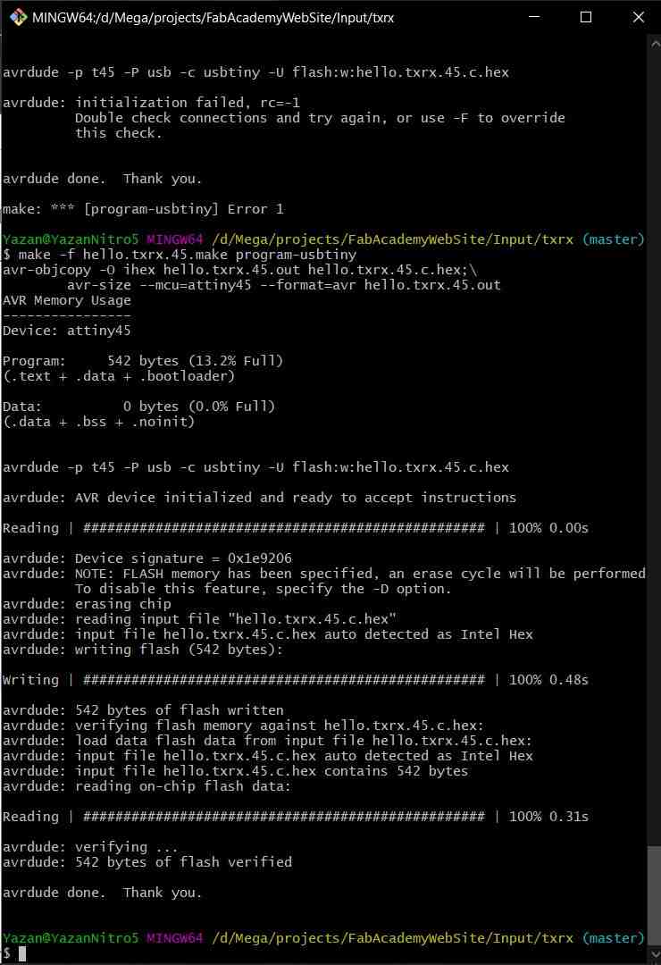
I uploaded the code in the Input page website to the PCB using the following command while in the file directory, using bash in win10.
make -f hello.txrx.45.make program-usbtiny
and got the following results.
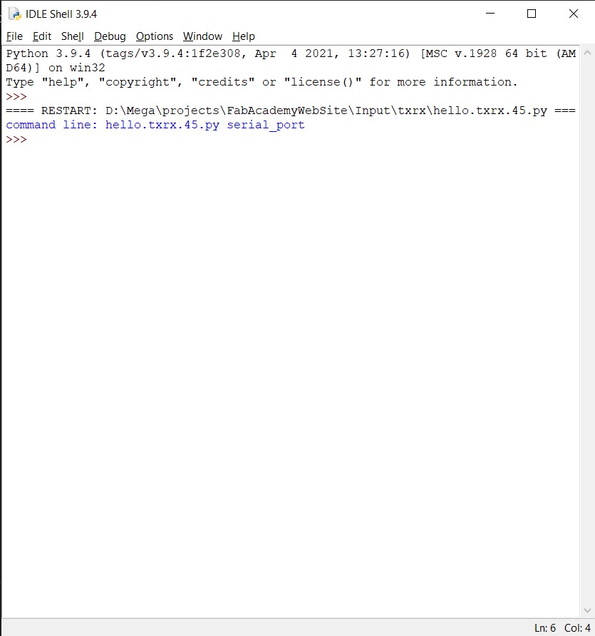
then I moved to get the python code running to test, and it was much more tricky than I had expected, at first I downloaded Python from their official website, once I tried to run the code a window would pop up then closes by itself.
to try and see what is happening I opened the code in the python shell software and got these results once I run the code.
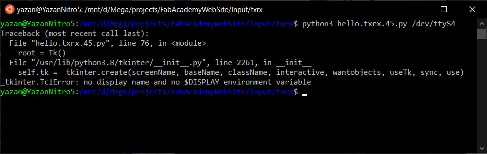
after some search I figured that has to pass a second argument to the script which has the serial port number, therefor I went and tried to run the script using the Linux subsystem for win10. after installing python, pip, and the needed libraries, the scrip says that ‘no display name and no $DISPLAY environment variable.
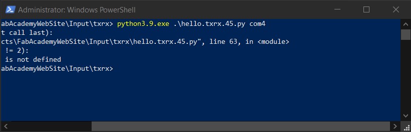
from there I moved to win10 PowerShell which I’m not familiar with, but it was fairly simple to use and I was able to get the python environment ready to run the script.
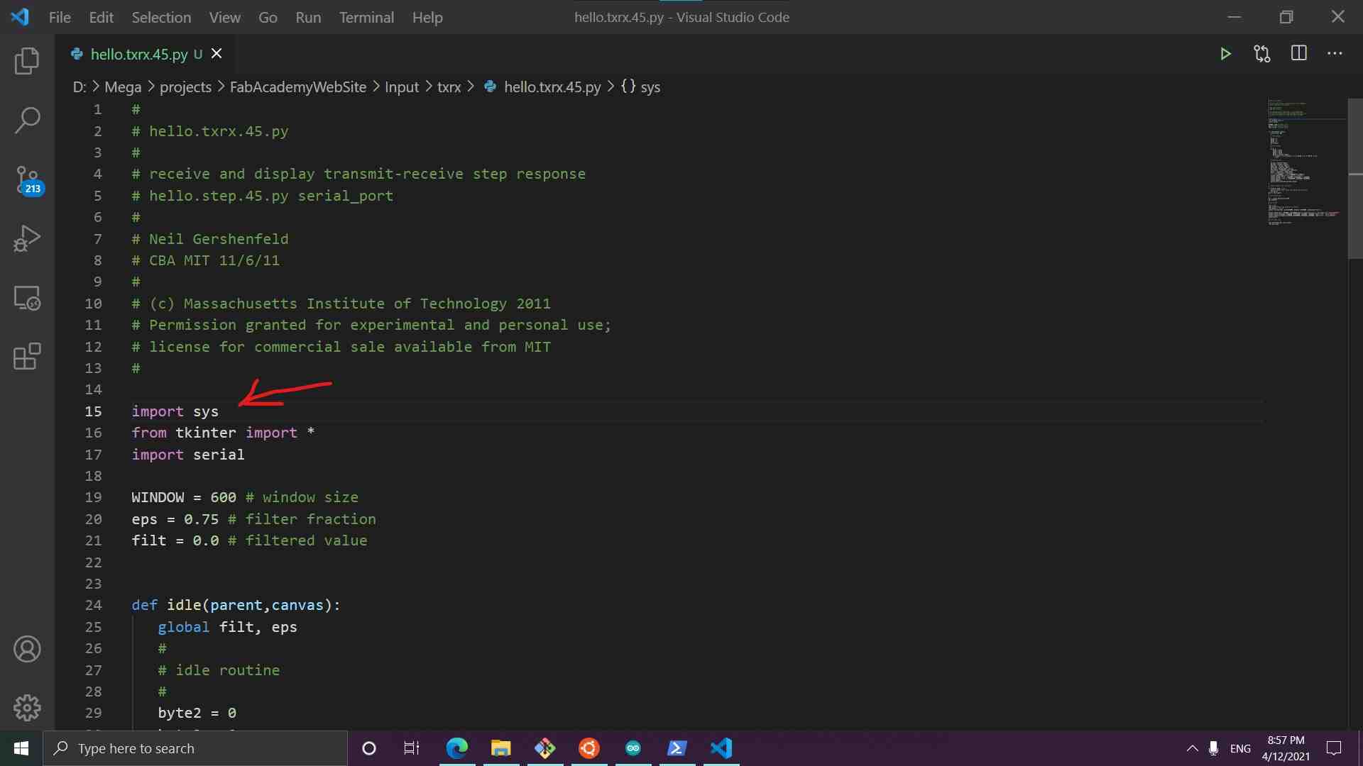
once I tried to run the script I got this error, ‘NameError: name ‘sys’ is not defined’.
and after some search I got the script to run after adding this line to the code.
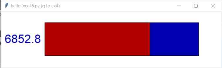
Now finally the python script is running, but it was stuck to 1.

I had no idea why it was frozen like that, so I started a trip of troubleshooting, I made sure the right code is uploaded to the microcontroller if the PCB is well soldered, did I reference the serial port correctly and nothing worked.
I even made a bootable Linux flash and redid the whole thing and still no result, the microcontroller flashing and dealing with the python code was much simpler on Linux though.
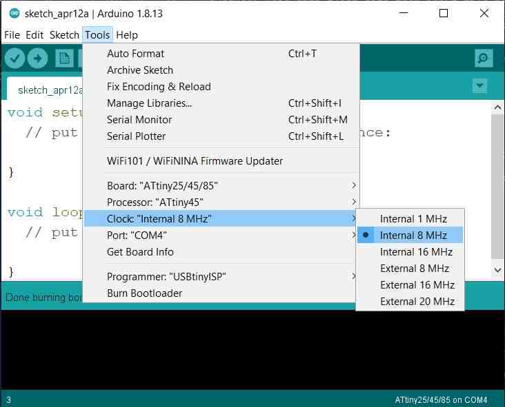
so I opened the C code to try and find anything, and in the makefile, I found that the code should use an 8MHZ clock, and there I remembered that I did an Arduino burn bootloader to my PCB with a different speed after I finished soldering.
So I redid that step making sure I burn the bootloader with an 8MHz clock time.
and It finally works perfectly after hours of looking.
here is a video testing the copper sheets in water and seeing how the readings vary.
here is a video testing the copper sheets facing each other mounted on simple acrylic sheets
here is a video testing the copper sheets in a fork shape on one acrylic sheet
oscilloscope
here is a video seeing the transmitter and receiver line on the oscilloscope.
accelerometer sensor
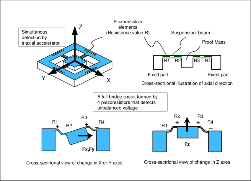
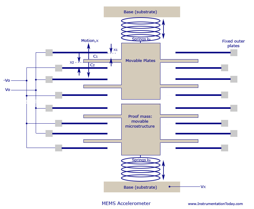
In this project I used the ADXL343 3-axis accelerometer to measure the tilt angle of a PCB, a 3-axis accelerometer measures the deflection of a block of mass. using the deflection, the sensor can detect the mass acceleration, forces, and tilt angle as the earth’s gravitational force is known.
the ADXL343 sends the deflection readings digitally through a serial communication protocol. In the project I used, I am receiving the data through the I2C communication protocol using a library from Adafruit.
please check the project PCB design, manufacturing, programming, and testing in the electronics design week, where I designed and programmed an accelerometer sensor board with a RGB output.